Note: Descriptions are shown in the official language in which they were submitted.
BC9-91-012
2059928
MULTIMEDIA EXPANSION UNIT
Background of the Invention
The present invention relates to multimedia computer
systems. Multimedia computer systems are information
handling systems which combine the information handling
characteristics of traditional computer systems with high
quality video and audio presentations. The video
presentation is provided by a video display device, and the
audio presentation is provided by an audio output device.
Multimedia computer systems include media sources which
generate media signals. The media signals include audio
signals, which are provided to the audio output device, and
image signals, which are provided to the video display
device. The image signals may include graphics signals,
text signals, animation signals and full motion video
signals. An image signal is converted to a video
presentation by the display device, which receives the image
signal and scans the image signal in a raster pattern across
a screen of the display device. The speed with which the
display device scans the image is called the sweep rate.
The screen has a horizontal resolution and a vertical
resolution which define display device screen coordinates.
The presentation from one complete scan of the screen is
called a frame. To provide a full motion video
presentation, a display device generates multiple frames per
second.
Summary of the Invention
It has been discovered that by providing an expansion
unit which incorporates a multimedia architecture, the
expansion unit being connected to an existing computer
system via an expansion slot of an I/O bus of the existing
computer as well as via a display device output terminal of
the computer, a multimedia solution is presented which
allows a multimedia architecture to be implemented on an
existing computer system.
Brief Description of the Drawings
BC9-91-012 2 2 0 5 9 9 2 8
Fig. 1 is a block diagram of a multimedia system
according to the present invention.
Fig. 2 is an example of a composed frame.
Fig. 3 is a block diagram of a media control module and
an audio module of the Fig. 1 multimedia system.
Figs. 4A and 4B are front and rear views, respectively,
of a multimedia system according to the present invention.
Fig. 5 is an exploded view of the multimedia expansion
unit of the Fig. 1 multimedia system.
Detailed Description
Referring to Figs. 1, 4A and 4B, multimedia system 10
includes: computer 11, which may be for example, an IBM~
Personal System/2~ personal computer; multimedia expansion
unit 12; display device 14, which may be for example an all
points addressable (APA) video graphics array (VGA) or high
definition television (HDTV) display device; audio output
device 15, which may be for example speakers or headphones;
input device 16, which may be for example a keyboard or a
mouse; and, analog full motion video source 17, which may be
for example, a video tape player or a video disk player.
Multimedia expansion unit 12 is arranged in modules;
information is transferred among modules via media bus 24.
Information is provided to and received from multimedia
expansion unit 12 via system interface 20 and display
interface 21. System interface 20 is inserted into an
expansion slot of an I/0 bus of computer 11. Display
interface 21 is connected to a display device output
terminal of computer 11, i.e., to the connector of computer
11 to which a display device is normally connected.
Multimedia expansion unit 12 includes media control
module 30 and may include audio module 31, graphics
accelerator module 34, and programmable receiver module 38.
Modules 34, and 38, which are media sources (i.e., devices
which provide media signals), are each connected to media
bus 24 via media bus interface circuits 39a, 39b
respectively. (Media bus interface circuits 39a, 39b are
referred to generally as bus interface circuit 39.) Image
signals from the media sources selectively access media bus
24 in response to control information; the selective access
BC9-91-012 3 2059928
. ~
allows real time composition of the image signals. Audio
signals from the media sources selectively access media bus
24 in response to control information; the selective access
allows real time composition of the audio signals.
A composed image signal is provided from media bus 24
to display device 14 via media control module 30; a composed
audio signal is provided to audio output device 15 via audio
module 31. Programmable receiver 38 receives analog full
motion video input information directly from video source
17; programmable receiver 38 may also receive
electromagnetic transmissions from remote transmitters
(e.g., television transmissions from television studios).
The configuration of multimedia system 10 and of multimedia
expansion unit 12 is meant to be representative; it is
understood that the system and core configurations may be
changed to satisfy a user s needs.
Media bus 24 conforms to the media bus architecture
which is described herein. Media bus 24 is connected
between media control module 30, audio module 31 and media
bus interface circuits 39 of media sources such as graphics
accelerator module 34 and programmable receiver module 38.
Media expansion unit 12 composes image signals in real
time for display by display device 14. In other words,
media core 12 combines image signals in parallel in real
time on a point by point basis for display by display device
14. For the purposes of this application, "real time" is
determined with reference to the sweep rate of display
device 14, i.e., the speed with which information is
presented by display device 14. Accordingly, the speed with
which media bus 24 transmits information need only be as
fast as the sweep rate of display device 14.
An image signal which is provided by a media source is
provided to media bus 24 via a respective media bus
interface circuit 39 on a point by point basis in response
to control information; an image signal which is provided by
computer 11 is provided via display interface 21 on a point
by point basis in response to control information. A point
is related to the resolution of display device 14.
Accordingly, if display device 14 is a 640 by 480 VGA
monitor, a point corresponds to a coordinate of the VGA
monitor. Alternately, if display device 14 is a 1920 by
BC9-91-012 4 2059928
1035 HDTV monitor, a point corresponds to a coordinate of
the HDTV monitor.
A virtual screen implementation (i.e., every module, as
well as computer system 11, assumes that it is providing an
image signal to a display) is used by multimedia system 10
to achieve application transparency. A virtual screen
implementation creates the appearance to each module of a
dedicated display device. Thus, each media source which is
generating an image signal generates that image signal
whether or not the media source is granted access to media
bus 24.
An image signal which is contained on media bus 24 is
received by media control module 30 on a point by point
basis and is provided to display device 14 on a point by
point basis. The combination of the image signals from the
media sources on media bus 24 provides a preliminary
composed image signal which is provided to media control
module 30. Media control module 30 combines this
preliminary composed image signal with any image signal
which is provided by computer 11 to provided a composed
image signal to display device 14. Media control module 30
adjusts the attributes (e.g., the voltage level) of the
composed image signal to correspond to the attributes
required by display device 14 and drives an ad3usted
composed image signal to display device 14.
Referring to Fig. 2, an example of a composed frame is
shown. For the purposes of this example, display device 14
is a VGA display device having a display resolution of 640
columns by 480 rows. The image signal which provides the
background plane is provided by computer 11. An image
signal which is displayed in a first window (WINDOW 1) is
provided by programmable receiver 38; this image signal is a
full motion video signal. An image signal which is
displayed in a second window (WINDOW 2) is provided by
graphics accelerator module 34. It is understood that the
example shown is merely meant to be illustrative of the
invention.
The example shown is for one frame of display device
14. This frame is repeated multiple times per second thus
allowing display device 14 to provide a full motion
presentation. Accordingly, the following description of a
BC9-91-012 5
2059928
composition of a frame is repeated multiple times per
second.
During composition of the frame, bus interface circuits
39 allow selective access to media bus 24 of respective
media sources in response to control information. In the
preferred embodiment, the control information is provided by
media control module 30. The control information which is
provided to bus interface circuits 39 includes switching
coordinate information as well as window priority
information. This control information is provided when the
frame is initially composed and is maintained within bus
interface circuits 39 until the information for a particular
module changes, ie., multiple frames may be composed from
the same switching coordinate information. If certain
switching coordinate information is modified (e.g., because
the display area of a particular module changes) then the
modified switching coordinate information is provided to the
appropriate bus interface circuit 39. This modified
switching coordinate information is substituted within the
appropriate bus interface circuit 39.
Synchronized media sources drive media bus 24 in real
time. Image signals are received by media control module 30
in real time. Thus for sources which are synchronized,
there is no need to store information within video memory
before displaying the information via display device 14.
Accordingly, the image signals that are contained on media
bus 24 provide a preliminary composed image which is a
single plane. Unsynchronized media sources provide image
signals to media control module 30, which synchronizes these
signals prior to display.
Composition of the frame shown in Fig. 2 is initiated
by media control module 30 providing the computer image
signal to display device 14 based upon the window priority
and switching coordinate information for computer 11.
Computer 11 provides an image signal to media control module
30. Media control module 30 provides this image signal to
display device 14 until display device 14 reaches coordinate
Hl,Vl. At this location, media control module 30 rescinds
the access grant of computer 11 and simultaneously, bus
interface circuit 39b grants programmable receiver module 38
access to media bus 24. Media control module 30 receives
BC9-91-012 6 2059928
the image signal from media bus 24 and provides this signal
to display device 14.
Programmable receiver module 38 provides an image
signal to media bus 24 until display device 14 reaches
coordinate H2,V1, at which location bus interface circuit
39b rescinds the access grant to media bus 24 of
programmable receiver module 38 and media control module 30
grants computer 11 access to display device 14. Access to
display device 14 continues to be interchanged between
computer 11 and programmable receiver module 38 at the
horizontal coordinates H1 and H2 until display device 14
reaches coordinate H2,V2.
At coordinate H2,V2, bus interface circuit 39b rescinds
the grant of access to media bus 24 of programmable receiver
module 38 and bus interface circuit 39a grants graphics
accelerator module 34 access to media bus 24. Graphics
accelerator module 34 provides an image signal to media bus
24 until location H3,V3, at which location access to display
device 14 is switched to computer 11. Access to display
device 14 continues to be exchanged between computer 11,
programmable receiver module 38, and graphics accelerator
module 34 at the horizontal coordinates H1, H2 and H3 until
display device 14 reaches coordinate H4,V3.
At coordinate H4,V3, programmable receiver 38 has
completed its contribution to the composition of the screen
to display device 14. Accordingly, for the remainder to the
screen, programmable receiver 38 is no longer granted access
to media bus 24.
At horizontal coordinates H3 and H4, access to display
device 14 is switched between computer 11 and graphics
accelerator module 34 until display device 14 reaches
coordinate H3,V4. At coordinate H3,V4, access to display
device 14 is returned to computer 11 for the remainder of
the frame.
Referring again to Fig. 1, media bus 24 serves as the
pathway for media signals defined by the media bus
architecture. The media bus architecture defines media
signals for transfer of information between media sources
and media control module 30. The media signals include
image signals, control signals and audio signals.
Accordingly, media bus 24 includes a plurality of video
BC9-91-012 7 2059928
channels, a media control channel (MCC) and an audio
channel. The video channels include a primary video channel
(PVC), a secondary video channel (SVC), and a digital video
channel (DVC).
The primary video channel is the channel via which
image signals from the media sources are composed to provide
a primary composed image signal to media control module 30.
The primary channel includes paths for a primary analog
image signal having red green and blue components ~PVC RGB),
a primary color key match (PVC CKM) signal, and a primary
arbitration signal (PVC ARB). The PVC RGB signal is a
differential analog RGB signal which is driven directly onto
the primary channel by the media sources as an analog
waveform under control of media control module 30. The PVC
CKM signal controls video switch multiplexing in media
control module 30; the PCKM signal is driven active low at
pixel rates coincident with RGB data. The PVC ARB signal is
a 4-bit one of sixteen priority arbitration signal.
The secondary video channel is the channel via which
alternate or additional image signals from the media sources
are composed to provide a secondary composed image signal to
media control module 30. The secondary channel includes
paths for a secondary analog image signal having red, green
and blue components (SVC RGB), a secondary color key match
(SVC CKM) signal, and a secondary arbitration signal (SVC
ARB). The SVC RGB signal is a differential analog RGB
signal which is driven directly onto the secondary channel
by the media sources as an analog waveform under control of
media control module 30. The SVC CKM signal controls video
switch multiplexing in media control module 30; the SVC CKM
signal is driven active low at pixel rates coincident with
RGB data. The SVC ARB signal is a 4- bit one of sixteen
priority arbitration signal.
The digital video channel is the channel via which
digital video signals are transferred from a media source to
media control module 30. The digital video channel is
capable of supporting high-speed live video transfers as
required by HDTV and other high resolution displays as well
as transfers from other digital video sources. The digital
video channel includes paths for a 32-bit image signal (DIG
IM), a digital clock signal, a digital HSync signal and a
BC9-91-012 2059928
digital VSync signal. The DIG IM signal includes an active
high 8, 16, or 24-bit RGB signal, plus an 8-bit Alpha
signal, which represents a degree of transparency. The
digital clock signal is provided by media control module 30
to clock data either through media control module 30 to the
media control module RGB output terminals or into a frame
buffer of media control module 30. The maximum clock
frequency of the digital video channel is 80 MHz, thus
supporting HDTV data rates of 74.25 MHz.
The media control channel provides paths for media
control information which controls the transfer of
information over media bus 24. The media control channel
allows media control module 30 to issue device-specific
control information as well as to broadcast global control
information to all media sources. The media control
information includes window control block data which are
written to each adapter as well as vital product data and
personality data which are read from each adapter when
system 10 is initialized. The media control channel also
includes paths for a source synchronization signal (SOURCE
SYNC) and a system synchronization signal (SYS SYNC) as well
as a master clock signal (MASTER CLK). The media control
channel also includes a path for a global reference signal
(V BIAS) which is provided to all media sources which are
connected to media bus 24.
The audio channel includes paths for a high fidelity
digital audio signal (AUDIO) as well as a telephony grade
digital (TEL AUDIO).
Referring to Figs. 1 and 3, media control module 30
provides a plurality of functions for media core 12. Media
control module 30 controls composition on media bus 24 .
Media control module 30 also functions as a receiver and
level converter for an image signal which is received from
the primary video channel, the secondary video channel or
the digital video channel. Media control module 30 also
functions as a composition facility for image signals which
are provided by computer 11. Media control module 30 also
functions as a video mixer for mixing image signals from the
primary video channel, the secondary video channel and the
digital video channel as well as image signals which are
generated internally by media control module 30. Media
BC9-91-012 9 2059928
control module 30 also functions as an image capture
facility for storing images from a media source. Media
control circuit 30 also functions as a display device driver
circuit as well as a computer display interface. Media
control module 30 also functions as a synchronization signal
generator for generating the synchronization signals for
media core 12. Media control module 30 also functions as a
composition facility for audio signals. Media control
module 30 also interfaces with the system bus of computer
11. Some of the functions which media control module 30
performs occur continuously, other functions occur as
needed. However, a plurality of functions can occur
simultaneously.
Media control module 30 receives continuous data
streams across the video channels of media bus 24 while
controlling the media sources via the media control channel.
Media control module 30 includes media control circuit 50,
bus interface circuit 51, image signal processor circuit 52,
and frame capture circuit 54, all of which are connected via
media control module bus 55. Media control module 30 also
includes display device adapter circuit 56, synchronization
generator circuit 58.
When controlling composition of image signals on media
bus 24, media control module 30 uses media control circuit
50. Media control circuit 50 includes media control module
microprocessor 62, memory controller 64, media system memory
66, which is dynamic random access memory (DRAM), and menu
memory 68, which is an electronically erasable programmable
read only memory. Media system memory 66 holds a media
control module operating system which controls the functions
of media control module 30; memory 66 also contains I/0
handling information for interfacing with input device 16.
Menu memory 68 stores menu information which may be accessed
via input device 16 (e.g., pull-down menus which are
accessed via a pointing device such as a mouse). Media
control module microprocessor 62 accesses media system
memory 66 and menu memory 68 via memory controller 64.
Memory controller 64 also controls access to any memory
which may be resident on a particular bus interface circuit
39. E.g., if a new module is added to media core 12, media
control module 30 requires media source personality data
BC9-91-012 10
20S9928
which are stored in the bus interface circuit 39 of the new
module. The media source personality data are passed in a
personality block via the media control channel 30 under
control of memory controller 64. The personality data are
used by media control module microprocessor 62.
Composition of a frame is initiated by a user defining
composition characteristics via input device 16. The
composition characteristics may include the desired size and
shape of a window via which the image signal for a
particular media source is to be displayed. Media control
module microprocessor 62, in conjunction with the I/0
handling information which is stored in media system memory
66, receives the user defined composition characteristics.
Media control module microprocessor 62 then generates
control information such as switching coordinate information
and window priority information which is transmitted via the
media control channel of media bus 24 to the media sources
which are connected to media bus 24. The media sources are
granted selective access to media bus 24 based upon this
control information.
When functioning as a receiver and level converter or
when functioning as a video mixer, media control module 30
uses image signal processor circuit 52. Image signal
processor circuit 52 includes display controller 70 as well
as mixer circuit 72. Display controller 70 functions as an
interface circuit between frame capture circuit 54 and mixer
circuit 72 because, by using frame capture circuit 54, media
control module 30 may function as a source of an image
signal. In addition to functioning as an interface between
frame capture circuit 54 and mixer 72, display controller 70
also manages acquisition and display of images which are
stored in frame capture circuit 52. Display controller 70
also manages other display functions such as background
color flood in which the background presentation of display
device 14 is set to a certain color. Display controller 70
also controls the fade level of selected frame buffer images
(e.g., the menu image or a captured image) under control of
media control module microprocessor 62.
When functioning only as a receiver and level
converter, mixer circuit 72 of image signal processor
circuit 52 receives either the PVC RGB signal, the SVC RGB
BC9-91-012 11
2059928
signal or the DIG IM signal from media bus 24. Mixer
circuit 72 levels the received image signal to provide a
composed image signal (COMP RGB) which has a constant base
output level, e.g., a constant black level.
When functioning as a leveling circuit and a mixer
circuit, mixer circuit 72 of image signal processor circuit
52 receives one or more of the PVC RGB and PVC CKM signals,
the SVC RGB and SVC CKM signals, and the DIG IM signal from
media bus 24, as well as a capture signal (MCM RGB) from
frame capture circuit 54 and the computer image signal from
computer 11. Mixer circuit 72 mixes these signals under
control of display controller 70 and levels the mixed signal
to provide the COMP RGB signal.
When functioning as a composition facility, media
control module 30 uses image signal processor circuit 52 in
conjunction with media control circuit 50. During
composition within media control module 30, mixer circuit 72
switches on a point by point basis between the PVC RGB, SVC
RGB and DIG IM signals as well as a frame capture signal
which is provided by frame capture circuit 54 and the
computer image signal which is provided by computer 11 to
provide the COMP RGB signal. Display controller 70 controls
the switching based upon information which is provided by
media control circuit 50. Media control circuit 50 provides
this information in response to user defined composition
characteristics.
When functioning as an image capture facility, media
control module 30 uses frame capture circuit 54. Frame
capture circuit 54 includes frame buffer control circuit 78,
frame buffer 80, which is video random access memory (VRAM),
switch circuit 82 and fader circuit 84. Switch circuit 82
includes image switch 86, analog to digital (A/D) converter
88 and buffer circuit 90. Fader circuit 84 includes digital
to analog converters 92, 94 and fader circuit 96. Frame
capture circuit 54 receives the synchronization signals PVC
SYNC, the SVC SYNC, the SYS SYNC. Frame capture circuit 54
also receives the PVC RGB signal, the SVC RGB signal and the
DIG IM signal from media bus 24 and a composed image signal
from image signal processor circuit 52 and selectively
stores one of these signals in response to control
information which is provided by media control module
BC9-91-012 12
20~9928
microprocessor 62 via media control bus 55 to capture a
frame of information. When storing the frame capture
signal, frame capture circuit is synchronized by the
synchronization signal. Frame capture circuit 54 may provide
to image signal processor circuit 52 the analog eguivalent
of the capture signal as the MCM RGB.
Frame capture circuit 54 is used to capture images, to
receive image signals from non-genlocked (i.e.,
unsynchronized) sources and to provide menu information.
Accordingly, frame buffer 80 includes both an image capture
plane as well as a menu plane. The image capture plane is
capable of storing four captured images. The menu capture
plane is capable of storing menu information which is
received from menu memory 68.
When capturing an image, image signals are selectively
provided to frame buffer 80 via switch 86. The analog image
signal is converted to an equivalent digital signal via
analog to digital converter 88 prior to being provided to
switch 86; the switched image is buffered via buffer 90.
Buffer 90 is used to synchronize information which is
provided to frame buffer 80 because the information may not
be genlocked (i.e., synchronized) or may have timing skews
due to composition or bus transmission. Image signals are
provided to frame buffer 80 via serial ports. Information
which is synchronized by buffer 90 may be scaled by scaler
91 prior to being stored in frame buffer 80. When writing
to frame buffer 80, frame buffer 80 is synchronized with the
source of the information. When reading from frame buffer
80, frame buffer 80 is synchronized with the SYS SYNC
signal.
When presenting menu information, menu information
which is stored in menu memory 68 is provided, via media
control module bus 55, to a random access port of frame
buffer 80 by media control module microprocessor 62. The
menu information is stored in the menu plane of frame buffer
80. The menu information which is stored in the menu plane
is then presented via mixer circuit 72.
When functioning as a display device driver, media
control module 30 uses display device adapter circuit 56.
Display device adapter circuit 56 includes 75 ohm driver
circuit 98 and RGB to NTSC converter circuit 100. Display
BC9-91-012 13
2059928
device adapter circuit 56 receives the composed image signal
COMP RGB from image signal processor circuit 52 and the SYS
SYNC signal from synchronization generator circuit 58.
Display device adapter circuit 56 generates via 75 ohm
driver circuit 98 an RGB signal (RGB OUT), which is capable
of driving a VGA monitor Display device adapter circuit 56
generates via RGB to NTSC converter circuit 102 a composite
NTSC signal (NTSC OUT), which is capable of driving a video
monitor, video cassette recorder or other device which
requires a direct composite baseband video input signal.
When functioning as a display device adapter circuit, media
control module 30 also uses computer display adapter circuit
101, which receives image signals from computer 11 and, if
necessary converts these signals to correspond to the format
of display device 14. For example, if computer 11 provided
image signal as signals with correspond to the enhanced
graphics adapter (EGA) format and display device 14 was
compatible with the video graphics array format, then
display adapter circuit 101 converts the EGA format signals
to correspond to VGA format signals.
When functioning as a synchronization signal generator,
media control module 30 uses synchronization generator
circuit 58. Synchronization generator circuit 58 includes
programmable sync generator 104 and oscillator 106.
Synchronization generator circuit 58 receives the SOURCE
SYNC signal, which is received via media bus 24 from a media
source as selected by media control module microprocessor
62, an external house synchronization signal (EHS), which
may be externally provided to media control module 30, and
an internal synchronization signal (INT SYNC) which is
generated by oscillator 106 of synchronization generator
circuit 58. The EHS signal may be a sychronization signal
which includes separate horizontal and vertical components
(EHS HSYNC, EHS VSYNC), a composite synchronization signal
(i.e., a single signal which includes both horizontal and
vertical components) or a black burst synchronization signal
(i.e., a composite signal minus any video). Synchronization
generator circuit 58 provides the SYS SYNC signal and the
WIND CLK signal to the media control channel as well as a
master clock signal (MASTER), which is the clock signal used
internally by media control module 30, a blanking signal
BC9-91-012 14 2059928
(BLANKING), a media control module synchronization signal
(MCM SYNC), a display synchronization signal (DISP SYNC) and
an NTSC composite synchronization signal (NTSC SYNC). The
WIND CLK signal is provided to all media sources, thus
allowing synchronous switching during composition. The
MASTER signal is the clock signal used internally by media
control module 30. The BLANKING signal, which includes a
horizontal blanking signal (H BLANKING) and a vertical
blanking signal (V BLANKING), controls when display device
14 is not illuminated such as during the retrace of a
display device which scans an image signal. The MCM SYNC
signal, which includes a horizontal component (MCM HSYNC)
and a vertical component (MCM VSYNC), controls the display
timing for media control module 30. The NTSC SYNC signal is
the signal which is a synchronization signal which is
compatible with the standard U.S. NTSC format. The DISP SYNC
signal, which includes a horizontal component (DISP HSYNC)
and a vertical component (DISP VSYNC), controls the
horizontal and vertical synchronization pulses which VGA
type display devices require.
When interfacing with system bus 20, media control
channel 30 uses bus interface circuit 51. Bus interface
circuit 51 also allows computer 11 to interface with the
media control channel of media bus 24. Bus interface
circuit 51 functions as a terminator for signals which are
transported over the I/0 bus of computer 11 as well as a
driver which drives the necessary signals to media control
module bus 55.
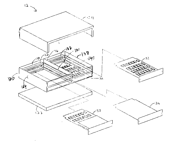
Referring to Fig. 5, multimedia expansion unit 12
includes housing 120, power subsystem 122 and cover 124.
Housing 120 includes media bus 24, which is located on
backplane 130, as well as connectors 132, which are
electrically connected to media bus 24. Connectors 132 are
oriented so that modules 30, 31, 34, 38 may be horizontally
inserted and thus connected to media bus 24. Housing 120
also includes support walls 134, 136, 138 on which are
attached guides 140. Guides 140 guide modules 30, 31, 34,
38 to connectors 132 as the modules are inserted, and
support the modules in housing 120 once the modules are
inserted. By providing expansion slots, modules may be
inserted into multimedia expansion unit 12 at the discretion
BC9-91-012 15
2059928
...
of the user, the only required module being media control
module 30. Accordingly, in the preferred embodiment there
are three slots remaining that may be used for multimedia
expansion cards such as programmable receiver 38 or graphics
accelerator module 34.
Bus interface circuit 51 of media control module 30 is
a separate card 51 which is connected to the remainder of
media control module 30 via system interface cable 130. The
architecture of card 51 corresponds to the I/O bus
architecture of computer 11. For example, the architecture
of card 51 corresponds to the IBM Micro Channel~
architecture if computer 11 is an IBM Personal System/2
personal computer. Alternatively, if computer 11 is an IBM
PC AT~ personal computer, then the architecture of card 51
corresponds to the AT architecture. Power subsystem 122
provides the power required to run any modules which are
inserted into multimedia expansion unit 12.
By providing a separate multimedia expansion unit, a
conventional computer system can be easily upgraded to
function as a multimedia system. Additionally, because
multimedia expansion unit 11 is separate from computer 11,
electromagnetic radiation can be contained within expansion
unit 12 so as to not interfere with the operation of the
computer. Also, because power base 122 is distributed
across the bottom of housing 120 and is only powering
multimedia expansion unit 12, thus requiring a relatively
small power supply, there is no need for any additional
cooling fans as heat generated by the relatively small power
supply may be passively dissipated. Because system
interface circuit 51 may be changed to suit individual
computer systems, multimedia expansion unit 12 may be used
with computer systems having different I/O architectures
merely by changing the architecture of system interface
circuit 51.
Other Embodiments
Other embodiments are within the following claims.
For example, the control information which controls the
switching of bus interface circuits 39 may be provided by
computer 11 rather than media control module 30.