Note: Descriptions are shown in the official language in which they were submitted.
2 06 0046 10812
IMAGE RECORDING MACHINE
BACKGROUND OF T~IE INVENTION
(Field of the Invention)
The present invention relates to a recording device,
such as a facsimile machine utilizing electrophotography,
and in particular to a mechanism for accurately positioning
a transfer charger with respect to a photosensitive drum.
(Prior Art)
A conventional electrophotographic recording device is
provided with a housing comprised of a lower cover and an
upper cover pivotable with respect to the lower cover for
opening and closing, a photosensitive drum~mounted to the
upper cover, and a transfer charger mounted to the lower
cover. A pair of guide plates are provided to guide
recording paper to the gap between the photosensitive drum
and the transfer charger. The guide plates are mounted to
the lower cover.
The gap between the cylindrical surface of the
photosensitive drum and the transfer charger must be
accurately adjusted in order to achieve a satisfactory
transfer of the toner image and obtain a picture (printout)
of a good quality. For instance, the gap is about 1 to 2 mm
and the permissible error is ~ 0.1 mm. But this is
dlfficult because the upper cover and the lower cover to
2060046 10812
which the photosensitive drum and the transfer charger are
respectively mounted are assembled such that they are
movable for opening and closing. Moreover, the exit part o~
the guide plates must be aligned with the gap between the
photosensitive drum and the transrer charger in order to
avoid paper jamming. But this again is requires delicate
and time-consuming adjustment. Providing mechanism for the
accurate positioning of these components may unacceptably
increase the cost of the recording device.
SUMMARY OF THE INVENTION
The invention aims at solving the above problems, and
its object is to provide a recording device in which the gap
between the cylindrical surface of the photosensitive drum
and the transfer charger is maintained constant, and
alignment between the guide plates and the gap between the
photosensitive drum and the transfer charger is ensured with
ease, and is also inexpensive.
A recording device according to the invention
comprises:
a housing comprised of a lower cover and an upper cover
pivotable with respect to the lower cover for opening to
permit access to the interior of the housing, and closing to
prevent access to the interior of the housing;
a photosensitive drum mounted to the upper cover and
having a cylindrical surface;
a
2060046 10812
a transfer charger being mounted to the lower cover;
a paper guide assembly having one part adfacent the
transfer section and guiding the recording paper to the
transfer section;
support rollers rotatably mounted on said one part of
the paper guide assembly so as to be engageable with axial
ends of the photosensltive drum;
said transfer charger being movable together with the
paper guide assembly; and
means for resiliently pressing the transfer charger
toward a photosensitive drum;
whereby when the upper cover is closed the
photosensitive drum is caused to abut on the support
rollers, and the gap between the cylindrical surface of the
photosensitive drum and the transfer charger is determined
by abutment of the support rollers on the cylindrical
surface of the photosensitive drum.
In the invention, by the action of the support rollers
with which the cylindrical surface of the photosensitive
drum is brought into contact, the gap between the
cylindrical surface of the photosensitive drum and the
transfer charger is maintained constant. Moreover, because
the relative position between the paper guide assembly and
the transfer charger is maintalned constant, alignment
between the exit part of the paper guide assembly and the
2060046
10812
gap between the photosensitive drum and the transfer charger
is ensured. As a result, a satisfactory toner image
transfer is achieved, and paper ~amming is avoided.
BRIEF DESCRIPTION OF THE DRAWINGS
Fig. 1 is a schematic sectional view of a recording
device of the invention, in the state in which it is closed.
Fig. 2 is a schematic sectional view of a recording
device of the invention, in the state in which it is opened.
Fig. 3 is a sectional view showing a pertinent part of
the recording device of an embodiment of the invention.
Fig. 4 is a perspective view showing part of the lower
paper guide assembly.
Fig. 5 is a perspective view showing the transfer
charger.
Fig. 6 is a sectional view showing engagement between a
hook on the paper guide assembly and a perforation on a
plate spring fixed to the lower cover.
Fig. 7 is a sectional view showing a pertinent part of
the recording device of another embodiment of the invention.
DETAILED DESCRIPTION OF THE PREFERRED EMBODIMENTS
An embodiment of the invention will now be described
with reference to Fig. 1 to Fig. 6.
The recording device of the illustrated embodiment is a
20600~6
10812
facsimile machine, and comprises an electrophotography
system 40, and a paper feed system 30, which are
accommodated in or attached to a housing formed of an upper
cover la and a lower cover lb. The housing can be opened
and closed by rotatlng the upper cover la relative to the
lower cover lb about a shaft lc. Some of the components are
attached to the upper cover la while others are attached to
the lower cover lb.
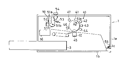
Referring first to Fig. 1 and Fig. 2, when the upper
cover la is closed, it is latched by a latch mechanism 50.
The latch mechanism comprises a hooked lever 51 which is
pivotably supported at a pivot axis 51b by the upper cover
la and has a hook 51a, and a notch 52 which is formed in the
lower cover lb and with which the hook 51a of the hooked
lever 51 is engageable. A tension spring 53 has one end
fixed to the upper cover la and the other end connected to
the lever 51 on the opposite side to the hook 51a with
respect to the pivot axis 51b thereby to provide a biasing
force to keep the engagement between the hook 51a and the
notch 52 once the engagement is established. To release the
engagement for opening the upper cover la, a press button 54
extending through the upper cover la is pressed. Then, the
upper cover la is lifted by a sprin~ 55 at the pivot shaft
lc .
The electrophotography system 40 comprises a
2060046
10812
photosensitive drum 41, which is rotatably mounted to the
upper~over la, and rotates in a direction indicated by arrow
Rp. Durlng the rotation its cylindrical surface 41a having
a photosensitive layer successively passes by a charger 42,
an exposure device 43, a developer 44, a transfer charger
12, a cleaning device 46 and a discharger 47.
The charger 42 uniformly charges the cylindrical
surface 41a of the photosensitive drum 41.
The exposure section 43 exposes the cylindrical surface
41a of the photosensitive drum 41 to a pattern of light,
thereby to form an electrostatic latent image on the surface
of the photosensitive drum 41.
The developer 44 forms a toner image corresponding to
the electrostatic latent image on the cylindrical surface
41a of the photosensitive drum 41.
The location where the transfer charger 12 faces the
photosensitive drum 41 forms a transfer section 45. At the
transfer section 45, recording paper 2 is brought into
contact with the cylindrical surface 41a of the
photosensitive drum 41, and the toner image is transferred
from the photosensitive drum 41 to the recording paper 2.
The transfer charger may comprise a corona charger
which applies electrostatic charges (of a polarity opposite
to the polarity of the charges forming the electrostatic
latent image) to the recording paper 2 by corona discharge,
2060046
10812
and thereby attracts the toner image on the photosensitive
drum 41 to the recording paper 2.
The cleaning device 46 removes any residual toner from
the photosensitive drum 41. The discharger 47 removes any
residual electrostatic charge from the photosensitive drum
41.
The paper feed system 30 comprises a paper cassette 3,
which is removably mounted to the lower cover lb, and
accommodates recording paper 2 consisting of a stack of cut
sheets.
A pick-up roller 7 picks up the recording paper 2 one
sheet at a time from the cassette 3.
The recording paper 2 that has been picked up is
conveyed through the conveyance path to the transfer section
45. Provided by the conveyance path are guide plates 22a
and 22b, a turn roller 18, an auxiliary roller 19, movable
guide plates lOa and lOb, a fixed guide plate 23, register
rollers 8a, 8b, and a paper guide assembly 11.
The auxiliary roller 19 is pressed against the turn
roller 18 by means of a movable guide plate 20, and as the
turn roller 18 rotates, it drives the auxiliary roller 19,
thereby to feed the recording paper 2 having reached the
turn roller 18, to the register rollers 8a and 8b.
The register rollers 8a and 8b are mounted on the lower
cover lb. The register roller 8b is pressed against the
2060046
10812
register roller 8a so that they pinch the recording paper 2
between them with a high pressure, and feeds the recording
paper 2 and ensures that the recording paper 2 be moved
forward, at a speed identical to the peripheral speed of the
photosensitive drum 41.
The paper guide assembly 11 guides the recording paper
2 having passed the register rollers 8a and 8b to the
transfer section 45. For this purpose, an entrance part of
the paper guide assembly 11 through which the recording
paper 2 having passed the register rollers 8a and 8b is
entered into the paper guide assembly 11 is near and in
alignment with the gap between the register rollers 8a and
8b, while the exit part of the paper guide assembly 11
through which the recordlng paper 2 is fed from the paper
guide assembly 11 to the transfer section 45 is in alignment
with the transfer section 45, in particular the gap between
the cylindrical surface 41a of the photosensitive drum 41
and the transfer charger 12~
At the transfer section 45, the recording paper 2 is
brought into contact with the cylindrical surface 41a of the
photosensitive drum 41.
The recording paper 2 onto which the toner image has
been transferred is separated from the photosensitive drum
41, and is then passed to a fixing device 16, where the
toner image is fixed.
2060046
10812
The paper guide assembly 11 of this embodiment
comprises a lower guide plate lla having a substantially
flat, horizontal part llc extending in the direction of the
paper transport and a pair of vertical parts lld and lle
extending vertically from respective edges of the horizontal
part llc, and an upper guide plate llb fixed to the lower
guide plate lla. A transport path for the recording paper 2
is formed between lower and upper guide plates lla and llb.
The ends of the guide plates lla and llb near the register
rollers 8a and 8b which are ad~acent to each other form the
entrance part of the paper guide assembly 11. The opposite
ends of the guide plates lla and llb which are also ad~acent
to each other form the exit part of the paper guide assembly
11 .
A pair of rod-shaped transfer charger pressing members
llf and llg extend along the respective edges of the
horizontal part llc of the lower guide plate lla. A pair of
arms llh and lli extend in parallel with the pressing
members llf and llg, and extend along and are foined with
the pressing members llf and llg. A hook llJ is fixed to
the vertical part lld.
The lower guide plate lla is fixed by screws to the
pressing members llf and llg, which in turn are fixed to the
arms llh and lli. One ends of the arms llh and lli are
pivotably supported at the axis 8ax of the register roller
2060046
10812
8a, so that the entlre paper guide assembly 11 is rotatable
about the axis 8ax of the register roller 8a.
The pressing members llf and llg are disposed to abut
on the upper surface 12a at first and second ends 12c and
12d of the transfer charger 12.
The hook 11~ is engageable with a perforation 39a (Fig.
6) in a vertically extending portion 39b of a plate spring
39 fixed to the lower cover lb. This engagement is attained
when the paper guide assembly 11 is pressed downward from
the above. By virtue of this engagement, the paper guide
assembly 11 is protected from undesirable disengagement.
The engagement is released by pulling the plate spring 39
laterally outward (to the right in Fig. 6).
The transfer charger 12 is mounted on the lower cover
lb. Specifically, it is resiliently supported by a plate
spring 32 interposed between the lower surface 12b of the
transfer charger 12 and the lower cover lb to provide a
biasing force to push up the transfer charger 12.
The transfer charger 12 is protected from undesirable
detachment by means of a hook 12e fixed to the first end 12c
and a perforation 38b in a vertical part 38b of a plate
spring 38 fixed to the lower cover lb, and a hook 12f on the
bottom surface 12b of the transfer charger 12 and near the
second end 12d of the transfer charger 12 and a perforation
37a of an engagement member 37 fixed to the lower cover lb.
2060046
10812
Support rollers 15 are provided on the pressing members
llf and llg, at parts ad~acent the cylindrical surface 41a
of the photosensitive drum 41 and to extend inward from the
inner surfaces of the pressing members llf and llg. The
support rollers 15 are engageable with the cylindrical
surface 41a at the axial ends of the photosensitive drum 41.
The support rollers 15 are short in the direction of
the axis of the photosensitive drum 41 and are provlded at
ends of the cylindrical surface 41a outside the area in
which the image is formed, so that they do not damage the
image and do not obstruct the transfer of the toner image.
When the upper cover la is open, the support rollers 15
are not in abutment with the photosensitive drum 41, so the
paper guide assembly 11 is free to be rotated upward about
the axis of the register roller 8a, and the transfer charger
12 is lifted by the plate spring 32 to the height determined
by the lifting force of the plate spring 32 and the weight
of the transfer charger 12 and the moment of the paper guide
assembly 11.
When the upper cover la is closed, the photosensitive
drum 41 is brought into contact with the support rollers 15,
mounted on the paper guide assembly 11, which pushes down
down the transfer charger 12, and because the transfer
charger 12 is supported by the plate spring 32 (which
thereby gives an upward force), the transfer charger 12 is
2060046
10812
pressed down resiliently by the photosensitive drum 41, and
the gap between the cylindrical surface 41a of the
photosensitive drum 41 and the transfer charger 12 is
maintained constant. Moreover, the paper guide assembly 11
and the transfer charger 12 are engaged (by abutment between
the pressing members llf and llg and the upper surface 12a
of the transfer charger 12) with each other, so the
alignment between the paper guide assembly 11 (in particular
its exit part) and the gap between the cylindrical surface
41a of the photosensitive drum 41 and the transfer charger
12 is ensured.
Since the paper guide assembly 11 is rotatable about
the axis 8ax of the register roller 8a, the entrance part of
the paper guide assembly 11 is kept in alignment with the
gap between the register rollers 8a and 8b, so the paper
feeding is achieved without trouble.
Fig. 7 shows another embodiment of the invention. In
this embodiment, a paper guide assembly 61 used in place of
the paper guide assembly 11 of the embodiment of Fig. 1 to
Fig. 6, comprises a lower guide plate 61a which is similar
to the lower guide plate lla but is provided with an
entrance inclined part llaa, an upper guide plate 61b
similar to the upper guide plate llb, a pair of transfer
charger pressing members 61g, and support rollers 65a and
65b. Only one pair of support rollers 65a and 65b which
2060046
10812
engage the cylindrlcal surface 41a at one end of the
photosensitive drum 41 are shown, but another pair of
support rollers are also provided to engage the cylindrical
surface 41a at the other end of the photosensitive drum 41.
The pressing members 61g abut on the upper surfaces at the
respective ends of the transfer charger 12, which is
resiliently supported by the spring 32. The pressing
members 61g of this embodiment are also engageable, at their
parts near the entrance part of the paper guide assembly,
with a supporting table 62.
When the upper cover la is open, the paper guide
assembly 61 is supported by engagement of the pressing
members 61g with the supporting table 62 as well as the
abutment of the pressing members 61g with the transfer
charger 12.
When the upper cover la is closed, the respective ends
of the photosensitive drum 41 are caused to abut on the pair
of the support rollers 15a and 15b, at different positions
along the circumference of the photosensitive drum 41, while
the transfer charger 12 is resiliently supported by the
plate spring 32. As a result, the paper guide assembly 61
is held at such a position that the supporting rollers 65
are pressed against the photosensitive drum 41, and floats
from the supporting table 62.
The gap between the photosensitive drum 41 and the
2060046
10812
transfer charger 12 ls thus maintained constant. Moreover,
the alignment between the exit part of the paper guide
assembly 61 and the gap between the photosensitive drum 41
and the transfer charger 12 is maintained constant.
The relative position between the entrance part of the
paper guide assembly 61 and the gap between the register
rollers 8a and 8b is changed a little in accordance with the
movement of the paper guide assembly 61, e.g., if the
position at which the photosensitive drum differs from the
designed position, the photosensitive drum is eccentric, or
the photosensitive drum has any surface irregularity or
undulation. But the alignment at the entrance part of the
paper guide assembly need not be so accurate as at the exit
part, because what is required at teh entrance part is to
ensure that the recording paper be introduced into the space
between the guide plates. Even if there is a small
misalignment, the recording paper can be led into the space
between the guide plates, without causing paper ~amming.
Moreover, the provision of the entrance expanded part 61aa
further alleviates the requirement on the alignment.
Although the invention has been described with
reference to specific embodiments, various modifications can
be made without departing from the scope of the invention.
The invention is not limited to a facsmile machine, and
is also applicable to other recording device such as a
2060046
10812
printer and a copier.
As has been described, according to the invention, the
paper guide assembly has a member pressing the transfer
charger and support rollers in contact with the surface of
the photosensitive drum, and the transfer charger is
resiliently pushed toward the photosensitive drum, so the
gap between the photosensitive drum and the transfer charger
is maintained constant, and the relative position between
the exit part of the paper guide assembly, and the
photosensitive drum and the transfer charger is maintained
constant. Accordingly, satisfactory transfer of toner image
is ensured. Moreover the structure is not complicated, and
the cost of the device is not expensive.