Note: Descriptions are shown in the official language in which they were submitted.
_ ._
j
HT4CKGFtOUPID of ~r~~. xrrv~rrmao~r
The present invention relates to a magneto-optical recording
medium, and particularly a magneto-optical recording medium of high
resolution.
In a magneto-optical recording and reproduction method,
local heating by irradiation with laser light is carried
out to
form informatiorx record pits, or bubble domains, and the
recorded
information is read through a magneto-optical interaction,
i.e, the
i
Kerr effect or the Faraday effect. When this method is
adopted,
increasing the density of magneto-optical recording may
be
accomplished by reducing the size of the record pits. In
such a
case, a problem arises as to the resolution (resolving
power) in
reproduction. The resolution is determined by the laser
wavelength
a and the numerical aperture N.A. of an objective lens
which are
used for reproduction.
A conventional magneto-optical recording and reproduction
system will now be explained with reference to Figure 3..
Figure
1A shows a schematic top plan of a record pattern, in which
a
magneto-optical recording medium 3 such as a magneto-optical
disk
has record pits 4 (hatched areas) formed, for instance,
according
to two-valued information "o" and "1'", in a land portion
?. bounded
on both sides by grooves 1, for example. The method of
reproduction in use of such a magneto-optical recording
medium will
be explained, with reference to the case where the beam
spot of
'.!p'P,k%va:T,'~~
reading laser light incident an the magneto-optical recording
medium 3 is a circular spot, as is denoted by reference
sign 5.
When the pit interval is so selected that only one record
pit 4 can
be present in a single beam spot 5, as shown in Figure
1A, each
area irradiated with the reading laser beam will exhibit
either of
two kinds of status. Namely, the irradiated area has either
one
record pit 4 or no record pit in the beam spot 5, as respectively
2
., __
~:..~_a...; A
shown in Figure 1B or 1C. Where the record pits 4 are arranged
at
regular intervals, therefore, an output waveform obtained
from the
recording medium 3 may be one that is alternatingly positive
and
negative with respect to a reference level 0; fox instance,
the
output waveform may be a sinusoidal one, as shown in Figure
1D.
On the other hand, where the record pits ~ are arranged in
high density as shown in a schematic top plan of a record
pattern
in Figure 2A, a plurality of. record pits 4 come under the
beam spot
simultaneously. Referring to three successive record pits
4a,
' 4b and 4c, for instance, the reproduction output obtained
when the
adjacent record pits 4a and 4b are located in a single beam
spot
5 does not differ from the reproduction output obtained when
the
record pits 4b and 4c are located in the beam spot 5, as shown
in
Figures 2B anct 2C. Therefore, the reproduction output waveform
will be, for example, rectilinear as shown in Figure 2D, and
the
t b
e
reproduction outputs in the above two situations canno
distinguished from each other.
Thus, in the magneto-optical recording and reproduction
system generally used in the prior art, the record pits 4
formed
on the magneto-optical recording medium 3 are kept as they
are
during reading of recorded information. Wherefore, even if
high-
density recording, i.e. formation of record pits in a high
density,
is accomplished, a high S/N (C/N) cannot be obtained due to
limitations as to resolution in reproduction. In short,
:,1. ..:_:rs;::l
satisfactory high density recording and reproduction.cannot
be
achieved according to the conventional magneto-optical recording
and reproduction system.
In order to solve the S/N (C/N) problem, it is necessary to
improve the resolution (resolving power) in reproduction, and there
arises another problem that the laser wavelength a, the numerical
aperture N.A. of the objective lens, etc. impose restrictions on
3
~~~a~~
the resolving power. As a countermeasure against these problems,
the present applicant has previously proposed a superhigh-
resolution (superhigh resolving power) magneto-optical system for
recording and reproduction (the system will be hereinafter referred
to as "MSR") (Refer to, for example, Unexamined Japanese Patent
Publication IiEI 1-2256Ei5 entitled "Magneto-optical recording and
reproduction process" and Unexamined Japanese Patent Publication
HEI 1-229395 entitled "Signal reproduction process for magneto-
optical recording media", incorporated herein).
An explanation will now be given of the MSR. In the MSR,
a temperature distribution produced by relative movement of a
magneto-optical recording medium and a reproducing beam spot 5 is
utilized so as to ensure that record pits 4 on the magneto-optical
recording medium will, in reproduction, be generated only in a
predetermined temperature region, resulting in a higher :resolution
,Yv, ~ ..,
in reproduction.
Examples of the MSR system include so-called relief type and
extinction type reproduction systems.
First, the relief type MSR system will be explained with
reference to Figure 3. Figure 3A is a schematic top plan showing
a record pattern on a magneto-optical recording medium 10, and
Figure 3B is a schematic sectional view showing a magnetization
mode of the same. As shown in Figure 3A, the magneto-optical
recording medium 10 is moved in the direction of arrow D, relative
.::;.s~.ie'~ i
to a laser beam spot 5. As shown in Figure 3B by way of example,
the magneto-optical recording medium 10 such as a magneto-optical
disk used here comprises at least a reproduction layer 11 composed
of a perpendicular magnetization film and a recording layer 13;
preferably; the recording medium 10 further comprises an
intermediate layer 12 interposed between the layers 11 and 13.
Arrows in the layers 11, 12 and 13 each represent schematically the
4
..
~I'~ta"~st',~
orientation of a magnetic moment. In the example Shawn, the
downward orientation corresponds to an initialized state.
Information record pits 4 in the form of magnetic domains are
formed at least in the recording layer 13 by upward magnetization,
as viewed in the figure.
In a reproduction mode of the magneto-optical .recording
medium 10, first an initializing magnetic field Hi is applied
externally, whereby the reproduction layer 11 is initialized by
being magnetized in a downward orientatian as seen in Figure 3B.
Namely, the record pits 4 in the reproduction layer 11 disappear.
In this case, in the areas where the record pits 4 are present, the
magnetization directions of the reproduction layer 11 and the
recording layer 13 are kept opposite to each other by a domain wall
produced at the intermediate layer 12, so 'that the record pits 4
are left as latent record pits 41.
on the other hand, a reproducing magnetic field Hr in the
opposite direction to the initializing field Hi is applied to the
magneto-optical recording medium 10, at least in a reproduction
area thereof. As the medium 10 in this condition is moved, the
region including the latent record pits 41 initialized as above
comes to fall under the beam spot 5. Then, when the portion heated
by irradiation with the laser beam is moved to the front end side
of the beam spat 5, i.e. leftward in Figure 1, a substantially
high-temperature region 14 encircled with broken line (a) and
,;:~,;j
hatched in the figure is generated on the front end side of the
spot 5. In the region 14, the domain wall at the intermediate
layer 12 is lost, and the magnetization of the recording layer 13
is transferred to the reproduction layer 11 by exchange force. As
a result, the latent record pits 41 present in the recording layer
13 are duplicated in relief in the reproduction layer 11, as
reproducible record pits 4.
Therefore, the record pits 4 can be read by detecting the
rotation of the polarization plane caused at the beam spot 5 by the
Kerr effect or the Faraday effect, according to the magnetization
direction of the reproduction layer 11. Furthermore, in a law-
temperature region 15 other than 'the high-temperature region 14 in
the beam spot 5, the latent record pit 41 is not duplicated in
relief in the reproduction layer 11. In the beam spot 5,
consequently, the readable record pit 4 is present only in the
hatched, narrow, high-temperature region 14. As a result, even in
the case of such a recording density that a plurality of record
pits 4 come under the beam spot 5 at the same time, namely, even
in a magneto-optical recording medium 10 for high-density
recording, it is possible to read only a single reeard pit 4, and
hence to achieve high-resolution reproduction.
In order to perform such reproduction, the initializing
magnetic field Hi, reproducing magnetic field Hr as well as the
coercive force, 'thickness, magnetization and domain wall energy of
each magnetic layer, etc. are selected according to the
temperatures of the high-temperature region 14 and low-temperature
region 15 in the beam spot 5. Namely, where the reproduction layer
12 and the recording layer 13 nave coercive forces H~, and H~"
thicknesses h, and h" and saturation magnetization (MS) values MS,
and MS" respectively, the condition for initializing the
reproduction layer 11 only is given by the following Equation 1:
i (Equation 1) Hi > H~, + Q"2/2M,,h,
where a"Z is the interfacial domain wall energy between the
reproduction layer I1 and the recording layer 13.
Also, the condition for the information recorded in the
recording layer 13 to be maintained under 'the magnetic field is
given by Equation 2:
(Equation 2) Hi < H~, = a"Z/2Ms,h,
s
r~: f,---:~i
Further, :in order that the domain wall at the intermediate
layer 12 between the reproduction layer 11 and the recording layer
13 may be maintained after passage under the initializing magnetic
field Hi, the condition expressed by the following Equation 3 is
_ required.
(Equation 3) H~, > a"2/2Ms,h,
As for the temperature T" selected to be in the high-
temperature region 14, the condition expressed by 'the following
Equation 4 should be satisfied.
(Equation 4 ) H~, - awz/2l~mh, < Hr < H~, + o"2/2Mt,h,
By application of a reproducing magnetic field Hr which
fulfills the condition of Equation 4, the magnetization of the
latent record pits 4 in the recording layer 13 can be transferred
to the reproduction layer 11, that is it is duplicated in relief
as record pits 41 in the reproduction layer 11, and only in the
F:
area where the domain wall formed by the intermed9.ate layer 12 is
present.
Although the magnetic recording medium 10 used for 'the MSR
system above has been explained with reference to a three-layer y
structure comprising the reproduction layer 11, intermediate layer
12 and recording layer 23, a four-layer structure may also be
adopted in which a reproduction sub-layer 31 is provided on the.
side of the intermediate layer 12 with respect to the reproduction
layer 11, as illustrated by a schematic sectional view thereof in
,:;_..:...; . i
Figure 4.
The reproduction sub-layer 31 functions in aid of the
characteristics of the reproduction layer 11, and compensates for
the coercive force of the reproduction layer 11 at room
temperature. The presence of the reproduction sub-layer 31 ensures
that the magnetization of the reproduction layer 11 aligned by the
initializing magnetic field Hi can exist in stable fashion in the
7
presence of the domain wall, and the coercive force of the
reproduction layer 11 is reduced drastically in the vicinity of the
' reproduction temperature. Thus, the domain wall is confined in the
intermediate layer 12 and is permitted to spread into the
reproduction sub-layer 31 to finally reverse the magnetization of
the reproduction layer 11. This is accompanied by disappearance
of the domain wall. As a result, the recGrd pits in the recording
layer 13 can be duplicated in relief in the reproduction layer 11
in an improved manner.
i When the four-layer structure including the reproduction
sub-layer 31 is adopted, the coercive force H~~ of the reproduction
layer 11 is replaced by H~a defined by the following Equation 5, and
~Hzf Msihi by Qwz~ ~Msihi -E M,ishis )
Equation 5)
Hca - IM.~hiH~t 'f' Msmhm~'I~m)~~M.ih~ '~" Msa~hi.)
in the fore oin relief t a MSR H < F1 < H
( g g Yp I ~I CA c1s)
where M,,~, H~,, and h,~ respect:ively represent the magnetization,
coercive force and thickness of the reproduction sub-layer 31.
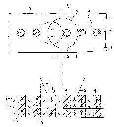
In the next place, the extinction type MSR will be explained
with reference to Figure 5. Figure 5A is a schematic top plan
showing a record pattern on a magneto-optical recording medium 10,
and Figure 5B is a schematic sectional view showing a magnetization
mode thereof. In Figures 5A and 5B, component parts corresponding
to those in Figures 3A and 3B are denoted by the same reference
,::::j
signs as used in Figures 3A and 3B, and the explanation of those
parts will not be repeated. This MSR system does not require an
initializing magnetic field Hi.
In a reproduction mode of the magneto-optical recording
medium 10, the condition expressed by the following Equation 6 is
fulfilled in a high-temperature region 14. Thus, the magnetization
in the high-temperature region 14, even if in a laser beam spot 5,
8
2~~ ~~
.~~a~
is aligned in the downward direction by a reproducing magnetic
field Hr applied externally. Consequently, record pits 4 in a
reproduction layer 11 disappear. Thus, the extinction type MSR
system is designed so that reproduction can be performed only for
the record pits 4 present in a low-temperature region 15 located
in the beam spot 5, thereby offering an improved resolution.
(Equation 6) FIr > H~, -E a"2/2M"h,
In this case, however, conditions such as the coercive force
of a recording layer 13 are set so that even after the extinction
(disappearance) of the record pits 4 in the reproduction layer 11,
the record pits 4 in the recording layer 13 are left as latent
record pits Q1. .It is thereby ensured that, at room temperature,
the magnetization of the recording layer 13, namely, the
information pits 4 in the layer 13 are transferred to the
reproduction layer 11 and held in the reproducible state.
~,- .,
~~t
According to the relief type and extinction type MSR systems
described above, the record pits located in a part of the area of
the reproducing laser beam spot are reproduced, so as to attain an
enhanced resolution in reproduction.
Furthermore, the above relief type and extinction type MSR
systems may be used in combination. In that case, a magneto-
optical recording medium to located under a beam spot 5 is provided
with a temperature distribution in which temperature becomes lower
from the forward side toward the backward side with respect to the
moving direction of the recording medium relative to the beam spot
5, resulting in the formation of a high-temperature region 14, an
intermediate-temperature region 16 and a low-temperature region 15
in the area of the beam spat 5, as shown in Figure 6. The high-
temperature region 14 is made to have the function of the
extinction type as explained above with reference to Figure 5,
while the intermediate--temperature region 16 and the low-
9
temperature region 15 are made to function respectively as the
high-temperature region 14 and low-temperature region 15 as
explained above with reference to Figure 1.
According to the MSR system employing both the relief type
and the extinction type in combination, the record pit 4 to be
developed in relief in the reproduction layer 11, represented by
hatching in Figure 6, can be present only in the limited,
intermediate-temperature region 16 defined between the high-
temperature region 14 and the low-temperature region 15. A higher
resolution can be thereby achieved.
It is thus possible, according to the MSR systems, to
achieve superhigh-resolution reproduction without any restrictions
imposed by the wavelength a of the laser beam or the numerical
aperture N.A, of the objective lens.
Accordingly, the MSR systems enable a wavelength selection
for the reading light to be made taking into account the magneto-
optical effect, the temperature rise due to light absorption, the
sensitivity of a light detector and the like, without adhering to
the use of a shorter wavelength:
In other words, a semiconductor laser mgn~ wzLn a
comparatively long wavelength (780 nm), for example, can be used
as the reading light, to obtain a high reproduction resolution.
&UM~3A~t3C OF' THE INVENTION
-K~:::~.:_>'~~ It is accordingly an object of this invention to provide a
magneto-optical recording medium with which reproduction based on
the foregoing relief type MSR system or the combined relief-
extinction type MSR system, especially reproduction with a pit
length of 0.4 ~,m and a high C/N of at least about 40 dB, can be
performed securely and in stable fashion.
~~"1
It is an object of the invention to assure reproduction with
a high resolution.
~ According to the invention, a reproduction layer 11 is
composed mainly of GdFeCo and has a saturation magnetization of at
least 450 emu/cc and a coercive force of not more than 4 k0e. A
recording layer is composed mainly of TbFeCo, and has a coercive
.force of at least 5 kOe. The recording layer has a magnetization
of not more than 300 emu/cc if it is a transition metal-predominant
film, and has a magnetization of not more than 200 emu/cc when it
is a rare earth-predominant film.
BRIEF DESCRIPTIOP1 OF THE DRAT~IIIdGB
Figure 1 is an illustration of a reproduction mode of
magneto-optical recording according to the prior art;
Figure 2 is an illustration of a reproduction mode of
~r~,;~,,~ magneto-optical recording according to the prior art;
Figure 3 is an illustration of one relief type NlSR;
Figure 4 is an illustration of another relief type MSR;
Figure 5 is an illustration of one extinction type MSR;
. Figure 6 is an illustration of another extinction type MSR;
Figure 7 is a schematic sectional view of one embodiment of
the magneto-optical recording medium according to this invention;
Figure 8 is a perspective view illustrating a reproduction
mode of one embodiment of the magneto-optical recording medium
according to this invention;
Figure 9 is a graph showing the relationship between a
magnetization of the reproduction layer and C/N far the magneto-
optical recording medium according to this invention;
Figure 10 is a graph showing the relationship between
magnetization of a reproduction sub-layer and C/N for the magneto-
optical recording medium according to this invention;
11
_ ~~0'~4~~
. _,
:::_~;:i
Figure 11 is a graph showing the relationship between
magnetization of the intermediate layer and C/N for the magneto-
optical recording medium according to this invention;
Figure 12 is a graph showing the relationship between
magnetization of the recording layer and C/N for the magneto-
optical recording medium according to this invention; and
Figure 13 is a graph showing the relationship between a
thickness of the reproduction sub-layer and C/N for the magneto-
optical recording medium according to this invention.
DESCRIPTTOI~T OF THE PREFERRED EMEODIMENTs
Referring now to Figure 7, there is schematically shown, in
section, a magneto-optical recording medium 100, which comprises
~, ,,i at least a reproduction layer 110, a recording layer 130 and an
intermediate layer 120 interposed therebetween, the layers being
'~"''r~ so stacked that the adjacent ones thereof are magnetically coupled,
ri
and from which recorded signals are read through changing the state
of magnetization of the reproduction layer under irradiation with
' reading light. It is assumed 'that the reproduction layer 110 and
i
the recording layer 130 have saturation magnetization (M~} values
of M,, and M~" and coercive force (H~) values of H~, and H~3,
respectively.
According to this invention, in the just°mentioned magneto
optical recording medium, the reproduction layer 110 comprises a
;;:,,.~,~.~:.,~:~ rare earth-transition metal magnetic layer containing GdFeCo
as a
main constituent, and satisfies M,, <_ 450 emu/cc and H~, 5 4 kOe at
room temperature.
The recording layer 13 comprises a rare earth-transition
metal magnetic layer containing TbFeCo as a main constituent,
satisfies H~3 >_ 5 kOe, and also satisfies either Ms, <_ 300 emu/cc or
12
0
M,, S 200 emu/cc, depending on whether the recording layer is a TM
(transition metal) rich film or an RE (rare earth) rich film.
Recording of information, or formation of record pits 4, on
the magneto-optical recording medium 100 according to this
invention is carried out at least in the recording layer 130. The
information recording can be made, for example, by the magnetic
field modulation system.
Reading of information from the magneto-optical recording
medium 100, for example a magneto-optical disk, having information
thus recorded as record pits 4 in the recording layer 130 is
carried out in the manner as shown in Figure 8, in which a linearly
polarized laser beam L of semiconductor laser light (wavelength 780
nm) is focused by an objective lens 71 on the medium 100 revolving
in 'the direction of arrow D, from the side of a substrate 20 as
explained with reference to Figure 1.
The record pit 4 is read by detecting 'the difference between
the rotation of the polarization plane in the pit area, especially
at the reproduction layer 110, by the Kerr effect and the
corresponding .rotation in the other (non-pit) areas.
A .reproducing field generating means 72 is provided by which
a reproducing magnetic field Hr, developed by a required DC
magnetic field orthogonal to the plane of the medium 10, is applied
to the area including the part of the medium 10 irradiated with the
beam spot 5 of the laser beam L.
On the other hand, an initializing field generating means
73 is provided by which a DC initializing magnetic field Hi,
directed opposite to the reproducing magnetic field Hr, is applied
to a part of the medium 10 not yet brought under the beam spot 5.
. With these arrangements, reproduction is carried out according to
the relief type MSR system as explained with reference to Figures
3 and 4, or according to a combination of the relief type and
13
extinction type as explained with reference to Figure 6; namely,
the reproduction is carried out by a reading system which at least
comprises developing (or duplicating) the record pits 4 in relief
into the recording layer 110.
An application of this invention to a magneto-optical disk
will now be explained.
As shown in Figure 7, the magneto-optical disk may be
fabricated by sequentially providing, as for instance by
sputtering, a dielectric film 23 composed of SiN or the like with
an exemplary thickness of 800 t1, a magneto-optical recording layer
21, and a protecti a film 25 composed of SiN or the like with an
exemplary thickness of 800 E1 on a light-transmitting substrate 20
formed of a glass, a polycarbonate resin, or the like .
The magneto--optical recording layer 21 may have a three-
layer structure which, as explained with reference to Figure 3,
comprises a reproduction layer 11, an intermediate layer 12 and a
recording layer 13 in successive magnetic coupling. However, a
four-layer structure which, as explained with reference to Figure
4, comprises a reproduction layer 11, a reproduction sub-layer 31,
an intermediate layer 12 and a recording layer 13 with successive
magnetic couplings may also be adopted. This produces an
advantageous effect in, for example, compensating for the coercive
force of the reproduction layer 11 at room temperature.
With reference to Figure 7, the reproduction layer 110,
reproduction sub-layer 31, intermediate layer 120 and recording
layer 130 constituting the magneto-optical recording layer 21 can
be formed by successive sputtering.
The reproduction layer 110 comprises, for example, GdFeCo
as a main constituent, to which Cr of the like may be added, as
required, for enhancing reliability, and Nd or the like for
adaptation to a shorter wavelength laser light. The thickness H,
14
~fl~i~~"i~
of the reproduction layer 110 is so selected that the layer 110 is
thick enough to obtain a sufficient Kerr effect in reproduction,
and that the required temperature distribution can be obtained
without needing an. excessively high reproduction power. Namely,
the thickness h, is selected in the range of 150 to 1000 A. The
Curie temperature T~, of the reproduction layer 110 is so selected
that the Kerr rotation angle BK is not deteriorated due to the
temperature rise caused by the irradiation with laser Iight for
reproduction. Namely, the Curie temperature T~, is selected, on a
functional basis, to be about 200°C or above. The saturation
magnetization M~, of the reproduction layer 110 is in 'the range of
0 < M,, <_ 450 emu/cc (at room temperature) in the case of TM-rich
film compositions, and in the range of 0 < M,, 5 350 emu/cc in the
case of RE-rich film compositions.
The reproduction sub-layer 31 is composed of a magnetic
layer whose main constituent is TbFeCo, for example, and which has
a saturation magnetization M,,, of 100 to 600 emu/cc in the case of
TM-rich film compositions (at room temperature). The coercive
force H~" of the reproduction sub-layer 31 is preferably 7 kOe or
below, provided that H~A defined by 'the above Equation 5 is not more
than 4 kOe. The Curie temperature T~" of the layer 31 is about 60
. to 100°C. The reproduction sub-layer 31 is constituted mainly of
a TbFeCo-based material, to which traces of Gd, Cr, Nd, Dy or AI
may be added so as to control the characteristics of the layer,
especially the temperature characteristic of the coercive force
Hm
The intermediate layer 120 is composed of a magnetic layer
consisting mainly of GdFeCo, for example. The saturation
magnetization M~Z of the layer 120 is in the range of 0 < M~Z <_ 700
emu/cc in the case of TM-rich film compositions, and in the range
of 0 < M,r <_ 200 emu/cc in the case of RE-rich film compositions.
Compensation temperature of the intermediate layer 120 may be 100°C
or below, and a film thickness h~ of not less than about 50 A may
be sufficient.
The recording layer 130 is composed of a magnetic layer of
which the main constituent is TbFeCo, for example, and the
saturation magnetization M,, is in the range of 0 < Ms, ~ 300 emu/cc
in the case of TM-rich film compositions and 0 < M,, <_ 200 emu/cc
in the case of ~2E-rich film compositions. For the recording layer
130 also, a thickness h, of not less than about 200 A may be
sufficient.
The saturation magnetization herein is represented by the
value at room temperature.
In use of the magneto-optical recording medium 100, namely,
with the magneto-optical disk having the construction as above,
reading of record pits through the Kerr effect from the
reproduction layer 110 is carried out by a magneto-optical
reproduction drive system as described with reference 'to Figure 8,
according to 'the principle explained with reference to Figures 3,'
4 and 6.
Embodiment 1
In the construction as described above with reference to
Figure 7, the dielectric film 23 was composed of an SiN film with
800 A thickness, and the reproduction layer 110 was composed of
.:.~.~;:1 GdFeCo (M,, - 225 emu/cc) in a thickness h, of 350 A. The
' reproduction sub-layer 31 was composed of TbFeCo (M,,, = 320 emu/cc)
in a thickness h,, of 200 la, with H~A = 3 kOe. The intermediate
layer 120 was composed of GdFeCo (M~Z = 200 emu/cc) in a thickness
hZ of 150 A, with H~Z = 800 (Oe) . The recording layer 130 was
composed of TbFeCo (M~, = 50 emu/cc in a thickness h, of 400 ~., with
16
a coercive force H~, > 15 kOe. In this manner, a 5.25-inch magneto-
optical disk was produced.
. The magneto-optical disk thus obtained in Embodiment 1 was
subjected to measurement of C/N versus magnetization M, of the
reproductian layer 110 at room -temperature, under the conditions
of a revolving speed of 2400 rpm, a linear velocity vL at radius
r = 30 mm of 8 m/sec, a signal freduency f = 10 MHz, namely a 0.8
~m pitch (pit length 0.4 ~tm), and a reading laser power Pr = 3.0
mW, with the composition of the reproduction layer 110 being
varied. The results are shown in Figure 9. It is seen from the
figure that C/N of 40 dB or above can be obtained at a
magnetization of 0 < Msl <_ 450 emu/cc with TM-rich film
compositions, and 0 < M" <_ 350 emu/cc with RE-rich film
compositions.
In Figure 9 and in Figures 10 to 12, which will be referred
to below, the magnetization is expressed in negative values for -the
RE-rich film compositions and in positive values for the TM-rich
film compositions.
Next, the magneto-optical disk obtained in Embodiment 1 was
subjected to another series of measurements of C/N under the same
conditions as above, with the composition of the reproduction sub-
i layer 31 being varied. Namely, measurement of C/N versus
magnetization M,,, of the layer 31 was carried out at room
temperature by varying the Tb content of TbFeCo, to give the
ra~~:~~: xj
results as shown in Figure 10. The results show that a C/N of 40
dB or above can be obtained at a magnetization of 100 to 600 emu/cc
j
with TM-rich film compositions.
In addition, the conditions of H~,, < 7 kOe and H~A < Hi (up
to 4 kOe) axe fulfilled.
17
_ __
Also, the magneto-optical disk obtained in Embodiment 1 was
subjected to a measurement of C/N under the same conditions as
above, with the composition of 'the intermediate layer 130 being
varied. Namely, measurement of C/N versus magnetization M,Z of the
layer 130 was carried out at room temperature by varying the Gd
content of GdFeCo, to give the results as shown in Figure 11. The
j
results show that a C/N of 40 dB or above can be obtained at M,2 <
i
700 emu/cc with TM-rich film compositions, and at M~Z <_ 200 emu/cc
with RE-rich film compositions.
Furthermore, the magneto-optical disk obtained according to
Embodiment 1 was subjected to a measurement of C/N under the same
conditions as above, with the composition of the recording layer
130 being varied. Namely, a measurement of C/N versus M,, was
carried out at .room temperature by varying the Tb content of TbFeCo
to give the results as shown in Figure 12. The results show that
a C/N of 40 dB or above can be obtained at a magnetization of 0 <
M,, <_ 450 emu/cc with TM-rich film compositions, and at a
magnetization of 0 < M~, <_ 350 emu/cc with RE-rich film
compositions.
Incidentally, the above GdFeCo, TbFaCo and the like are
ferromagnetic materials, in which the sublattice magnetization of
rare earth metals such as TbGd, etc. and the sublattice
magnetization of transition metals such as FeCo, etc. are always
opposite to each other. The saturation magnetization M, is the
ir:~s,::cyn~
balance of the two kinds of sublattice magnetization.
In this case, the saturation magnetization M, decreases with
increasing addition of rare earth (RE) to transition metal (TM),
and becomes 0 (zero) at a certain addition amount at which the
sublattice magnetizations of the TM and the RE are equal.
18
__ ~~~~t~'3
With further addition of RE, the sublattice magnetization
of the RE becomes greater than 'that of the TM, and the saturation
magnetization M, becomes larger.
Measurement of C/N was also carried out by varying the
thickness h" of the reproduction sub-layer. 31 in Embodiment 1. The
results are shown in Figure 13, from which it is seen that the film
thickness hl, does not have significant influence on the
characteristics of the recording medium.
As has been stated above, according to this invention it is
possible to obtain a high C/N of at least 40 dB. This achievement
is attributed to the assured functioning of the layers 110, 120,
130 and 31, by which latent record pits 41 in the recording layer
130 are transferred, or developed in relief, in a limited
temperature area 14, as described with reference to Figures 3 and
4, upon irradiation with reproducing laser light.
Besides, the intermediate layer 120 and the sub-layer 31 are
not limited to 'the rare earth-transition metal magnetic layers
described above, but can be composed of other various rare earth-
transition metal magnetic layers. The magneto-optical recording
layer according to this invention is not limited to the magneto-
I optical recording layer 21 of the four-layer structure described
in Embodiment 1, but may have a three-layer structure not
comprising the reproduction sub-layer 31. Further, this invention
is applicable to a variety of MSR systems based on the relief type
:~:?<a:,i::':i=~. i
and having, such as shown in the MSR system of Figure 4, the
reproduction layer 11, intermediate layer 12 and recording layer
13 as principal components of its structure.
As is clear from the above, the magneto-optical recording
medium 100 according to this invention, when applied to the relief
type MSR or to a combined relief-extinction type reproduction
system using the relief type MSR as part of the principle thereof,
19
i . .
i;~s.-,W i".k.
ensures a high C/N of at least 40 dB in high-density recording at
a recording frequency of 10 MHz. Therefore, this invention
produces a very large profit in practice.
Although various minor changes and modifications might be
proposed by those skilled in the art, it will be understood that
we wish to include within the claims of the patent warranted hereon
all such changes and modifications as reasonably come within our
contribution to the art.
~.~~'.a~"-