Note: Descriptions are shown in the official language in which they were submitted.
METHOD FOR DETERMINING FLU>D INFLUX OR LOSS
IN DRILLING FROM FLOATING RIGS
The present invention relates to a method for determining fluid influx or loss
when drilling wells from a floating rig, for example a drill ship or a semi-
submersible
rig.
In certain situations in the petroleum industry, oil bearing formations are to
be
found beneath the sea bed. Where the sea bed is up to 350 ft below the sea
level,
bottom supported drilling rigs such as jack-up rigs can be used. However, in
deeper
water it is not possible for the drilling rig to rest on the bottom and a
floating platform
must be used. Floating platforms such as drill ships or semi-submersible rigs
can
operate in much deeper water than bottom supported rigs but do suffer from
problems
in maintaining a steady positional relationship with the sea bed. While
horizontal
movements can be controlled to some degree by dynamic positioning systems and
anchoring, vertical movement or "heave" due to wave action remains.
It is current practise to utilise a drilling fluid or mud in petroleum or
geothermal
well drilling. The mud is pumped into the drillstring at the surface and
passes
downwardly to the bit from where it is released into the borehole and returns
to the
surface in the annular space between the drillstring and borehole, carrying up
cuttings
from the bit back to the surface. The mud also serves other purposes such as
the
containment of formation fluids and support of the borehole itself. When
drilling a
well, there exists the danger of drilling into a formation containing
abnormally high
pressure fluids, especially gas, which may pass into the well displacing the
mud. If this
influx is not detected and controlled quickly enough, the high pressure fluid
may flow
freely into the well causing a blowout. Alternatively, some formarions may
allow fluid
to flaw from the well into the formation which can also be undesirable.
Fluid influx (or a "kick") or fluid loss (lost circulation) can be detected by
comparing the flow rate of mud into the well with the flow rate of mud from
the well,
these two events being indicated by a surfeit or deficit of flow respectively.
However,
in floating rigs, heave motion effectively changes the volume of the flow path
for mud
flow to and from the well making the detection of kicks or lost circulation
difficult in
the short term.
A method and apparatus for detecting kicks and lost circulation is described
in
US 3 760 891 in which the return mud flow is monitored and the values
accumulated
over overlapping periods of time. By comparing the flow from one period with
that of a
previous period and comparing with preselected values, the flow rate change is
-1-
CA 02060736 2001-09-24
67524-3
2
determined. However, this technique is relatively slow to
determine anomalous flow situations.
It is an object of the present invention to
provide a method which can be used to effect real-time
correction of measured flow rates to compensate for rig
heave motion.
In accordance with the present invention, there is
provided a method of determining fluid influx or loss from a
well being drilled from a floating vessel and using a drill
string through which a drilling fluid is circulated such
that said fluid flows into the well via the drill string and
flows out of the well at the surface, the method comprising
the steps: (a) monitoring the flow of fluid from the well to
obtain a varying flow signal indicative of the variation in
flow from the well, (b) monitoring any heave motion of the
vessel to obtain a varying heave motion signal indicative of
said motion, (c) using the varying heave motion signal to
calculate an expected variation in said fluid flow from the
well due to said motion, (d) using the calculated expected
variation in flow to correct the varying flow signal to
compensate for any varying flow component due to said heave
motion thereby generating a compensated flow signal; and
(e) monitoring the compensated flow signal for an indication
of fluid influx or loss from the well.
By monitoring the heave motion of the vessel
separately from the flow movement, the observed flow can
easily be corrected to remove any effects of heave motion so
allowing faster correction and hence greater accuracy in
anomalous flow detection. Other rig motion components such
67524-3
CA 02060736 2001-09-24
2a
as roll which also affect the drilling fluid flow could also
be compensated for in a similar manner. Preferably, the
compensated signal is compared with the measured flow into
the well. The difference between these signals can be used
to raise alarms where necessary.
The flow measurement is typically obtained from a
flow meter in the fluid output from the well and the heave
motion is typically obtained from an encoder on a slip joint
in the marine riser. Flow into the well can be calculated
from the volume of mud pumped by the mud pumping system into
the well.
To determine whether the flow from the well is
anomalous, the compensated value is preferably compared with
an upper and/or a lower threshold to determine fluid influx
or loss respectively.
It is preferred that the calculations should be
performed simultaneously with continuous measurements and
can be on a time averaged basis if required.
According to another aspect the invention provides
a method of determining fluid influx or loss from a well
being drilled from a floating vessel and using a drill
string through which a drilling fluid is circulated such
that said fluid flows into the well via the drill string and
flows out of the well at the surface, the method comprising:
(a) monitoring the flow of fluid from the well to obtain a
varying signal indicative of the variation in flow from the
well, (b) monitoring any heave motion of the vessel over a
given period of time to obtain a time differentiated heave
motion signal indicative of said motion, (c) using an
adaptive filtering technique to obtain an adaptive filter
CA 02060736 2001-09-24
67524-3
2b
which models the relationship between said time
differentiated heave motion signal and said signal
indicative of the variation in flow from the well,
(d) determining with said adaptive filter an expected
variation in said fluid flow using a current value of said
time differentiated heave motion signal as an input to said
adaptive filter, said expected variation in said fluid flow
being the output of said adaptive filter, (e) using the
calculated expected variation in flow to correct the varying
flow signal to compensate for any varying flow component due
to said heave motion thereby generating a compensated flow
signal; and (f) monitoring the compensated flow signal for
an indication of fluid influx or loss from the well.
The invention will now be described, by way of
example with reference to the accompanying drawings in
which:
Figure 1 is a representation of a floating
drilling rig shown in schematic form;
Figure 2 shows an unprocessed plot of flow from
the well (gallons per minute (GPM) vs. seconds (S));
Figure 3 shows an unprocessed plot for heave
motion of the rig (relative vertical position in meters (m)
vs. seconds (S));
2~~~'~~~
- Figures 4 and 5 show spectral analyses of the signals from Figures 2 and 3
(power (P) vs. frequency (Hz);
- Figure 6 shows a coherence plot obtained using the special data of Figures 4
and S (coherence vs. frequency (Hz);
- Figure 7 shows a plot of a constant flow rate with heave motion
superimposed thereon;
- Figure 8 shows a plot of an increasing flow with heave motion
superimposed thereon; and
- Figure 9 shows a plot of differential flow derived from Figure 8 and
compensated for heave motion.
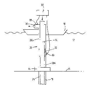
Referring now to Figure 1, there is shown therein a schematic view of a
situation
in which the present invention might find use. The rig shown therein has parts
omitted
for reasons of clarity and comprises a vessel hull 10 which is floating in the
water 12.
The vessel can be a drilling ship or semi-submersible rig or other floating
vessel and
can be maintained in position by appropriate means such as anchoring or
dynamic
positioning means (not shown). A drillstring 14 passes from the rig to the sea
bed 15,
through a BOP stack 16 into the borehole 18. The vessel 10 and BOP stack 16
are
connected by means of a marine riser 20 comprising a lower section 20, fixed
to the
BOP stack 16, and an upper section 20b fixed to the hull 10. The upper and
lower
sections 20a, 20b are connected by means of a telescopic joint or "slip joint"
22 to
allow heave movement of the hull 10 without affecting the marine riser 20.
In use, drilling mud is pumped down the inside of the drillstring 14 to the
bit (not
shown) where it passes upwards to the surface through the annular space 24
between
the drillstring 14 and the borehole 18. The mud passes from the borehoie 18 to
the
vessel 10 through the marine riser 20 and returns to the circulating system
(not shown)
from an outflow 26.
The amount of mud pumped into the well can be determined from the constant
displacement pumps used to circulate the mud. A flow meter 28 is provided on
the
outflow 26 to monitor the amount of mud flowing from the well and an encoder
30 is
provided in the slip joint 22 to monitor the relative vertical position of the
hull 10 from
the sea bed 15. The output from the flow meter 28; encoder 30 and other
monitoring
devices ~is fed to a processor 32 for analysis.
In situations where the sea is calm, the hull 10 maintains a substantially
constant
vertical position with respect to the sea bed. Consequently, the value of the
marine riser
remains substantially constant and so in normal conditions the flow of mud
into the
well Qi is the same as the flow of mud out of the well Qo. In cases of fluid
influx, the
amount of fluid in the well is increased and so can be detected as Qo will
exceed Qi, In
cases of lost circulation the reverse is true, Qi exceeding Qo.
-3-
However, when the sea is not calm, one effect of any wave motion will be to
cause the relative vertical position of the hull to vary and this motion is
known as
"heave". A typical plot of heave motion of a rig is shown in Figure 3. As will
be
apparent, a variation in the vertical position of the hull 10 will cause a
variation in the
length and consequently volume of the marine riser through the action of the
slip joint.
As Qi is substantially constant, Qo will be affected by the volume change due
to heave
and a typical plot of Qo with the effect of heave is shown in Figure 2. In
floating rigs,
the Qi is typically 400 gallons/minute. However, the effect of heave is to
cause Qo to
vary between 0 and 1500 gallons/minute such that any influx or loss causing a
change
in Qo of 50-100 gallons/minute, which is a typical change which one would want
to
detect in the initial stages of such situations, would not be discernible.
Spectral analysis of the flow and heave signals of Figures 2 and 3 are shown
in
Figures 4 and 5 respectively and in both cases a dominant dynamic component is
found
at around 0.08 Hz which corresponds to the heave motion of the vessel. The two
signals are found to be strongly coherent at this frequency as shown in Figure
6
suggesting that most of the variation in Qo results from heave motion but is
phase
shifted relative thereto. The recognition of this fact makes it possible to
determine the
instantaneous effect of heave on Qo if the heave motion is known. Heave motion
can be
determined from the slip joint encoder and Qi and Qo from flow meters. From
these
measurements it would be possible to obtain an expected value for Qo from Qi
and
heave data and this value Qo(exp) can be compared when the actual value found
when
observed Qo is corrected for heave Qo(cor). The difference Qo(cor) - Qo(exp)
will
show whether more or less mud is flowing from the well than should be if there
were
no anomalous conditions.
One embodiment of the present invention utilises adaptive filtering techniques
to
obtain a filter which models the relationship between the time differentiated
heave
channel signal as the filter input and the flow-out signal as the filter
output. Suitable
algorithms are available in the literature, for example the "least mean
squares (LMS)"
method gives adequate performance in this application. The adaptive filter
recursively
provides estimates of the impulse response vector "h(t)" which forms the
modelled
relation of the slip joint signal to the dynamic component of the flow signal.
The
adaptive nature of the filter ensures that the model changes slowly with time
in response
to changing wave conditions and mud flow velocities. At any time "t", an
estimate of
the expected dynamic flow component can be obtained by convolving h(t) with
the
current segment of heave data to obtain the current predicted flow as the
output from the
filter. This predicted flow variation due to heave motion can then be
subtracted from the
measured flow, either or an instantaneous or time averaged basis, to produce
the
corrected flow measurements.
_q,_
Adaptive filtering techniques as described above have the function of
adjusting the
amplitudes and/or phases of the input data to match those of a "training
signal" which in
this case is provided by sections of flow data having dynamic components
dominated
by the rig motion. From Figures 2 and 3 it is evident that one narrow-band
signal
dominates both the heave and the flow data. A good estimate of the required
model with
which to obtain the dynamic flow estimate can therefore be obtained by
estimating the
required amplitude and phase processing of this frequency component in the
heave
measurement. This has the advantage that the necessary processing can be
economically
applied in the time-domain. A detailed implementation of this processing
technique, is
described as follows:
(l) The phase lead between the heave measurement and the flow output is
estimated by cross-correlating segments of the heave and flow data. This
may be achieved using direct correlation of the sampled time-domain
signals:
L
rxy ~) ~ (2L+1) n-~p x(n)'y(n+P)
where rxy (p) = correlation function
L = number of samples
The phase difference between the signals may then be determined by
detecting the index of the local maximum in rxy.
(ii) To effect amplitude calibration, the amplitude of the derivative of the
heave
signal is normalised to the standard derivation (square-root of the variance)
of the flow signal. The amplitude calibration may then be updated with
corrections derived from the amplitudes of predicted and measured flow
readings.
(iii) The amplitude and phase correction is applied to the heave measurement
to
give a predicted flow reading due to rig motion. This value may be
advantageously averaged over an integer number of heave periods and
subtracted from the averaged flow measurements made during the same
heave period. The compensated flow measurement then more closely
represents the true fluid flow from the well without artifacts due to rig
motion. The amplitude and phase corrections may be updated at frequent
intervals in order to adaptively optimise the modelled flow data.
-5-
~~~~"~~~
(iv) Using the correct flow measurement, further processing may be applied to
detect anomalous flow conditions. In general it is the difference between the
flow into and out of the well which is measured. An improved difference
indication is achieved using these techniques due to the improved accuracy
of the flow-out measurement. This difference signal is typically applied to a
trend detection algorithm to give rapid detection of abnormal flow changes.
An example of the flow out signal obtained during nominally constant flow into
the
well of 400 GPM, but during conditions of excessive heave, is shown in Figure
7 over
a time interval of 1 hour. In Figure 8, the difference between flow into and
out of the
well is ramped from 0 to 100 gallons/minute during the time interval 2000 to
3000 seconds. The processing techniques described above are applied to the
data
shown in Figures 7 and 8 to yield the differential flow signal shown in Figure
9. The
influx is readily identified in the processed signal when the flow rate
exceeds the input
flow by. about 50 GPM (represented by a dotted line in Figure 9.).
For Influx/Loss detection it is necessary to discriminate when Qo(cor) -
Qo(exp)
is non zero. When the flow correction technique described above is applied to
typical
field data it gives improved estimate of delta flow and variations of around
50 GPIVi are
readily discernible. The detection of smaller influxes/losses than his can be
achieved by
applying statistical processing, eg simple averaging or trend analysis, to the
improved
delta flow data and can be used to give automatic detection of this
influx/loss.
_b_