Note: Descriptions are shown in the official language in which they were submitted.
~~~~~~ i
PROCESS AnID APPARATUS FOR PAC15AGInlG A STACIS
OF FL,4T OF~JECTS
AAC15GROU~ID OF THE InIUEI~~TI0n1
1. Field of the Invention
This invention relates to a process of packaging
a stack of flat objects, preferably of packaging a stack
that is composed of bags provided with handles and has a
height exceeding the width of a bag, in a section of a web
of packaging material consisting of paper and/or plastic
film or the like, wherein the stack is preferably cpm-
oressed and is wrapped with a section of said web so that
maroinal portions of the web section overlap each other on
one side face of the stack and are adhesively bonded to
each other to form a tubular wrapper, which surrounds the
stack and has end portions protruding from the stack an~i
are folded frnm opposite sides against the end faces of
the stack so as to form folded corner portions and each of
said folded corner portions is folded nnto and adhesively
bonded to a wrapped face of the stack.
2. Description of the Prior Art
U.S. Patent 3,771,280 discloses a process which
is of that kind and can be carried out only by means of a
machine that comprises three stations, which are disposed
one over the other and in which the following steps are con-
secutively carried out: after each stack has been provided
otuside the machine with the tubular wrapper, the protrud-
ing end portions of the tubular wrapper are infolded on
mutually opposite sides to overlap each other, whereby the
folded corner portions are formed, which are subsequently
infolded to overlap each other so as to farm a closure
which is similar to a crossed bottom. Special lifting and
lowering means are required for moving the stack from one
station to another for the performance of the several fold-
ing operations. The known process requires the performance
of complicated operations, which require expensive struc-
tural and mechanical means.
5UMMARY OF THE IIUUENTION
It is an object of the invention to provide a
process which is of the kind described first hereinbefore
and which can be carried out by an apparatus which involves
a relatively low structural exoendi.ture.
In a process of the kind described first herein-
before that object is accomplsihed in that one side portion
of each protruding end portion of the tubular wrapper is
first folded onto the adjacent open end face of the stack
about the longer edge of said end face, the adjacent ends
of each protr.~tding end portion of the wrapper are pulled out
and flattened into the plane of the infolded side portion
so that the opposite side portion of the protruding end por-
tion is folded about the opposite longer edge of the ad-
jacent end face of the stack onto said end face and folded
corner portions protruding form the stack are thus formed
and the folded corner portions are then folded onto and
adhesively bonded to the wrapper on those side faces of the
stack which adjoin the initially open side face of the stack.
The process in accordance with the invention can be carried
out by a machine which involves a letr~er structural expen-
diture because the protruding end portions of the wrapper
can be infolded on mutually opposite sides by means of a
folding element which is movable across the end face of the
stack and is so divided that the parts of the folding element
can subseouently be moved laterally outwardly to pull out
CA 02060765 2002-02-28
' - 3 -
and flatten portions of the wrapper. In addition to said
first folding element it is sufficient to provide means for
foldino the folded corner, portions which have been formed
by the pulling out and flattening of the initially infol-
ded side portions. A special advantage is afforded by the
fact that the folded corner portions are farmed merely in
that only one infolded side portion is pulled out and flat-
tened so that the folded corner portions are laterally open
and the folding elements which for pulling out and flatten-
ing have been moved apart can be pulled from the protrud-
ing folded corner portions at right angles to the direc-
tion of tl~~ flattening movement. The simplified process can
be performed by a machine in which the wrapping and packaging
of the stack can entirely be performed in only one station.
For a packaging of stacks of flat objects which
have such a nature that the stack is resiliently compres-
sible, as is the case with stacks of bags provided with
handles, the stacks will exert a strong force on the wrapper
after the stack has been relieved from a compressing force.
That farce might burst open the end closures which have been
formed by the foldinn of the protruding end portions of
the wrapper. Pags having handles which are thicker than the
superposed flat boo walls are usually stacked to form stacks
having straight edges in that partial stacks are formed and
are subsequently assembled in such an offset relation that
superimposed handle portions are disposed between the bottom
portions of two partial stacks. Each of the packaged bags
provided with handles may be folded on itself about a trans-
verse line. Far this reason the "width" of a baq in the
packaged stack may consist of the width of the bag which has been folded
before it has been stacked. Even when the stacks are assemb-
led as described form partial stacks, such stacks when they
- ~ ~~~"~~
- 4
are resiliently compressed tend to exert considerable
bursting farces on wrappers formed around the stack. The
wrapper which has been formed by the process in accordance
with the invention is particularly suitable for the packag-
ing of resiliently compressed stacks, such as stacks of
bags provided with handles, because the folded closures
at the ends of the wrapper will present a higher resistan-
ce to the forces exerted by the resiliently compressed
packaged stack as the folded corner portions have been out-
folded onto the wrapper on those side faces of the stack
which adjoin the initially open side face of the stack. Be-
cause the folded corner portions are not infolded onto the
side to be provided with the closure but are outfolded,
the adhesive joint between the folded corner portions
and the wrapper will not be subjected to shearing forces
but may be stressed, in the worst case, in an upfolding
sense so that the folded edge of the wrapper will constitute
a substantially deformation-resisting retaining element of
the closure.
The length of each protruding end portion of the
tubular wrapper suitably exceeds one-half of the width of
the initially open side face of the stack but is smaller
than the entire width of said side face. ldith that design,
it is ensured that the mutually opposite side portions of
the protruding end portions when they have been infolded
will overlap each other so that a tight closure will be
formed.
To ensure that the closure formed by the process
in accordance with the invention will be taeld in position,
that side portion of each protruding end portion which is
opposite to the initially infolded side portion and is in-
folded as the initially infolded side portion is pulled out
CA 02060765 2002-02-28
and flattened is provided on its inside surface with glue,
e.g., with glue dots, in the area which is designed to
overlap said initially enfolded side portion.
An apparatus for carrying out the process in
accordance with the invention is characterized in
accordance with the invention by the provision of parallel
grids and/or plates, which serve to further compress the
compressed stack and between which the stack is so advanced
that it entrains a packaging web section, which constitutes
a loop covering the stack on three side faces and is held
in front of the receiving end of the grids and/or plates,
by the provision of elements for consecutively enfolding
the protruding end portions of the web section onto the
fourth side face of the stack, by the provision of pairs of
folding plates, which are adapted to enfold one side
portion of each protruding end portion of the wrapper about
one edge of the stack and are subsequently movable apart in
a lateral direction to pull out the folded corner portions
beyond the narrow edges of the stack, and by the provision
of flaps or the like for folding the folded corner
portions. In dependence on the angle defined by the folded
corner portions the folding plates which are adapted to be
moved apart suitably have oblique end edges suitably
extending at an angle of 45°.
More specifically, the present invention provides
an apparatus for packaging a stack of flat bags, the
apparatus comprising parallel grids and/or plates for
compressing the stack of flat bags, means for advancing the
stack of flat bags between the parallel grids and/or plates
including a loop, covering the stack on three side faces
and held in front c:~f a receiving end of the grids and/or
CA 02060765 2002-02-28
5a
plates, entrained by the stack of flat bags as it is
advanced, elements for consecutively folding in protruding
end portions of the web section onto a fourth side face of
the stack, folding plates, provided in at least one pair,
which are adapted to fold in one side portion of each
protruding end portion of the web section about one edge of
the stack, the folding plates being subsequently movable
apart to pull out folded corner portions beyond edges of
the stack, and means for folding the folded corner
portions.
The present invention also provides a process for
packaging a stack of flat bags in a section of a web of
packaging material formed of paper and/or plastic film, the
process comprising the steps of providing a stack of bags,
the bags having handles, the stack having a height
exceeding widths of the bags, compressing the stack and
wrapping the stack with a section of the web so that
marginal portions of the section of the web overlap each
other on one side face of the stack, adhesively bonding the
marginal portions to each other to form a tubular wrapper
which surrounds the stack and forming end portions
protruding from the stack, and forming folded corner
portions from the web at opposite ends of the stack. The
process further comprises folding the folded corner
portions onto, and adhesively bonding them to, a wrapped
face of the stack. One side portion of each of the end
portions protruding from the stack is first folded onto an
adjacent end face of the stack about a longer edge of the
end face, adjacent ends of each of the end portions
protruding from the stack are pulled out and flattened so
that an opposite side portion of the end portions
protruding from the stack is folded about an opposite
CA 02060765 2002-02-28
Sb
longer edge of the adjacent end face of the stack onto the
one side portion and the folded corner portions, protruding
from the stack, are thus formed, and the folded corner
portions are then folded onto and adhesively bonded to the
tubular wrapper, orz side faces of the stack. The end
portions protruding from the stack are formed to have a
length which is greater than one-half of the width of the
adjacent end face of the stack and smaller than the entire
widths of the side faces.
The present invention also provides a process for
packaging a stack of flat bags in a section of a web of
packaging material formed of paper and/or plastic film, the
process comprising the steps of providing a stack of bags,
the bags having handles, the stack having a height
exceeding widths of the bags, compressing the stack and
wrapping the stack with a section of the web so that
marginal portions of the section of the web overlap each
other on one side face of the stack, adhesively bonding the
marginal portions t.o each other to form a tubular wrapper
which surrounds the stack and forming end portions
protruding from the stack, and forming folded corner
portions from the web at opposite ends of the stack. The
process further comprises folding the folded corner
portions onto, and adhesively bonding them to, a wrapped
face of the stack. One side portion of each of the end
portions protruding from the stack is first folded onto an
adjacent end face of the stack about a longer edge of the
end face, adjacent ends of each of the end portions
protruding from the stack are pulled out and flattened so
that an opposite side portion of the end portions
protruding from the stack is folded about an opposite
longer edge of the adjacent end face of the stack onto the
CA 02060765 2002-02-28
5c
one side portion and the folded corner portions, protruding
from the stack, are thus formed, and the folded corner
portions are then folded onto and adhesively bonded to the
tubular wrapper, on side faces of the stack. A side
portion of each enc_i portion protruding from the stack,
which is opposite to the first folded one side portion, is
folded in as the adjacent ends are pulled out and flattened
and is provided, on its inside surface, with glue deposits
in an area which is intended to overlap the first folded
one side portion.
BRIEF DESCRIPTION OF THE DRAWINGS
Figure 1 is a schematic side elevation showing
consecutive compressing channels, in which the compressed
stacks to be packaged are advanced, and showing also a web
section of packaging material extending in a gap between
two adjacent channels.
Figure 2 is a view that is similar to Figure 1
and shows the stack that is to be packaged and has been
inserted into the succeeding compressing channel and has
entrained the web section of packaging material in the form
of a loop.
Figure 3 is a top plan view showing how a stack
surrounded by a tubular wrapper is held in the second com-
pressing channel.
Figure 4 is a perspective view showing the stack
of Figures 2 and 3, which is covered on three sides by the
web section of packaging material.
Figure 5 is a view which is similar to Figure 4
and shows the stack after the top end portion of the web
section of packaging material has been laid an the rear
side face of the stack.
Figure 6 is a perspective view showing the stack
surrounded by a tubular wrapper consisting of the web sec-
tion of packaging material when the protruding end portions
of the wrapper have not yet been folded to form respective
closures.
Figure 7 is a perspective view showing the stack
of Figure 6 after one protruding end portion of the wrapper
has been infolded on one side by means of folding plates
moved across the adjacent end face of the stack.
Figure 8 is a perspective view showing the stack
of Figure 7 viewed in a different direction and showing the
pair of folding plates moved across the adjacent end face
of the stack.
Figure 9 is a perspective view which is similar
to Figures 7 and B and shows the stack after the folding
plates have been moved apart to pull out the folded corner
pbrtinns.
Figure 10 is a perspective view showing the stack
packaged in a web section of packaging material.
.. ~~~~~"'l~~
..
DETAILED DESCRIPTION OF THE PREFERRED EM80DIME(1~T
An illustrative embodiment of the invention will
now be described in mare detail with reference to the dra-
wing.
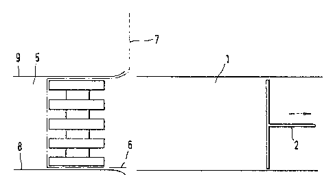
In a first compressing channel 1 shown in Figure
1, a compressed stack 3 of bags is pushed faward by a pusher
2 toward a section 4 of a web of packaging material. The
web section 4 of packaging material has a length which is
sufficient for wrapping the stack and is suspended to ex-
tend through a gan, which is defined by the first compressing
channel 1 and a succeeding second compressing channel 5,
which are closely spaced apart.
In the position shown in Figure 2. the stack 3 of
bags has been pushed into the compressing channel 5 and has
entrained the curtainlike web section 4 of packaging ma-
terial whereas the pusher 2 has been retracted over part of
its stroke. In Figure 2 the stack inserted into the second
compressing channel is covered by the web section of packag-
ing material on three side faces and tap and bottom portions
6, 7 of the web section of packaging material protrude from
the rear side face of the stack. The second compressing
channel 5 comprises a stationary bottom plate a and a rake-
like top grid, which consists of discrete parallel bars 9.
The rakelike grid has such a width that the web section 4 of
packaging material laterally protrudes from the grid 9 at
troth ends of the stack 3 so that folding elements can engage
the protruding end portions of the tubular wrapper, which
will subsequently be formed by the web section of packaging
material.
Figure 4 is a perspective view showing the stack
3 and the web section of packaging material partly covering
said stack in the same position as in Figure 2. It is also
-8-
apparent from Figure 4 that 'the bags of the stack 3 con-
stitute partial stacks, which are so offset from each other
that the handles of at least one partial stack are disposed
between the bottom portions of the bags of adjacent partial
stacks. It is also apparent farm Figure 4 that the stack
assembled form the partial stacks exerts the strongest re-
silient forces adjacent to the handles 10 because the ma-
terial which constitutes each handle is thicker than the
material of which each bag is composed. In the position
shown in Figure 4, suitable means, not shown, are used to
fold down the top portion 7 of the web section of packaging
material and to provide a row of glue dots 11 on the bottom
edge portion of the top portion 7. Thereafter, the bottom
portion 6 of the web section of packaging material is folded
upwardly and forced against the raw 11 of glue dots. As a
result, the stack is now surrounded by a tubular wrapper
formed by the web section of packaging material, as is shown
in Figure 6.
Rs is illustrated in Figure 7, a pair of folding
plates 12 are now moved against one side portion of one pro-
truding end portion of the tubular wrapper and across the
adjacent end face of the stack to impart to said protruding
end portion the shape shown in Figure 7. Two glue dots 13
and 14 are subseguently applied to the inside surface of
the portion 7 of the wrapper. Thereafter the two folding
plates 1?_ are moved apart in the directions indicated by the
arrow B in Figure 8 to the position which is shown in Fi-
gure 9. Rt this stage of the packaging operation, additional
glue dots 15 are applied to the wrapper on the narrow side
faces of the stack and the folded corner portions l6 and 17
of the wrsoper are folded down onto said glue dots 15 by
suitable means, not shown, after the folding plates of the
pair 12 have been extracted from said folded corner portions.
N~~'~l ~~
_ g _
Because the folded corner pnrtiens 16 and 17 are
folded onto and adhesively bonded to the wrapper on narrow
side faces of the stack, the resilient forces which are
exerted by the stack in the direction indicated by the arrow
C in Figure 10 cannot exert shearing farces on the adhesive~~~
joints farmed by the glue data 15. I~hen the stack 3 of bags
which has been wrapped and packaged as described is pushed
out of the second compressing channel 5. These is no longer
a risk that the wrapper which surrounds the stack can burst
under the resilient forces exerted by the compressed stack
of baAS.