Note: Descriptions are shown in the official language in which they were submitted.
~060~
HEAD LAMP DEVICE FOR AUTOMOBILES
BACKGROUND OF THE INVENTION
1. Field of the invention
This invention relates to a head lamp device for the use
in automobiles, and particularly to an improvement of a head
lamp cover thereof.
2. Brief Description of the Prior Art
Heretofore, two types of head lamp devices for
automobiles are known. One is of the type called
"stationary type device", and the other is of the type called
"retractable device". The stationary type device is always
exposed from the bonnet. The retractable device is
retracted and hidden in a bonnet when it is not in operation
and brought out when it is to be actuated.
However, the conventional stationary type head lamp
device had the shortcomings that since a front cover lens is
always exposed to the surface of the bonnet, design of the
bonnet is restricted.
On the other hand, the conventional retractable type
head lamp device had the advantages that when the head lamp
is not in operation, the surface of the bonnet looks smooth
and fancy because the head lamp is hidden in the bonnet.
However, this conventional device also had the shortcomings
- 6 ~
that when the head lamp is to be actuated, the head lamp is required to be
brought out from the inner side of the bonnet so as to be projected from the
bonnet and therefore, the vehicle gives a different impression (i.e., the
appearance of the vehicle is dedegraded). In addition, when the vehicle is
running, the wind hits the head lamp to generate a vortex (i.e., mass of
whirling wind) with the results that air resistance to the vehicle is increased.
SUMMARY OF THE INVENTION
It is therefore an object of the present invention to provide, in order to
obviate the above shortcomings, a head lamp device for automobiles, in which
the surface of the bonnet is always m~int~ined smooth whether the head lamp
is actuated or not, and the air stream of the wind is not disturbed when a
vehicle is running.
The above object has been achieved by providing a head lamp device
for automobiles comprising a light source and a cover member arranged in
front of the light source, said light source comprising a transparent hard resin
plate curved outwardly at a central part thereof, and a transparent soft resin
sheet being intimately in contact with a rear surface of said transparent hard
resin plate with a peripheral edge of said transparent soft resin sheet attached
fluid tight to a peripheral edge of said transparent hard resin plate, said
~,~.,,
20608~1
transparent hard resin plate being provided with a pipe served as a port
through which a colored solution is supplied into and removed from a space
formed between said transparent hard resin plate and said transparent soft resin
sheet.
The transparent hard resin plate and transparent soft resin sheet may be
colorless transparent.
The colored solution may be an anti-freezing solution.
The port pipe may be disposed to a lower part of the transparent hard
resin plate.
By virtue of the above-mentioned constitution of a head lamp device for
automobiles according to the present invention, when the head lamp is not in
operation, the colored solution is supplied into the space between the
transparent hard resin plate and the transparent soft resin sheet through the port
pipe. By this, the transparent soft resin sheet is swollen, and a colored
solution layer is formed between the transparent hard resin plate and the
transparent soft resin sheet. As a result, the cover member is given coloring
by the colored solution. Then, the vehicle gives an impression to those who
look the vehicle that no head lamp device is mounted on it.
On the other hand, when the head lamp is to be actuated, the colored
solution is removed from the space between the transparent hard resin plate
2060821
and the transparent soft resin sheet through the port pipe by means of actuation
of a pump. By this, the transparent soft resin sheet is caused to be intim~tely
contacted with the transparent hard resin plate so as to be integral therewith.
In the foregoing state, rays of light coming from the light source is allowed
to penetrate the cover member to illllmin~te the front of the cover member.
Accordingly, by the use of this head lamp device for automobiles, the
surface of the bonnet of a vehicle can be maintained smooth whether the head
lamp is in operation or not. Moreover, the vehicle equipped with this device
can run smoothly and stably because the air stream of the wind is not
disturbed when the vehicle is running.
If the transparent hard resin plate and transparent soft resin sheet are
designed to be colorless transparent, the same coloring as that of the vehicle
body can be easily given to the head cover member when the head lamp is not
in operation.
The above and other objects and the features and advantages of the
present invention will be more clearly understood from the following
description taken in conjunction with the accompanying drawings.
BRIEF DESCRIPTION OF THE DRAWINGS
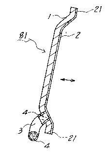
Fig. 1 is a perspective view of a head lamp device for
.,
~0608~ 1
automobiles according to one embodiment of the present
invention;
Fig. 2 is a front view thereof;
Fig. 3 is a perspective view of the device of Fig. 1,
but with a colored solution filled therein;
Fig. 4 is an enlarged sectional view taken on line IV-IV
of Fig. l;
Fig. 5 is likewise an enlarged sectional view taken on
line V-V of Fig. 3; and
Fig. 6 is a schematic view of the device mounted on a
vehicle.
DETAILED DESCRIPTION OF THE EMBODIMENT
One preferred embodiment of the present invention will
now be described with reference to the accompanying drawings.
Referring first to Fig. 6, the numeral 9 denotes a
vehicle, and 91, a bonnet thereof. A head lamp device
generally designated by the numeral 8 is embedded in a front
part of the bonnet 91. A cover member 81 of the head lamp
device 8 is flush with the surface of the bonnet 91. The
numeral 82 denotes a light source for the head lamp device 8.
Next, the cover member 81 will be described in detail
with reference to Figs. 1 through 5 inclusive.
In Figs. 1 through 3, the numeral 1 denotes a colorless
transparent hard resin plate which constitutes the cover mem-
2a60s~l
ber 81. The hard resin plate 1 is curved outwardly at acentral portion thereof. The numeral 2 denotes a colorless
transparent soft resin sheet which also constitutes the cover
member 81. The soft resin sheet 2 is in intimate contact
with the hard resin plate 1 with a peripheral edge 21 of the
former attached fluid tight to the latter. By virtue of the
foregoing arrangement, the soft resin sheet 2 can be recipro-
cally moved in directions as shown by a two-headed arrow of
Fig. 4 with respect to the hard resin plate 1, and a state of
Fig. 4 and a state of Fig. 5 can be selectively provided.
The numeral 3 denotes a pipe (which is sometimes referred to
as a port pipe~, which is mounted to the hard resin plate 1.
This pipe 3 is adapted to supply therethrough a colored anti-
freezing solution (including glycol) into a space between the
hard resin plate 1 and the soft resin sheet 2 and to remove
therethrough the solution from the space.
When a colored anti-freezing solution is supplied into
the space between the hard resin plate 1 and the soft resin
sheet 2 from a solution tank through the pipe 3 by means of
actuation of a motor (not shown), the soft resin sheet 2 is
expanded rightward by fluid pressure, to thereby form a
colored solution layer 4 between the hard resin plate 1 and
the colorless transparent soft resin sheet 2 (see Fig. 5).
Then, the cover member 81 is colored by the colored solution
4. As a result, existence of the cover member 81 and there-
206082 I
fore, the head lamp device 8 becomes difficult to be recog-
nized.
On the other handt when the colored anti-freezing solu-
tion 4 is removed from the colored solution layer 4 between
the hard resin plate 1 and the colorless transparent soft
resin sheet 2 through the pipe 3 by means of actuation of a
motor (not shown), the soft resin sheet 2 is intimately con-
tacted with the colorless transparent resin plate 1 so as to
be integral therewith (see Fig. 4). Then, rays of light
coming from the light source 82 is allowed to transmit the
cover member 81 to illuminate the front of the cover member
81.
In this embodiment, the motor pump is operatively con-
nected to a switch of the head lamp.
Although one preferred embodiment has been described,
the present invention should by no means be limited to this
embodiment. It goes without saying that various changes and
modifications can be made by those skilled in the art without
departing from the scope of the appended claim.