Note: Descriptions are shown in the official language in which they were submitted.
~oo~~s~
-1-
DRUM AND PROCESS FOR HANDLING DRUM LINERS
FIELD OF THE INVENTION
This invention relates to drums for handling
hazardous materials and liquids that are not to be exposed to
the environment. More particularly, the invention relates to
drums provided with impervious flexible removable liners and
methods for ecologically disposing of the liners.
BACKGROUND OF THE INVENTION
Drums have been used to store and transport fluids
for many years. Wooden barrels have been used for generations
to store and transport a wide variety of liquids, e.g, water,
wine, etc. Later, steel drums were developed to handle a
greater variety of liquids. Hydrocarbons and other chemical
products are typically transported in steel drums. More
recently, polyethylene drums have been developed to handle
hazardous chemical liquids.
With the increase in drum transportation of
hazardous chemical liquids, liners resistant to the
deleterious effects of hazardous chemicals have been developed
for the interior of the drums.
Rigid liners for drums as illustrated by United
States Patent No. 4, 712, 711 have been used since the 1950s for
distribution of hazardous liquids. However, they are
difficult to remove from a drum when emptied and are not
easily collapsible.
However, the toxicity and other hazardous effects of
the liquids stored and transported in drums has required
reconditioning of the drums prior to reuse. In effect, an
entire industry exists to remove all trace of the contents of
drums and safely dispose of the contents. In view of the
hazardous nature of many of the liquids found in drums, the
problem of disposing of the contents in an ecologically safe
manner has arisen.
Flexible liners such as illustrated by United States
Patent Nos. 4,635,814; 3,409,201; 3,262,628; 3,215,307 and
2~61.i~1
-2-
3,167,210 have been developed and have promise in containing
hazardous liquids to facilitate ecologically safe disposal of
the liquids.
SUMMARY OF THE INVENTION
This invention is., directed to using flexible drum
liners in a safe reliable process for disposing of the liners
without allowing the contents of the drum liners to
contaminate the environment.
A further objective of the invention is to provide
a drum with a liner adapted for safe withdrawal from the drum.
To this end, a conventional steel or polyethylene
drum is provided with a flexible liner having a fitting
hermetically secured thereto. The fitting of the flexible
drum liner is adapted to be mounted in the bung hole of the
drum. Detachment means and means to reseal the fitting are
also provided after the drum has been emptied.
The process of the invention proceeds after the drum
has been emptied by first evacuating any air and other gases
from a spent liner to collapse the liner. The liner is then
resealed by securing a reseal means (cap) to the fitting after
the liner has been collapsed. A plunger having a head
specially adapted to grip the reseal cap is attached to the
reseal cap, the liner fitting is then released from the drum
cover bung hole and the plunger is used to push the fitting
and the collapsed liner to the bottom of the drum.
Thereafter, the top of the drum is removed, usually
by a cutting operation and the flexible liner and fitting are
removed from the drum and compacted into a safe disposal drum
made of a plastic, such as polyethylene.
When a disposal drum has been filled with flexible
liners, the disposal drum i.s transported to a safe site for
ultimate disposal, usually by incineration.
201 16~
-2(a)-
In a broad aspect, the present invention relates to a process for discarding
used drum
liners, after the contents have been removed, comprising the steps o~ a)
collapsing the liner
within the drum; b) sealing the collapsed liner; c) moving the collapsed liner
to the bottom of the
drum; d) forming an access opening in the drum; e) removing the sealed,
collapsed liner from the
drum; and f) ecologically disposing of the sealed collapsed liner.
~i
2~fi~~~~
-3-
DESCRIPTION OF THE DRAWINGS
The present invention will be better understood when
considered with the accompanying drawings wherein:
FIGURE 1 is a sectional elevational view of a drum
used in the process of the invention;
FIGURE 2 is a top plan view of the drum of FIGURE 1;
FIGURE 3 is a sectional elevational view taken
through lines 3-3 of FIGURE 2;
FIGURE 4 is a partial plan view taken through line
4-4 of FIGURE 3;
FIGURE 5 is a view illustrating the evacuation of
the flexible liners within the drum;
FIGURE 6 is a view illustrating the attachment of
the plunger to the reseal cap of the flexible bag fitting;
FIGURE 7 is a view illustrating the liner fitting
with the retaining ring removed;
FIGURE 8 is a view illustrating positive release of
the fitting from the drum;
FIGURE 9 is a view illustrating removal of the drum
lid;
FIGURE 9A is a sectional view illustrating removal
of the drum lid;
FIGURE 10 is a view illustrating compaction of the
drum liners of the invention into a disposal drum; and
FIGURE 11 is an illustration of the plunger of the
process.
DESCRIPTION OF THE PREFERRED EMBODIMENT
The present invention has application in all
instances wherein drum reconditioning occurs. It applies to
all drums capable of storing hazardous liquids such as
corrosive or flammable liquids that must be safely handled to
avoid ecological harm. However, the present invention will be
described with reference to a conventional drum formed with a
non-removable top head.
261 161
-4-
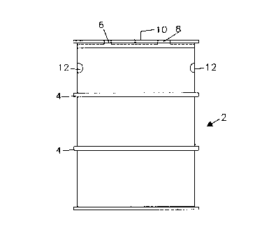
As best seen in FIGURE 1, a steel fifty-five gallon
drum (2) of conventional dimensions is shown. The drum (2) is
provided with conventional rolling hoops (4), an opening (8)
in the top head (10) and a three-quarter inch (~/,") vent (6)
with a snap-on seal. In addition, the drum (2) is provided
with a plurality of at, least three (3) essentially
symmetrically arranged indentations (12) located on the drum
body about two inches (2") below the top head (10). The
indentations ( 12 ) form internal protrusions ( 14 ) , best seen in
FIGURE 2, that extend about one half inch (~") into the
interior of the drum (2).
The drum (2) is also provided with a flexible liner
(16). The flexible liner (16) is seen in FIGURE 3 secured to
a fitting ( 18 ) that attaches to the drum bung hole ( 8 ) . A
flexible liner particularly suitable for the application is
manufactured by Scholle Corporation and is preferably single
or multiple ply of low density polyethylene and/or nylon film
of approximately 2-10 mils thickness. Most preferred at this
time is a flexible liner (16) having an inner ply of
approximately 4 mils thickness and an outer ply of
approximately 4 mils thickness. The characteristics of the
flexible liner (16) required for this process are resistance
to chemical attack and sufficient toughness to withstand the
handling associated with storage and transportation of
chemical liquids and treatment and removal of the liner for
safe disposal. It is important to the process of this
invention that rupture of the flexible lines be avoided to
insure that any fluid contained within the flexible liner (16)
be prevented from escaping into the environment.
The flexible liner (16) is conventionally welded
(heat bonded) to a fitting (18) designed to be secured to a
conventional drum bung hole (8) in the top head (10). The
opening is essentially circular with diametrically opposed
locating tabs (9). The fitting (18) best seen in FIGURES 3-7
is comprised of a large diameter flange (20), a smaller
diameter flange (22) and a threaded collar (24). The collar
-5-
(24) has an outside diameter slightly smaller than the opening
(8) and has diametrically opposed vertical slots (25) that are
sized to receive the tabs (9). The tabs (9) engage the
vertical slots (25) to prevent rotation of the fitting (18)
and thus the liner (16) within the drum (2). 'A gasket (26)
fits over the collar (24) and rests on the smaller diameter
flange (22).
The fitting (18) is secured to the drum top head
(10) by a retaining ring (28) that takes the form of a
threaded nut. The retaining ring (28) is sized to thread on
the outside threads (30) of the collar and is torqued against
the drum top head (10) to force the gasket (26) against the
inside surface of the drum top head (10). The smaller
diameter flange (22) provides the bearing surface for the
gasket (26) and thereby prevents the flexible liner section
. welded to the larger diameter flange (20) from being
compressed against the inside surface of the drum top head
(10). Practice has shown that a fitting (18) with a collar
(24) having an outside diameter of 2.9 inches (74mm), a large
diameter flange ( 20 ) of 4 . 6 inches ( 117mm) diameter and . 04
inches (lm) thickness, and a smaller diameter flange (22), of
3.2 inches (81mm) diameter and .08 inches (2mm) thickness
provide a fitting (18) that can be safely secured to a drum
top head (10) without subjecting the flexible liner (16) to
compressive forces from the inside surface of the drum top
head (10) that might cause abrasion or wear. The entire
fitting (18) is formed of polyethylene.
The disposal process of the present invention
proceeds after the contents of the drum (2) have been removed.
If the vent (6) has not been opened during discharge of the
contents of the drum (2), it must be opened during the
disposal procedure. A vacuum pump (34) seen in FIGURE 5, is
connected to the fitting ( 18 ) by a hose ( 36 ) in which a filter
(38) of activated carbon is removably inserted. The vacuum
pump (34) is run at only a slight vacuum designed only to
collapse the flexible liner (16). In practice, a vacuum of
20~~~~~
-6-
about 1.0 to 1.5 psig less than atmospheric is sufficient to
collapse the liner bag (16).
After collapse of the liner ( 16 ) , a reseal plug ( 40 )
is threaded into the interior threads (32) of the collar (24)
of the fitting (18). A conventional TRI-SURE reseal plug is
well suited for the application. As seen in FIGURE 6, the
reseal plug (40) has an essentially circular recess (42) in
the upper surface and an essentially circular wall (50) above
the recess (42) interrupted only by inward projecting lugs
(53) best seen in FIGURE 11. After the reseal plug (40) has
been secured to the fitting (18), a plunger (44) is attached
to the reseal plug (40). The plunger (44) best seen in FIGURE
11 is a cylindrical member having a handle (46) and an array
of resiliently mounted fingers (48) that can be spread to form
a force fit with the circular wall (50) when the fingers (48)
are expanded. The plunger (44) is provided with an interior
sliding cylinder (49) that can be depressed to force the
resilient fingers (48) outwardly or elevated to release the
force on the fingers (48).
A catch comprised of a depending lip (52) on the
handle (46) and an upwardly extending lip (54) on the plunger
body (44) retains the centrally disposed cylinder (49) in a
position to force the resiliently mounted fingers (48) against
the circular wall (50) of the plug (40) when the handle (46)
is rotated to effect engagement of the lips (52) and (54).
With the plunger ( 44 ) attached to the reseal plug
(40), the retaining ring (28) is removed from the collar (24)
and the plunger (44) is used to positively push the fitting
(18) and flexible liner (16) to the bottom of the drum (2).
A standard drum head remover (51), as seen in
FIGURES 9 and 9A, is then attached to the chime (41) of the
drum (2) and engaged to. cut the lid (10) from the drum (2).
A conventional lid or cover remover (51) is used such as a
WIZARD~ drum deheader which is comprised of a motor (55),
rollers (57) and a cutting blade (59). The protrusions (14)
serve to prevent the top head (10) from falling to the bottom
20~ 1 161
of the drum (2) and possibly damaging the liner (16) after the
drum top head (10) has been completely cut from drum (2).
The composite of liner (16) and fitting (18) with
the reseal plug or cap (40) is then placed in the disposal
drum (60). Compaction of the used liners (16) ~is employed to
enable a large quantity of, liners (16) to fit within the
disposal drum (60). The disposal drum (60) is formed of
polyethylene material that is chemically similar to that used
in the liners (16) and is typically a thirty to fifty-seven
gallon capacity Act Open Head Drum manufactured by Russell-
Stanley Corporation. Compaction, as seen in FIGURE 10, can be
provided by a compactor (62) having a plunger (64) on which a
circular plate (66) is formed. The lower surface (68) of the
plate ( 66 ) is coated with polytetraflouroethylene or a similar
abhesive material to avoid abrading the liners (16) during
compaction. It has been found that evacuated liners (16) can
be compacted to a density of four to eight pounds per cu. ft.
with a compaction force of about five pounds per square inch
without damaging the liners (16).
The disposal drum (60) is transported to an
incineration site wherein the drum (60) and liners (16),
complete with fittings (18) and reseal plugs (40), are
incinerated.
Many obvious variations will suggest themselves to
those skilled in the art in light of the above description.
All such obvious variations are within the full intended scope
of the invention, limited only by the appended claims.