Note: Descriptions are shown in the official language in which they were submitted.
CA 02061229 2003-O1-29
-1-
OSTOMY APPLIANCE
FIELD OF THE INVENTION
The present invention relates to an ostomy appliance which is easily securable
to an
aperature or opening formed on the surface of a human body, the appliance
being usable for
S such purposes as receiving and collecting waste products expelled from the
inside of the
human body and also for introducing a liquid preparation into the human body.
BACKGROUND OF THE INVENTION
So-called ostomy appliances are generally furnished for receiving and holding
various
waste products and waste liquids discharged from the human body and such
appliances are
sometimes used for introducing a liquid preparation into the human body for
therapy or washing
at an aperture or opening formed on or through the surface of the human body
such as the
fistula formed on the surface of the body by performing surgical operations
wherein such
devices are used to combat rectal or bladder disease. Other applications
include use in
connection with a leading enteric canal, a ureter tube or other tube connected
to the body
surface or opening formed on the surface of the human body by a wound.
Artificial anal
appliances and artificial urinary bladder appliances are typical examples.
Since ostomy
appliances are to treat waste products discharged from the human body, it is
necessary to
perform such removal sanitarily without contacting such waste products with
the skin or the
opening while at the same time maintaining the sanitary reliability of the
device such that such
waste products do not leak out during use. It is also important that such
appliances be easy to
put on and to take off and that they are comfortable to the skin since such
devices are secured
directly to the skin surface.
Various ostomy appliances have heretofore been devised and broadly employed
for use
in attempting to satisfy the above-described objects and requirements
including an ostomy
appliance proposed by the present applicant (Japanese Utility Model
Application No. (Hei) 2-
CA 02061229 2003-O1-29
-2-
59606). Such previous ostomy appliances comprise an adhesive plate member
having an
aperture or opening extending therethrough and adhesive material on one side
thereof around
the aperture or opening enabling the adhesive plate member to be fixed by
adhesion around
an aperature or opening of a human body. The adhesive plate member includes a
first flange
extending around the aperture therethrough on the non-adhesive side of the
member. A second
member has a second flange capable of detachably fitting to the first flange
on the adhesive
plate member, which second flange has an aperture or opening extending
therethrough which
communicates with a pouch or bag attached to the second flange, which pouch or
bag receives
waste products discharged through the aperture in the human body. The first
and second
flanges respectively include fitting means such as, for instance, a prominence
and a groove
which are annular or ring-shape and are cooperatively engageable for
attachment of the second
or bag member to the first or adhesive plate member.
When the waste products are accumulated in the bag or pouch, the second flange
can
1 ~ be disengaged from the first flange to remove the pouch or bag member from
the adhesive
plate member on the human body. The waste products can then be removed from
the bag and
the bag either washed for re-use, or alternatively, replaced with a totally
new second member.
The pouch or bag member can also alternatively be replaced by a cap-type or
other type
member, as desired.
In such known ostomy appliances, the first flange and the second flange are
joined by
pressing together the respective fitting means. To avoid pressing against the
skin of the wearer
when attaching the second member to the first member, it is desirable to
construct such ostomy
appliances such that a finger can be inserted between the first flange and the
adhesive plate
so as to be able to sufficiently support and provide backing for the first
flange during
attachment. To this end, the outer diameter of the first flange is made
relatively large.
Such known devices have several shortcomings which limit their desirableness
and
usefulness as effective, sanitary, comfortable and easy to use appliances. For
example, when
attempting to position the respective flanges of the known ostomy appliances
for engagement
or attachment thereof, it is difficult for the user or patient to directly
visually confirm the relative
positions of the flanges, and thus the patient has to gropingly or by feel
position the flanges in
many cases. Additionally, as the opening or aperture on the human body is
often located on the
CA 02061229 2003-O1-29
-3-
lower half of the body, positioning of the relative flanges can be made
further difficult.
SUMMARY OF THE INVENTION
S
The ostomy appliance according to the present invention comprises a first
member
having an adhesive plate (skin-contacting plate) fixable by adhesion around
the aperture or
opening of a human body. A first flange is attached to the adhesive plate
member and is
located adjacent to the non-adhesive side thereof, and a second member
including a second
flange capable of fitting or cooperatively engaging the first flange can be
detachably fitted to
the first member. The adhesive plate has an aperture or opening which
corresponds to the
aperture or opening of the human body. The first flange is attached or joined
to the adhesive
plate member directly or through a member having an annular shape such as a
washer made
of soft plastic and which flange extends outwardly or radially from the
aperture in the adhesive
1 S plate nearly adjacent to and along the surface of the adhesive plate. On
the side of the first
flange opposite the adhesive plate, fitting means such as a ring-form or
annular fitting portion
are provided. Adjacent the outer periphery or peripheral edge of the fitting
means is located a
collar or tab. The collar or tab includes means for aligning the first and
second flanges, which
alignment means can comprise one or more cut-away recesses or notches or
truncated
portions formed in the collar or tab, the recess or notch or truncated portion
extending inwardly
to adjacent the outermost periphery of the fitting portion and being of such a
size as to allow
the insertion of a finger thereinto. The second flange also includes
corresponding fitting means
such as a ring-form or annular fitting portion on one side thereof dimensioned
to fit or
cooperatively engage the fitting portion of the first flange, and a pouch or
bag or cap on the
2S opposite side thereof.
When the first and second fitting means are to be fitted or coupled together,
a finger can
be inserted into the notch of the collar and located adjacent the outer
periphery of the first
flange, whereby the position of the fitting portion of the first flange member
is clearly perceived.
The second flange can then be located, by feel, in alignment with the first
flange and guided
into cooperative engagement with the first flange. Furthermore, by inserting
one or more fingers
between the collar or tab of the first flange and the adhesive plate, the
fitting portions of both
flanges can be pressed together, the first flange being supported with the
fingers. The second
flange can be detached from the first flange by grasping the collar of the
first flange and the
CA 02061229 2003-O1-29
-4-
second flange with the fingers and pulling the flanges apart in the
conventional manner without
allowing the pulling force to act on the adhesive plate.
It is therefore a principal object of the present invention to provide means
facilitating the
alignment and fitting together of the respective members of an ostomy
appliance.
Another object is to provide an ostomy appliance having means enabling the
attachment
of an ostomy bag to an adhesive plate adhered to a patient by feel alone.
Another object is to provide an ostomy appliance wherein a single finger can
be used
for aligning and guiding the respective first and second members of the ostomy
appliance into
engagement with each other.
BRIEF DESCRIPTtON OF THE DRAWINGS
FIGS.1 (a) and 1 (b) are each front elevational views showing first and second
members,
respectively, of an ostomy appliance constructed according to the teachings of
the present
invention;
FIG. 2 is a cross-sectional view of the first and second members of the ostomy
appliance of FIG. 1 shown in alignment for being joined together;
FIG. 3 is a front elevational view of the first member of the ostomy appliance
of FIG. 1,
showing an alternative flange construction therefor; and
FIG. 4 is a perspective view of the ostomy appliance of FIG. 1, illustrating
how the
respective first and second members thereof can be held by a user to be joined
together.
DETAILED DESCRIPTION OF THE PREFERRED EMBODIMENTS
CA 02061229 2003-O1-29
-5-
Practical embodiment of the present device will now be described hereinbelow
with
reference to the drawings.
Referring to the drawings more particularly by reference numbers wherein like
numerals
refer to like parts, numeral 1 in FIG. 1 (a) denotes a first or adhesive plate
member comprising
an adhesive plate for attaching to the skin of a patient, which member is
shown for instance as
being square in shape, and has an opening or aperture 2 positioned in
approximately the center
thereof. Referring briefly to FIG. 2, the adhesive plate member 1 includes an
adhesive layer 3
on a side thereof designated as the adhesive side. Numeral 4 denotes a first
flange portion of
the first member, which first flange portion 4 is preferably concentrically
positioned with respect
to the opening 2 on the adhesive plate by means of an annular inner periphery
5 which is fixedly
or otherwise attached to the adhesive plate, for example, by welding the inner
periphery 5 to
the surface of the non-adhesive side of the adhesive plate. The first flange 4
extends radially
outwardly from the annular inner periphery 5 adjacent to and nearly along the
non-adhesive
side 6 of the adhesive plate. Fitting means such as an annular or ring-form
fitting portion 7 are
provided on the side of the first flange 4 opposite the non-adhesive side 6 of
the adhesive plate.
A collar or tab 8 comprises the radially outermost portion of the first flange
4, which collar or tab
8 is located outwardly of the fitting portion 7. The fitting portion 7 can
consist of any suitable
fitting means, such as a pair of annular or ring-form projections or
prominences 9. The collar
or tab 8 can include any desired number of cut-away recesses, notches or
truncated portions,
such as shown at 10 and 11, formed for instance by linearly cutting away
opposing portions of
the collar or tab 8 in such a manner that the cut-away recesses or truncated
portions 10 and
11 reach or extend inwardly to the outermost periphery 12 of the fitting
portion 7. The external
diameter d<sub>1</sub> of the fitting portion 7, as measured between opposing
portions of the
outermost peripheral edge 12 of the fitting portion 7 is purposefully smaller
than the external
diameter d<sub>2</sub> of the first flange 4, as measured between opposite outermost
peripheral edge
portions of the collar or tab 8.
Numeral 13 denotes a second flange, which second flange 13 includes fitting
means
such as an annular or ring-form fitting portion 14 on one side thereof, as
shown in FIG. 1 (b) and
in FIG. 2. A tab 15 extends radially outwardly from the annular or ring-form
fitting portion 14.
A pouch or bag 16 is attached to the second flange 13 on the side thereof
opposite the annular
or ring-form fitting portion 14. The fitting portion 14 is cooperatively
engageable with the fitting
portion 7 of the first member 1, for instance including a pair of annular
grooves 17 into which
CA 02061229 2003-O1-29
-6-
the projections 9 of the fitting portion 7 are cooperatively insertable.
FIG. 3 shows an alternative embodiment of the first or adhesive plate member 1
in which
the portions thereof corresponding to the portions of the embodiment shown in
FIG. 1 (a) and
FIG. 2 are referenced by the same numerals. This embodiment differs from the
embodiment
shown in FIG. 1 (a) and FIG. 2 in that in the embodiment shown in FIG. 3, the
adhesive plate
member 1 is round in shape, and includes only one cut-away recess or notch 10,
which notch
is curved or generally U-shaped in construction and extends to the outermost
periphery 12
of the fitting portion 7.
As for the construction of the adhesive plate member 1, this member can be
composed
of any one of numerous conventional constructions which have hitherto been
used, such as for
instance, a plate consisting of a skin protective agent which is composed of a
hydrophillic
polymer and a hydrophobic viscous polymer and having an adhesive or sticky
foam sheet or
film thereon, or a plate having viscous reinforcing tape on a outer periphery
thereof, a plate
obtained by coating adhesive on a foam sheet or film, or a plate having on the
surface thereof,
a film such as a polyethylene, ethylene-vinyl acetate copolymer, ethylene-
ethyl acrylate
copolymer, ethylene-ethyl acrylate copolymer polypropylene, polyvinyl
chloride, polyester,
polyamide or the like, or a film on the surface thereof obtained by laminating
appropriately the
above-identified films may likewise be used.
As for the material used in the construction of the first flange, an ethylene-
ethyl acrylate
copolymer, ethylene-vinyl acetate copolymer, ethylene-ethyl acrylate
copolymer, ethylene-
methyl methacrylate copolymer, polyethylene, vinyl chloride, ethylene-acrylic
acid copolymer,
ethylene-methacrylic acid copolymer, polyethylene chloride or the like may be
used. The
thickness of the coupled or adhered portion (of the first flange member) is,
preferably, not more
than about 1 mm. For adhering or fixing the first flange to the adhesive
plate, a variety of
conventionally known means may be utilized such as a method of welding using
heat, a method
of welding a film forming part of the adhesive plate to the first flange using
a high frequency
welder or supersonic welder and a method of adhering or sticking the film to
the adhesive plate,
using adhesives, and the like.
CA 02061229 2003-O1-29
The same material used in the construction of the first flange 4 may also be
used for
construction of the second flange 13. The bag 16 may be fixed to the second
flange by means
of thermal welding, high frequency welding, supersonic welding, or by adhesion
with adhesives
or the like.
As the fitting portions of the first and second flanges, not only the
combination of
projections and grooves as shown may be used, but also various other fitting
structures can be
utilized. Moreover, the shape of the fitting portions is not necessarily
round, as shown, but
alternatively can be of elliptical or other shape, as desired. Furthermore, a
cap member, stopper
member or the like may be set or used in place of the pouch or bag 16.
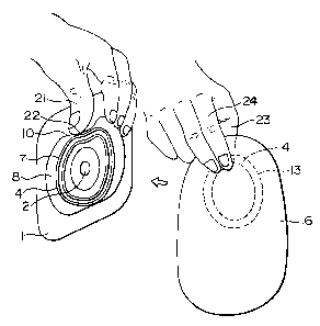
Operation and use of the present ostomy appliance will now be explained with
reference
to FIG. 4
The adhesive plate 1 is adhered to a patient's skin so that the opening 2
thereof
overlays or is superimposed on the desired aperture, for example, a stoma. The
collar portion
8 of the first flange 4 can then be raised or lifted away from the non-
adhesive side 6 of the
adhesive plate, for instance using the thumb 21 of a first hand, wherein the
belly of the thumb
21 touches a portion 22 of the notch 10 of the collar 8 which portion 22 is
the closest possible
to the fitting portion 7. The fitting portion 14 of the second flange 13 is
pinched by and between
fingers, such as for instance, the thumb 23 and the forefinger 24 of the other
hand and then the
thumb 23 is brought into contact with the thumb 21 on the first flange side,
whereby the two
fitting portions 7 and 14 are brought to the correctly aligned and opposed
positions. The fingers
of the first hand are then slid between the collar 8 and the adhesive plate 1,
and the two fitting
portions are pinched or pressed together successively therealong. In this way,
the two fitting
portions are fitted to each other without any pressing force acting on the
patient's skin or the
stoma.
The second flange is detached as follows: the collar portion 8 of the first
flange 4 is
supported by pinching it with the fingers or pressing it towards the adhesive
plate side, while
the second flange 13 is pulled by holding the tab 15 thereof with the fingers,
whereby the
second flange 13 can be easily detached without allowing any pulling force to
act on the
CA 02061229 2003-O1-29
_8_
patient's skin or the stoma, or against the adhered portions of the adhesive
plate and the first
flange.
According to the present invention, the cut-away recess or notch provided in
the collar
portion associated with the first flange is utilized so as to ensure that the
positional registration
between the fitting portion of the first flange and the fitting portion of the
second flange can be
made easily yet accurately; the collar portion is utilized so as to ensure
that the fitting or
engagement between the two fitting portions can be effected without causing
any pressing force
to act on the human body; and, through the collar portion, it is made possible
to ensure that the
two fitting portions can be separated from each other without causing any
pulling force to act
on the human body and the mutually adhered portions of the adhesive plate and
the first flange.
Thus, the operation of mounting and demounting the ostomy appliance can be
very easily
carried out without giving pain to the patient.