Note: Descriptions are shown in the official language in which they were submitted.
~3~
CAP OF WRITING INSTRUMENT AND THE LIKE
BACKGROUND OF THE INVENTION
Field of the invention
The present invention relates to an improved cap put
on the front end of writing instruments such as a sign pen,
marker, aqueous ball pen and the like to prevent evaporation of
the ink contained therein.
Prior Art
Conventional caps used for a sign pen, marker and the
like are formed of resin materials excellent in ink evaporation
suppressibility, an~ are put on the front end of the writing
instrument, with the front end tightly inserted in an inner
hole of the cap or an inner cap provided on the inner hole.
With the conventional caps used for the sign pen,
marker and the like, it is possible such accident to occur
although very rarely depending upon the size and shape thereof
that, since the inner hole is in a blocked condition except for
the inserting side, any little child swallows the cap by
mistake which in turn clogs the throat thereby resulting in
asphyxiation.
SUMMARY OF THE INVENTION
An object of the present invention is to avoid the
risks of asphyxiation and the like in such circumference as
above by making the ventilation possible even if any little
child swallows the cap by mistake which in turn clogs the
throat and to prevent the hand or clothing of the user from
being stained by ink which spouts out from the writing tip and
an air hole provided about the writing tip (so-called pumping
.
. .
. . . .
.
2~
phenomenon), with the inner pressure within the cap reduced or
elevated when the cap is taken out or put thereon. The cap for
writing instruments according to the present invention
contrived in order to achieve the above object comprises an
inner cap with a sealing member made of an elastomer inserted
therein, a spring loaded to energize the inner cap to be
axially movable, plural ribs formed on one portion of the cap
and on other portion of the inner cap respectively to provide
suitable gaps therebetween, and a hole formed on the rear end
of the cap, said gaps and the rear end hole providing an air
passage communicating the inner hole of the cap with open air.
When a writing body is inserted in the cap, the front end of
the writing body is closely inserted in the sealing member with
the inner cap axially moved and thus there can be prevented the
getting dry of the writing tip and the evaporation of ink.
With the inner cap axially moved following the putting on or
taking out of the cap, any pressurization and depressurization
within the cap and sealing member can be prevented and thus
there can be prevented the hand or clothing of the user from
being stained by ink otherwise spouts out.
BRIEF DESCRIPTION OF THE DRAWINGS
Fig. 1 is a perspective view of a writing instrument
to which an embodiment of the present invention is applied;
Fig. 2 is a perspective view showing a condition
where a cap is taken out of a writing body;
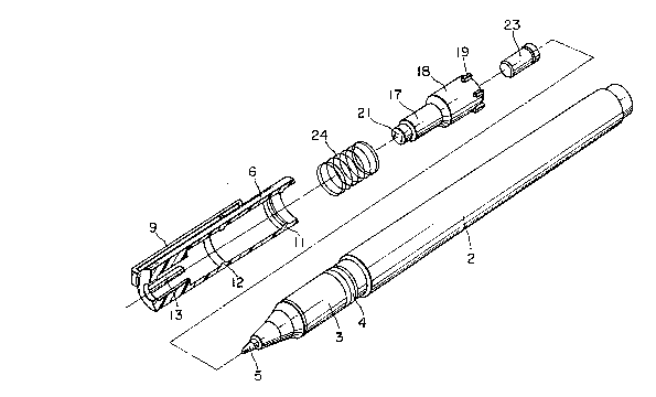
Fig. 3 is a perspective view showing the writing body
and the cap exploded and shown partly in vertical section;
Fig. 4 shows a half sectional view of the cap in a
- 2 -
.
.
'
condition where the writing body is completely inserted
thereinto;
Fig. 5 is a cross-section taken along line V - V in
Fig. 4;
Fig. 6 is a cross-section taken along line VI VI in
Fig. 4; and
Fig. 7 is a half cross-sectional view of the cap
portion in a condition directly before the writing body is
inserted thereinto.
DETAILED DESCRIPTION
Referring now to the accompanying drawings showing an
embodiment, the present invention will be described futher in
detail. The present invention is designed, in a cap of a sign
pen, marker, aqueous ball pen, etc., put on the writing front
tip thereof to prevent evaporation of ink therefrom, such that,
even if accidentally swallowed in by a little child, it does
not asphyxiate the child thanks to an air passage provided .
therein and fllrther that ink does not spout out from the
writing tip or an air hole thereabout under pressurization or
depressurization in the case of the insertion or removal of the
writing body in or from the cap to stain the hand or clothing
of a user. As shown in Figs. 3 - 7, plural ribs 13 are
provided at suitable places on the rear end side wall of an
inner hole 10 of a cap 6. Through the rear end wall with a
rear surface 15 of the cap 6, an opening 8 is formed leaving a
stepped portion 14. On the inner face of the cap 6 are formed
first and second annular engaging protrusions 11, 12. There is
housed in the cap a bottomed tubular inner cap 18 whose rear
~: :
- 3
. -
: :
,
~:
.: : . .~
~ .
2~
end is closed to form a ceiling portion 21~ The inner cap 18
has a front end hole in which a bottomed sealing member 23
airtightly formed of an elastomer is inserted and a plurality
of ribs 19 are formed at suitable places on the front end outer
periphery thereof. The inner cap 18 is inserted in the inner
hole 10 of the above cap with a compression spring 24 energing
between the front end step portions 16 of the above ribs and
the rear end step portions 20 of the ribs 19 so that the front
end of the inner cap 18 may be elastically engaged with the
engaging portion 12 provided on the inner hole 10 of the cap to
prevent the writing body 2 from moving toward the inserting
side while allowing the inner cap 18 to move rearward relative
to the cap 8. There are formed plural gaps 17 and 22
respectively between the outer periphery of the inner cap 18
and the ribs 13 of the inner hole 10 and between the inner hole
10 and the ribs 18 of the inner cap 18 to provide an air
passage between the rear end opening 8 of the cap and the inner
hole 10 for communicating with the open air.
While, at front portion on a shaft 3 of the writing
body 2 is formed an annular engaging protrusion 4 and on the
front end of the shaft 3 is provided a writing tip 5 of an
aqueous ball pen or the like. In the writing body 2 is
contained a liquid ink, while, between the interior therof an~
the writing tip is provided a control device (not shown) for
properly adjusting the outflow of ink and for reserving ink
depending on change of the inner pressure in the ink reservoir.
Location of the annular engaging protrusion 11 of the cap is
such arranged that, when it catches the annular engaging
- 4 -
.
' , . :
3~3
protrusion 4 of the shaft 3 with the writing body 2 inserted
into the inner hole 10 of the cap, the inner cap 18 retreats by
a distance S as shown in Fig. 4 with the front portion of the
shaft 3 pressing the rear end wall of the sealing member 23 and
at that time the ceiling 21 of the inner cap 18 virtually evens
with the rear end outer surface of the cap.
(Function)
The present invention is designed as above and, in a
condition where the writing body 2 is fully inserted in the cap
as shown in Fig 4, the front poriton of the writing body is
closely inserted in the sealing member 23 with the writing tip
5 pressed onto the rear end wall of the sealing member 23.
Accordingly, there can be prevented both the getting dry of the
writing tip and the evaporation of ink from the air hole
provided thereabout. Futher, since the insertion is carried
out with the inner cap 18 simultaneously retreating, the
interiors of the cap and the sealing member are not
pressuriged. While, when the writing body 2 is removed from
the cap 6, the inner cap 18 is returned inward by the returning
force of the spring 34 while following the writing body 2, and
thus there does not take place any depressurization.
Accordingly, no ink spouts out from the writing tip and the air
hole. Further, since an air passage is formed which
communicates the inner hole 10 with the opening 8 in the
condition where the writing body 2 is removed from the cap 6,
there can be prevented accidents such as asphyxiation and the
like even if the cap is swallowed by mistake to clog the
throat.
- 5 -
' ~ '
~, .: , .
Z~
(Effect of the invention)
Since the construciton and the function of the
present invention is described above, even i~ any little child
swallows the cap by mistake to clog the throat, there can be
avoided accidents such as aasphyxiation and the like, with open
air allowed to pass the interior of the cap which has an air
passage provided between the rear end opening and the cap's
inner hole. Further, the above construction provides no
inferiority in apprearence. Moreover, since there is not
caused any pressurization or depressurization in the interior
of the cap and the front portion of the writing body, there can
be prevented such problem that ink sports out from the writing
tip or the air hole to stain the hand and the clothing of the
user.
.
.
- 6 - ~
.
,
,