Language selection

Search

Patent 2062040 Summary

Third-party information liability

Some of the information on this Web page has been provided by external sources. The Government of Canada is not responsible for the accuracy, reliability or currency of the information supplied by external sources. Users wishing to rely upon this information should consult directly with the source of the information. Content provided by external sources is not subject to official languages, privacy and accessibility requirements.

Claims and Abstract availability

Any discrepancies in the text and image of the Claims and Abstract are due to differing posting times. Text of the Claims and Abstract are posted:

  • At the time the application is open to public inspection;
  • At the time of issue of the patent (grant).
(12) Patent: (11) CA 2062040
(54) English Title: MOBILE WIRELESS COMMUNICATIONS SYSTEM
(54) French Title: SYSTEME DE COMMUNICATION MOBILE SANS FIL
Status: Expired and beyond the Period of Reversal
Bibliographic Data
(51) International Patent Classification (IPC):
  • H04B 07/26 (2006.01)
  • H04W 36/08 (2009.01)
(72) Inventors :
  • PINARD, DEBORAH (Canada)
(73) Owners :
  • MITEL NETWORKS CORPORATION
(71) Applicants :
  • MITEL NETWORKS CORPORATION (Canada)
(74) Agent: MARKS & CLERK
(74) Associate agent:
(45) Issued: 2001-01-16
(22) Filed Date: 1992-02-28
(41) Open to Public Inspection: 1993-08-29
Examination requested: 1997-08-07
Availability of licence: N/A
Dedicated to the Public: N/A
(25) Language of filing: English

Patent Cooperation Treaty (PCT): No

(30) Application Priority Data: None

Abstracts

English Abstract


A mobile wireless communications system, comprises a
plurality of base stations with associated respective
coverage zones, each base station being connected to a
central host computer and being capable of establishing
two-way communication with mobile units in its associated
coverage zone and a switch having a plurality of line
interfaces connected to the base station. The host computer
can select one of the base stations in range of an active
mobile unit to establish a call therewith, determine the
line interface associated with the call, determine when a
hand off from one base station to the next is to occur as
the active mobile unit moves between coverage zones, send a
hand off message to the switch identifying the current
active line interface and the target line interface after
hand off associated with the call, and initiate a hand off
by sending a call originate message to the next base station
instructing it to originate the call on the target line
interface, The switch comprises a first memory for storing
call data records containing channel assignment and line
interface data for each call, a second memory for storing
data received from the host computer identifying the target
line interface with an imminent hand off from the active
line interface associated with the call, and an arrangement
for assigning a channel associated with the active line
interface to the target line interface on receipt of a call
origination signal on the target line interface. In this
way, a hand off can take place simply by writing the new
line interface data into the existing call data record.


Claims

Note: Claims are shown in the official language in which they were submitted.

THE EMBODIMENTS OF THE INVENTION IN WHICH AN EXCLUSIVE
PROPERTY OR PRIVILEGE IS CLAIMED ARE DEFINED AS FOLLOWS:
1. A mobile wireless communications system, comprising
a plurality of base stations with associated respective
coverage zones, each base station being connected to a
central host computer and being capable of establishing
two-way communication with mobile units in its associated
coverage zone, and a switch having a plurality of line
interfaces connected to said base station; said host
computer comprising means for selecting one of said base
stations in range of an active mobile unit to establish a
call therewith, means for determining the line interface
associated with the call, means for determining when a hand
off from one base station to the next is to occur as the
active mobile unit moves between coverage zones, means for
sending a hand off message to said switch identifying the
current active line interface and the target line interface
after hand off associated with the call, and means for
initiating hand off by sending a call originate message to
the next base station instructing it to originate the call
on the target line interface; and said switch comprising
first memory means for storing call data records containing
channel assignment and line interface data for each call,
second memory means for storing data received from the host
computer identifying the target line interface with an
imminent hand off from the active line interface associated
with the call, and means for assigning a channel associated
with the active line interface to the target line interface
on receipt of a call origination signal on the target line
interface.
2. A mobile wireless communications system as claimed
in Claim 1, wherein on receipt of the call origination
signal on the target line interface the active line
interface data in the channel data record associated with
the call is overwritten with the target line interface data.

3. A mobile wireless communications system as claimed
in Claim 1, wherein said first memory means comprises
dynamic hardware registers.
4. A mobile wireless communications system as claimed
in Claim 1, wherein said switch comprises a switching
circuit for establishing connections between designated
channels; a peripheral controller containing said line
interfaces; and a main controller comprising said first and
second memory means, a further memory means defining a
channel map, and means for sending messages to and receiving
messages from said switching circuit and said peripheral
unit to control the operation thereof.
5. A mobile wireless communications system as claimed
in Claim 1, wherein said host computer is connected to said
switch over an HCI link.

Description

Note: Descriptions are shown in the official language in which they were submitted.


2Q~2~~0
This invention relates to a mobile wireless
communications system.
Cellular technology has now become established as the
preferred method of providing a multi-user two-way wireless
communications system. In a cellular system, a coverage
area is divided into a plurality of zones or cells, each
associated with its own base station of relatively low
power. These zones are designed to be contiguous so that a
mobile unit will always be within range of at least one base
station in the coverage area. As the mobile area moves
between cells, a central computer switches base stations in
accordance with signal strength.
In a conventional cellular system, the switching from
one base station to the next or "hand off", is accomplished
using conference circuitry. This results in a complex
architecture because new called data records and channel
assignments have to be established at hand off.
According to the present invention there provided a
mobile wireless communications system, comprising a
plurality of base stations with associated respective
coverage zones, each base station being connected to a
central host computer and being capable of establishing twa-
way communication with mobile units in its associated
coverage zone, and a switch having a plurality of line
interfaces connected to said base station; said host
computer comprising means for selecting one of said base
stations in range of an active mobile unit to establish a
call therewith, means for determining the line interface
associated with the call, means for determining when a hand
off from one base station to the next is to occur as the
active mobile unit moves between coverage zones, means for
sending a hand off message to said switch identifying the
current active line interface and the target line interface
after hand off .associated with the call, and means for
- 1 -

initiating hand off by sending a call originate message to
the next base station instructing it to originate the call
on the target line interface; and said switch comprising
first memory means for storing call data records containing
channel assignment and line interface data for each call,
second memory means for storing data received from the host
computer identifying the target line interface with an
imminent hand off from the active line interface associated
with the call, and means for assigning a channel associated
with the active line interface to the target line interface
on receipt of a call origination signal on the target line
interface.
By storing the line interface data in the switch prior
to hand off all that is necessary on receipt of a call
i5 origination signal on the target interface is for the switch
to check the hand off register and find the call data record
for the current line interface. The switch can then release
the current line interface and overwrite the call data
record with the target line interface information. There is
no need to create a new call data record associated with the
new line interface circuit.
The first memory means are preferably dynamic hardware
registers.
The invention will now be described in more detail, by
way of example only, with reference to the accompanying
drawings, in which:-
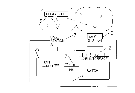
Figure 1 is block diagram of a mobile wireless
communications system in accordance with the invention; and
Figure 2 is a more detailed black diagram of the switch
forming part of the system shown in figure 1.
Referring now to Figure 1, the mobile wireless

2D~2~~0
communication system comprises a switch 1 connected through
a plurality of line interfaces 2 to a plurality of base
stations 3. Each base station 3 can be connected to any of
the line interfaces 2, but in Figure 1 base station A is
shown connected to line interface a and base station B
connected to line interface b.
Each base station 3 is associated with a coverage zone
of cell 4 and is capable of establishing two-way wireless
communication with mobile units 5 in its associated zone 4.
The base stations 3 are also connected to a host
computer 6, which is connected through an HCI link 7 to the
switch 1. The host computer 6 controls the operation of the
system.
The switch 1 is shown in more detail in Figure 2. It
comprises a peripheral controller 8 containing the line
interfaces 2, a circuit switch circuit 9, and a main
controller 10 which includes the hand off register 11, the
call data record registers 12, and the channel map 13. The
call data record registers 12 are dynamic hardware
registers. When a call is originated a call data record is
established in a register 12. This stores information
pertaining to the line interface unit and channel
assignments in the circuit switch 9.
The switch preferably employs the architecture of Mitel
GX 5000 switch. The line interface units are managed by the
peripheral controller 8, and the switch path connections, or
channels, are connected using the circuit switch 9. The
main controller 14 handles all the call processing and
communicates with the peripheral and circuit switch using
messages as shown. When the line circuit 2 originates a
call, the peripheral controller 8 sends a message to the
main controller 14, which creates the call data record, sets
up the channels, and sends a positive acknowledged signal ~'.o
- 3 -

2~~2~~0
the peripheral unit 8. The peripheral unit 8 then connects
the channels to the circuit switch from the line interface
2.
In operation, the system operates as follows:
When a call is first originated, for example by mobile
unit 5, the host computer 6 determines which base station 3
is receiving the strongest signal and designates that base
station to establish the call. The host computer 6
identifies a free line interface 2 in the switch 1 and sends ,,
l0 a message to the designated base station 3 to originate a
call to that line interface. The destination digits are
buffered by the peripheral 8 and sent to the main controller
14, which translates the digits into a destination address
and sends the message to the destination circuit via the
peripheral unit 8 to cease the destination line interface
unit. Included in this message are channels that connect up
to the circuit switch~9. When the destination line
interface has been successfully ceased, a positive
acknowledge signal is sent to the main controller. When the
terminating unit answers the call, the main controller is
informed with a message, and the originating device channels
are connected to the terminating device channels.
After call origination, channel assignments are
established in accordance with the call routing requirements
and recorded in a call data record stored in register 12
along with the identification of the active line interface.
Main controller 14 of the switch 1 sends message to the
circuit switch to set up circuits in accordance with the
required channel assignments stored in the associated call
data record. In this architecture, the call records are
merely required to have pointers to each other in order to
set up the calls.
- 4 -

2~v2~~a
During progress of the call, the host computer 6
monitors signal strength, and as the mobile unit 5 moves
into an adjacent zone 4 determines that a hand off is about
to take place. When this occurs, the host computer 6 sends
an HCI message to the switch 1 informing it of the imminent
hand off. Included in the message is data identifying the
active line interface for the call a, along with a new
target line interface b.
On receipt of this message from the host computer 6,
the controller 14 stares the data in a hand off register 21
associated with the active line interface. Each line
interface 2 is associated with its own hand off register 11.
After sending the imminent hand off message to the
switch 1, the host computer 6 determines that hand off
should occur and sends a message to base station 3B
instructing it to originate a call on line interface b in
the switch 1. Call origination is noted by the main
controller 14, which first checks the hand off register
associated with the line interface b. If there is an
imminent hand off for that interface, the main controller 14
reads the identity of the handing off line interface a from
the hand off register 11, which in this case is line
interface a, finds the call data record for line interface
a, releases line interface a, and then simply overwrites the
line interface data on the call data record with line
interface b's identity. The already assigned channels are
then connected to the new line interface b. In this scheme,
the only change occurring during hand off from line
interface a to line interface b is the change in line
interface information stored in the call data record
register. This considerably simplifies the implementation
of the system architecture relative to the prior art.
It will thus be seen that when line interface b
originates a call, and there is a hand off imminent, instead

of having to set up its own call data record and channels,
the target line interface b can use the call data record
already in use by line interface a and update it with its
own information. The positive acknowledgement can be sent
to the line interface using existing channels. No updating
of the active features is required since the same call data
record is employed.
The described device thus has considerable advantages
in terms of simplicity and system architecture over the
prior art.
- 6 -

Representative Drawing
A single figure which represents the drawing illustrating the invention.
Administrative Status

2024-08-01:As part of the Next Generation Patents (NGP) transition, the Canadian Patents Database (CPD) now contains a more detailed Event History, which replicates the Event Log of our new back-office solution.

Please note that "Inactive:" events refers to events no longer in use in our new back-office solution.

For a clearer understanding of the status of the application/patent presented on this page, the site Disclaimer , as well as the definitions for Patent , Event History , Maintenance Fee  and Payment History  should be consulted.

Event History

Description Date
Inactive: IPC from PCS 2022-09-10
Time Limit for Reversal Expired 2011-02-28
Letter Sent 2010-03-31
Letter Sent 2010-03-01
Letter Sent 2009-04-29
Inactive: IPC expired 2009-01-01
Letter Sent 2007-10-19
Inactive: IPC from MCD 2006-03-11
Letter Sent 2005-09-09
Letter Sent 2005-08-15
Letter Sent 2001-06-13
Letter Sent 2001-06-08
Grant by Issuance 2001-01-16
Inactive: Cover page published 2001-01-15
Pre-grant 2000-10-03
Inactive: Final fee received 2000-10-03
Notice of Allowance is Issued 2000-07-26
Letter Sent 2000-07-26
Notice of Allowance is Issued 2000-07-26
Inactive: Approved for allowance (AFA) 2000-07-07
Letter Sent 1997-10-08
Inactive: Status info is complete as of Log entry date 1997-10-02
Inactive: Application prosecuted on TS as of Log entry date 1997-10-02
All Requirements for Examination Determined Compliant 1997-08-07
Request for Examination Requirements Determined Compliant 1997-08-07
Application Published (Open to Public Inspection) 1993-08-29

Abandonment History

There is no abandonment history.

Maintenance Fee

The last payment was received on 2000-01-17

Note : If the full payment has not been received on or before the date indicated, a further fee may be required which may be one of the following

  • the reinstatement fee;
  • the late payment fee; or
  • additional fee to reverse deemed expiry.

Patent fees are adjusted on the 1st of January every year. The amounts above are the current amounts if received by December 31 of the current year.
Please refer to the CIPO Patent Fees web page to see all current fee amounts.

Owners on Record

Note: Records showing the ownership history in alphabetical order.

Current Owners on Record
MITEL NETWORKS CORPORATION
Past Owners on Record
DEBORAH PINARD
Past Owners that do not appear in the "Owners on Record" listing will appear in other documentation within the application.
Documents

To view selected files, please enter reCAPTCHA code :


To view images, click a link in the Document Description column. To download the documents, select one or more checkboxes in the first column and then click the "Download Selected in PDF format (Zip Archive)" or the "Download Selected as Single PDF" button.

List of published and non-published patent-specific documents on the CPD .

If you have any difficulty accessing content, you can call the Client Service Centre at 1-866-997-1936 or send them an e-mail at CIPO Client Service Centre.


Document
Description 
Date
(yyyy-mm-dd) 
Number of pages   Size of Image (KB) 
Description 1994-03-30 6 219
Drawings 1994-03-30 1 21
Claims 1994-03-30 2 65
Abstract 1994-03-30 1 39
Representative drawing 2000-12-17 1 8
Representative drawing 1998-10-12 1 9
Acknowledgement of Request for Examination 1997-10-07 1 178
Commissioner's Notice - Application Found Allowable 2000-07-25 1 162
Maintenance Fee Notice 2010-04-11 1 171
Correspondence 2000-10-02 1 28
Fees 1994-12-18 1 45
Fees 1996-11-19 1 60
Fees 1994-02-14 1 57
Fees 1996-01-28 1 50