Note: Descriptions are shown in the official language in which they were submitted.
2062127
EXTRUSION DIE AND PROCESS
Backqround of the Invention
This invention relates to coextrusion of sheet
and film product, particularly to edge-lamination,
especially of thermoplastic compositions such as synthetic
resins.
Forming a composite stream, in particular an
edge-laminated composite stream, in a feedblock is
described in U.S. Patent 4,784,815 to Cloeren and Wernery.
Forming a composite stream in a die manifold is illustrated
by U.S. Patent 3,715,429 to Kiyono. Forming an edge-
laminated composite stream downstream of a die manifold is
exemplified by German patent document 2,851,930. In each
lS of the foregoing patent documents, flow pressure of one
stream is utilized to displace a portion of another stream.
Mechanically dividing a single manifold into
segments and forming an edge-laminated sheet downstream of
the manifold is illustrated by U.S. Patent 4,533,510 to
Nissel. The use of an apparatus in which the manifolds or
flow channels are vertically oriented relative to one
another, to form a composite stream, is exemplified by U.S.
Patents 4,197,069 to Cloeren and 4,410,602 to Komoda et al.
The formation of a composite sheet in an
extrusion die including side-by-side die manifolds, is
illustrated by U.S. 4,476,075 to Brinkmann et al, U.S.
4,562,023 to Pabst et al, and U.S. 4,521,359 to Tsein.
Brinkmann et al and Pabst et al describe sheet formed from
a colorless stream and a dyed stream of polyvinyl butyral.
Tsein describes sheet formed from elliptically shaped
streams matched with respect to their melt indices.
Extruded product including a core that may be
one or more layers, and including a narrow or wide edge
layer on one or both sides of the core, is commercially
available. However, a difficulty exists in providing a
*
2062127
sharp and well-defined edge seam or boundary when the seam
is formed by converging streams of dissimilar rheological
properties.
Accordingly, there remains a need for an improved
extrusion apparatus and process that are advantageous for
converging streams, and in particular a core stream and an
edge-laminating stream, of dissimilar rheological
properties. Beneficially, such an apparatus would provide
an edge seam that is sharp and well-defined.
Advantageously, such an extrusion apparatus could
mechanically define the width of an edge of an edge-
laminated product.
SummarY of the Invention
It is accordingly an object of the present
invention to provide an improved extrusion apparatus and
process that are advantageous for converging streams, in
particular a core stream and an edge-laminating stream, of
dissimilar rheological properties.
It is a further object to provide an improved
extrusion die that provides an edge seam that is sharp and
well-defined.
It is a still further object to provide an edge-
laminating, extrusion die that is able to mechanically
determine the width of an edge of an edge-laminated
product.
Additional objects, advantages and novel features
of the present invention are set forth in the description
that follows, and in part will become apparent to those
skilled in the art upon examination of the following
description or may be learned by practice of the invention.
The objects and advantages of the invention may be realized
and attained by means of instrumentalities and combinations
particularly pointed out in the appended claims.
To achieve the foregoing objects and in
2062127
accordance with the purpose of the present invention, as
embodied and broadly described herein, there is provided a
unique extrusion die. The extrusion die includes a first
flow channel that includes a first transverse flow-
providing chamber. The die further includes a second flowchannel that includes a secona transverse flow-providing
chamber. The second transverse flow-providing chamber is
disposed exterior to, and in a lateral orientation relative
to, the first transverse flow-providing chamber.
The first and second flow channels are separated
by a common wall member that terminates in a point. The
first flow channel has a locus of termination of lateral
flow, situated upstream of the point. The first and second
flow channels converge at a locus of convergence downstream
of the point. A common flow channel leads to an exit
orifice of the extrusion die. A particularly critical
feature of the die is that the locus of convergence is
disposed proximate to the exit orifice.
Also provided is an improved edge-laminating
process. By the process, a first transversely spread
s~ream is provided, and in a lateral orientation relative
thereto, a second transversely spread stream is provided.
The second stream is rheologically dissimilar to the first
stream. By rheologically dissimilar is meant, for
purposes of illustrating this invention, a dissimilarity in
viscosity between the second stream and the first stream or
one or more layers of a layered first stream.
In accordance with the process, an edge of the
first transversely spread stream is converged with an edge
of the second transversely spread stream to form a
composite having a width equal to the sum of the widths of
the converging str~ams at the convergence. Lateral flow of
the first transversely spread stream is completed upstream
of the convergence.
The converging streams are at substantially
2062127
equal flow volume relative to each other at the
convergence. The convergence is at a locus that minimizes
lateral migration of an edge seam formed by the converging
streams. The edge seam move~ in a line generally parallel
to a main flow direction of the first transversely spread
stream, and deformation of the edge seam is eliminated or
reduced.
In a variation of an improved edge-laminating
process in accordance with the invention, the converging
streams are at unequal flow volume relative to each other at
the convergence.
In the drawing and in the detailed description of
the invention that follows, there are shown and essentially
described only preferred embodiments of this invention,
simply by way of illustration of the best mode contemplated
by me of carrying out this invention. As will be realized,
this invention is capable of other and different
embodiments, and its several details are capable of
modification in various respects, all without departing from
the invention. Accordingly, the drawing and the detailed
description are to be regarded as illustrative in nature,
and not as restrictive.
. .
Brief DescriPtion of the Drawing
Reference is now made to the accompanying drawing,
which forms a part of the specification of the present
invention, and which depicts preferred embodiments of an
extrusion apparatus in accordance with the present
invention.
Figure 1 is a perspective view of a preferred
embodiment of an edge-laminating apparatus in accordance
with the present invention, with a portion of the apparatus
broken away and with an upper die body of the apparatus
shown in phantom;
2062127
Figure 2 is an enlarged cross-sectional view
taken substantially along line 2--2 of Fig. l;
Figure 3 is an enlarged cross-sectional view
taken substantially along line 3--3 of Fig. l;
Figure 4 is an enlarged perspective view of a
portion of the apparatus of Fig. 1;
Figure 5 is an enlarged cross-sectional view of
an edge-laminated core stream at the exit orifice of the
extrusion apparatus of Fig. 1;
Figure 6 is a perspective view, similar to that
of Figure 1, of another preferred embodiment of an edge-
laminating apparatus in accordance with the present
invention, showing the lower die body only;
Figure 7 is a perspective view, similar to that
of Figure 1, of a portion of a third preferred embodiment
of an edge-laminating apparatus in accordance with the
present invention;
, Figure 8 is a cross-sectional view taken
substantially along line 8--8 of Figure 7;
Figure 9 is an enlarged, perspective view of
p~rt of the broken away, lower die body portion of the
. apparatus of Figure 1; and
Figure 10 is a enlarged view similar to that of
Figure 7, of the extrusion apparatus of Figure 6, showing a
modification to the apparatus.
Detailed Description of the Invention
As explained above, the present invention is
directed to a novel extrusion apparatus and process that
are advantageous for converging streams, and in particular
a core stream and an edge-laminating stream, of dissimilar
rheological properties, that is, for instance, of
dissimilar viscosities and elasticities. The core stream
2062127
will typically consist of more than a single layer.
Accordingly, this invention is particularly beneficial for
converging an edge-laminating stream with a core stream
consisting of one or more streams of dissimilar rheology to
S the edge-laminating stream. It will be, of course,
understood that this invention could be used for converging
streams of similar rheological properties.
Beneficially, an edge-laminating extrusion die
in accordance with this invention, produces an edge
10 seam that is sharp and well-defined. There is no
intermixing of streams or deformation at the edge seam.
Deformation is generally caused by overlapping or
encroaching. Advantageously, an edge-laminating extrusion
die in accordance with this invention, is able to
15 mechanically define the width of an edge of an edge-
laminated product.
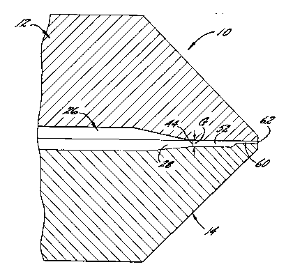
Referring to Figures 1 to 4, a preferred
edge-la,minating apparatus 10 in accordance with the present
invention, is shown. The apparatus is a flat extrusion die
20 conveniently formed by an upper die body 12 and a lower die
b,ody 14. Extrusion die 10 includes flow channels 16,26,36,
. which converge in a common channel 52 prior to a die exit
orifice 62. Convergence of flow channel 36 with flow
channel 16 is shown in Figure 9. Channel 16 is the main
25 channel and channels 26,36 are edge-laminating channels.
Enlarged arrows represent the main flow direction through
the channels and through apparatus 10.
With particular reference to Figure 1, main flow
channel 16 includes a transverse flow-providing chamber 18,
30 which is conveniently a conventional manifold with a
conventional preland channel 20 downstream thereof for
producing substantially equal flow volume of a core or main
stream across the channel width. Alternatively, a
transverse flow-providing chamber of another configuration
3S such as a T-shaped configuration, could be used. Preland
2062127
channel 20 has an output edge 22, which is beneficially
rectilinear.
Edge-laminating flow channel 26 includes a
transverse flow-providing chamber 28, which is
conveniently a conventional fishtail or wedge-shaped
chamber. Alternatively, a transverse flow-providing
chamber of another configuration could be used in
combination with a conventional preland channel. Chamber
28 has an output edge 32, which is beneficially also
rectilinear.
Edge-laminating flow channel 36 includes a
transverse flow-providing chamber 38, which is shown in
Figure 9 and which is conveniently a wedge-shaped chamber.
The configuration of chamber 38 may differ from that of
chamber 28 of edge-laminating flow channel 26. Flow
channel 36 and chamber 38 are optional features of the
present invention, and can be understood from Figure 9 to
have a ,similar relationship to main channel 16 as is
hereafter described for edge-laminating channel 26 and
chamber 28.
Transverse flow-providing chamber 28 of edge-
, laminating channel 26 is disposed exterior to, and in alateral orientation relative to, transverse flow-providing
chamber 18 of main channel 16. A wall member 40 separates
flow channels 16,26.
Referring to Figures 1 and 4, wall member 40 has
a wall portion 42 which begins at output edge 22 of preland
20, and which is generally parallel to the main flow
direction of main channel 16. The wall member terminates
in a point 44. Wall portion 42 has a length L from output
edge 22 to point 44, which may be varied. A wall 46 of
wall member 40 is~a wall of transverse flow-providing
chamber 28 and tapers to point 44.
Flow channels 16,26 converge at a locus of
convergence 50 downstream of point 44, in a common flow
2062127
channel 52. With reference to Figures 1 and 9, the common
flow channel has a width W, which is the sum of the widths
of flow channels 16,26,36 at output edges 22,32,39. The
width of output edge 32 is designated EW in Figure 1.
Referring to Figure 3, preland channel 20 of
main channel 16 suitably has a constant dimension F in the
gap direction, from side to side of the channel. Likewise,
with reference to Figures 1 and 2, at locus of convergence
50, main channel 16 advantageously has a constant gap G,
from side to side. Beneficially, the common flow channel
has a relatively greater gap than preland channel 20;
however, the gaps of the preland channel and the common
flow channel could be the same.
With continued reference to Figure 1, transverse
flow-providing chamber 28 of edge-laminating channel 26 is
advantageously oriented with respect to main channel 16,
such that a transversely spread stream exiting from channel
26 has a main flow direction generally parallel to the main
flow direction of main channel 16. Such an orientation
promotes laminar flow of the converged streams. Any other
o,rientation would permit one flow stream to be driven by
flow pressure into an edge of the other flow stream, and
would result in lateral displacement by the one flow stream
of the other flow stream.
Flow stream convergence immediately downstream
of point 44 produces the convergence of an edge of a
transversely spread stream provided by chamber 18, with an
edge of a transversely spread stream provided by chamber 28
and exiting from flow channel 26. The converging edge of
the edge-laminating stream is at a right angle with respect
to output edge 32 of chamber 28, and generally parallel to
the main flow dir~ction of apparatus 10. Likewise, the
converging edge of the core stream is at a right angle with
respect to output edge 32.
The common flow channel is in fluid
2062127
communication with a land or exit channel 60, which
terminates in an exit orifice 62, shown in Figures 2 and 3.
However, if appropriate, the common flow channel could also
function as the exit channel, in which case the common flow
channel would terminate in the exit orifice.
As best seen in Figures 2 and 3, common flow
channel 52 and exit channel 60 differ from each other in
gap. More specifically, exit channel 60 is of relatively
smaller gap; however, if appropriate, the exit channel
could be of relatively larger gap. Suitably, the exit
channel has a width which is the same as width W of the
common flow channel, and thus the entire length of the flow
passage from point 44 to exit orifice 62 has a constant
width W. The exit orifice, as well as the exit channel,
suitably has a constant gap from side to side.
With particular reference again to Figure 4,
output edge 22 of preland channel 20 beneficially
constitutes a locus of termination of lateral flow for flow
channel 16, upstream of point 44. This advantageous
feature of flow channel 16 is provided by the generally
perpendicular relationship of wall portion 42 of wall
member 40 to the lateral flow direction of main flow
channel 16. Output edge 22 is substantially upstream of,
typically about one-half to two inches above, locus of
convergence 50. From output edge 22 to locus of
convergence 50, only flow in the main flow direction occurs
in the main flow channel.
In the case of flow channel 26, output edge 32
of chamber 28 constitutes a locus of termination of lateral
flow. Point 44 forms output edge 32 in part. The locus of
termination of lateral flow of channel 26 is immediately
prior to locus of convergence 50. Beneficially, the locus
of termination of lateral flow for flow channel 26 is
downstream of the locus of termination of lateral flow for
flow channel 16.
20~2127
As a critical aspect of the present invention,
locus of convergence 50 is located proximate to the exit
orifice. By proximate is meant, for purposes of this
invention, anywhere from 1/8" to about 3" upstream of the
exit orifice, but most typically about 1 to 2 inches
upstream, or with respect to time, from 0.1 to about 5
seconds upstream of the exit orifice, but most typically
about 1 to 3 seconds upstream. Proximate location of the
locus of convergence obviates or reduces the time migration
effect, which would be characterized by lateral migration
or deformation of an edge seam formed by the convergence.
The extent of potential lateral migration or deformation is
a function of, for instance, the respective flow stream
viscosities and flow volumes, and the elapsed time between
convergence and exit of the composite through the exit
orifice. Thus, for a relatively greater difference in flow
stream viscosities, the locus of convergence should be
relativçly closer to the exit orifice, to eliminate the
time migration effect.
In operation, a three layer core stream having
skïn layers of a high performance polymer, is passed
. through main flow passage 16 and undergoes transverse
spreading. The core stream could consist of only a single
layer. Transverse or lateral flow of the core stream is
completed at output edge 22 of preland channel 20. The
core stream then continues to flow in the main flow
direction, to produce a flow stabilizing effect, until it
reaches locus of convergence 50, which is immediately
downstream of point 44.
Concurrently, an edge-laminating stream,
rheologically dissimilar to a layer of the core stream,
passes through and undergoes transverse spreading in
chamber 28 of flow channel 26. Lateral flow of the edge-
laminating stream is completed at output edge 32 of chamber
28, which is formed in part by point 44, and which is
2062127
downstream of the locus of termination of lateral flow of
the core stream.
At locus of convergence 50, edge convergence of
the two streams occurs to form an edge-laminated composite.
Advantageously, each converging stream is at equal flow
volume at the locus of convergence. In other words, each
individual stream has a substantially equal flow volume per
segment of its incremental width across the apparatus, at
locus 50. Beneficially, the converging streams are also at
substantially equal flow volume relative to each other at
the locus of convergence.
Advantageously, no deformation of the edge seam
formed by the converging streams, takes place, and the edge
seam moves in a line generally parallel to the main flow
direction, from point 44 to the exit orifice. As a result,
the edge-laminated composite has an edge seam that is sharp
and well-defined, and an edge that is substantially equal
in width, to width EW of output edge 32.
Figure 5 shows an edge-laminated composite
stream C consisting of layers H,I,J of a core stream M and
o~ edge streams N,0. Edge seams K,P separate edge streams
. N,0 from core stream M.
Edge stream O is conveniently the same polymer
as edge stream N; however, the edge streams could be
different polymers. With reference also to Figure 9, edge
stream O passes through and undergoes transverse spreading
in chamber 38 of flow channel 36 prior to convergence at a
locus 70 with core stream M. Locus 70 is conveniently the
same distance from the exit orifice as is locus 50. Edge
stream 0 is at a relatively greater flow volume than the
core stream at locus 70. As a consequence, edge stream O
of the composite is of greater width than the width of an
output edge 39 of channel 36. Beneficially, edge seam P is
free of deformation, and, like edge seam K, is suitably
2062127
generally perpendicular to a web face R of composite C.
If desired, a composite having an edge stream O
of less width than the width of output edge 39 could be
formed. This result could be achieved by providing stream
M with a relatively greater flow volume than stream o at
convergence 70.
As explained earlier, the relative disposition
of locus of convergence 50 to exit orifice 62 is a critical
aspect of the present invention. Accordingly, in
accordance with the present invention, an appropriate
location is selected for locus 50, such as about one and
one-half inches upstream of exit orifice 62. Thereafter,
length L of wall portion 42 of wall member 40 is
established to move the transverse flow-providing chamber
and output edge of the main flow channel relatively closer
to, or further away from, the locus of convergence, to
decrease or increase the time for stabilizing flow in the
main flow channel prior to convergence. Suitably, the
length of wall portion 42 is about 3/4 inch. Reference is
now made to the embodiment of Figure 6, which illustrates a
t~ansverse flow-providing chamber 118 and an output edge
122 situated relatively further away from a locus of
convergence 150 than chamber 18 and edge 22 are disposed
from locus of convergence 50 in the embodiment of Figure 1.
Like parts of the embodiment of Figure 6, as
well as of other embodiments depicted in the drawing, have
been designated with numbers corresponding to like parts of
the embodiment of Figure 1. For sake of brevity, details
previously described are not repeated.
In a further variation, a portion of exit
channel 60 may be of greater length in the main flow
direction, than th,e remainder of the exit channel. Figures
7 and 8 show a portion 264 of an exit channel 260 of
greater length in the flow path of an edge-laminating flow
35 channel 226. A dashed line from a point 244 to an edge 268
2062127
of portion 264, and from edge 268 to an exit orifice 262
(shown in Figure 8) indicates a common boundary of the flow
path of edge-laminating channel 226 and of the flow path of
a main flow channel 216, when the converging streams have
equal flow volumes relative to each other. This variation
is useful when the viscosity of the stream in the main
channel is greater than the viscosity of the stream in the
edge-laminating channel, and the proximate location of a
locus of convergence 250 is not maximized.
Conversely, exit channel 260 could have a
portion of greater length in the flow path of main channel
16. This variation is useful when the viscosity of the
stream in the main channel is less than the viscosity of
the stream in the edge-laminating channel.
With reference to Figure 10, which shows a
modification of the extrusion die of Figure 6, a removably
mounted assembly 180 may provide a transverse flow-
providi,ng chamber 128 of edge-laminating channel 126 and a
portion of a wall member 140. Figure 10 also shows a
variation of wall member 140, in which the wall member has
a~ extended length. This variation provides for completion
. of substantially all transverse flow of the edge-laminating
stream substantially upstream of a locus of convergence
150.
In the preceding description of the present
invention, there are shown and essentially described only
preferred embodiments of this invention, but as mentioned
above, it is to be understood that the invention is capable
of changes or modifications within the scope of the
inventive concept expressed herein. Several changes or
modifications have been briefly mentioned for purposes of
illustration.