Note: Descriptions are shown in the official language in which they were submitted.
27955-lOD
ECCENTRIC D~ILLING TOOL
This is a division of our co-pending Canadian Patent
Application No. 2,013,786.
The present invention relates to eccentric drilling
tools for combined rotary and percussive drilling in earth and in
rock covered by overburden concurrently with a casing tube
~ollowing the drilling tool downhole, and more particularly to the
type of such drilling tools wherein a guide member is rotatably
centered by the mouth of the casing tube, a pilot bit at the
forward end of said tool is supported by the guide member and
provided with axially oriented hard metal pilot insert means
peripherally thereon directed to define the diameter of the pilot
hole to be cut during drilling, a laterally extending eccentrlc
bit behind said pilot bit on the tool carries axially oriented
hard metal reamer insert means at the eccentric top thereof
directed to ream up the pilot hole to the maximum diameter of the
hole drilled, and the eccentric bit is movably supported relative
to said guide member between a drilling position, in which the
eccentric bit projects laterally beyond said casing tube so as to
drill jointly with the pilot bit a hole larger than the casing
tube, and a retra~ted position, in which the drilling tool can be
retracted or lowe7ed through the casing tube.
Drilling tools of this type are disclosed inter alla in
U.S. Patent Publications 3,753,470, 3,848,683, and 4,440,244. In
these tools the greater part of the drilling work falls on the
insert means that have the longest distance to travel during work,
i.e. on the reamer insert means at or close to the maximum
~ 7955-lOD
diameter worked. In that region primarily the insert means
leading in the rotational direction of the tool is the one that
has to, or in case of radially staggered plural insert means, are
the ones that have to, carry the maximum load being the first to
"break up" the hole radially to its full dimension. Under the
actlon of the rotary drive torque and the vibrations during
drilling, the load on these leading inserts tends to turn the
eccentric bit in the rotational drilling direction with the
leading insert means as central point. As a result there is
created an undesirable wear of the pilot bit towards a gradual
reduction of the maximum diameter drilled until finally the casing
tube gets stuck.
It is the main object of the invention to remedy the
problem outlined. The invention provides eccentric drilling tool
for combined rotary and percussive drilling in earth and in rock
covered by overburden concurrently with a casing tube following
the drilllng tool downhole, said tool comprising a guide member
rotatably centered by the mouth of said casing tube, a pilot bit
having frontal quadrants, said pilot bit positioned at the forward
end of said tool supported by said guide member and provided with
a plurality of axially oriented hard metal pilot insert means
peripherally thereon directed to define the diameter of the pilot
hole to be cut during drilling, a laterally extending eccentric
bit behind said pilot bit on said tool and having a plurality of
axially oriented hard metal reamer insert means at an eccentric
top thereof directed to ream out the pilot hole to the maximum
diameter of the hole drilled, sald eccentric bit being movably
27955-lOD
supported relative to said guide member between a drilling
position, in which the eccentric bit projects laterall~ beyond
said casing tube so as to drill jointly with said pilot bit a hole
larger than said casing tube, and a retracted position, in which
the drilling tool can be retracted or lowered through the casing
tube, and one of the frontal quadrants of the pilot bit being void
of perlpheral diameter cutting pilot inserts, said diametrically
non-cutting quadrant being dlsposed diame~rically opposite to the
reamer insert means of the eccentric bit that leads in the
rotational direction of the tool.
The inventive solution can be optimised by an
advantageous application of hard metal buttons as insert means.
The inventive solution may be applied in an eccentric drilling
tool of improved design ahle to support the insert buttons with
increased sturdiness.
An embodiment of the invention is described hereinafter
with reference to the enclosed drawings, wherein:-
Fig. 1 shows the drilling tool in cross section duringpassage of the guide member through the casing tube with a drill
bit, shown in side view, hanging down there$rom in retracted
position;
Fig. 2 shows a corresponding view with the drill bit in
drilling position adjacent to the guide memher which is supported
in the casing shoe at the mouth of the casing tube;
Fig. 3 is a rear end view of the drill blt in Fig. 2;
Fig. 4 is a side view of the guide member in Fig. 2;
Fig. 5 is a side view o$ the drill bit in Fig. 1 seen in
27955-lOD
the direction of a~rows 5-5; and
Fig. 6 is a somewhat enlarged end view of the drill bit
and guide member in Fig. 2 seen in the directlon of arrows 6-6.
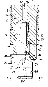
The guide member 10 is in the usual way coupled to a
drill strlng extending through the casing tube 11. In ~he example
shown the drill strlng rotates the guide member 10 in the
clockwlse dlrection when vlewed from above and delivers impact
energy thereto from a tophammer above ground or from a do~nhole
drlll coupled in impact generatlng position between the drill
string and the guide member 10. The drill string and the parts
associated therewith are conventional and not shown in the
drawlngs.
The guide member 10 has a circularly cylindrical guide
portlon 12 whlch with a centering fit is guided by the mouth of
the caslng tube 11 for rotation coaxially with the drilling axis
16. In the example shown illustrating drive by a down-the-hole
drill, the mouth of the casing tube has welded thereon a guide
shoe 13, which provides an internal shoulder 14 in the casing tube
and a circularly cylindrical guide opening 19 for the guide
portion 12. The guide member 10 has axial abutments 15 at the
rear thereon abutting on the shoulder 14 whereby part of the
impact power from the downhole drill is transmitted to dri~e down
the casing tube 11, Fig. 2.
The drill bit 20 incorporates a rear shaft 21 in one
piece with an eccentric portion or bit 22 and a pilot bit 23. The
shaft 21 is pivotally journalled in the guide member 10 in and
around the axis 17 of an eccentric bore 24 extending in laterally
27955-lOD
spaced and parallel relation to the drilling axis 16. The pilot
bit 23 in its turn is centered on an axis 18 which is parallel
with the axas 16,17 but has the double lateral spacing to ~he
drilling axis 16 when compared to the shaft axis 17.
When the drill bit 20 takes an angular positlon in the
bore 24 with the pilot bit axis 18 at such maximal dis~ance from
the drilling axis 16, Fig. 1, both the pilot bit 23 at one side of
the shaft axis 17 and the eccentric bit 22 at the opposite side
thereof are directed such that both bits fall within the outer
contour of the cylindrical guide portion 12 and thus can press
freely through the guide opening 19 of the guide shoe 13 as shown
in Fig. 1.
When the drill bit is turned about 180 degrees from the
aforementioned position the axes 16,18 coincide. The pilot bit 23
thus becomes coaxial with the drilling axis 16 and the eccentric
bit 22 is projected laterally sufficiently beyond the outer
contour of the guide shoe 13 so as to be able to drill a hole
larger than the casing tube 11. Such position is illustrated in
Fig. 2.
In the radially retracted position of Fig. 1 the drill
bit 20 hangs freely in the guide member 10, being retained axially
form-bound thereto by follower means such as a cam follower 28.
In the example shown the cam follower is a pin 28 inserted in a
transverse bore 27 in the guide member 10 and projecting into the
bore 24 for cooperation with an arresting groove 29 in the rear
shaft 21. With the drill bit 20 hanging freely in retracted
position, the pin 28 will engage the arresting groove 29 and is
27955-lOD
thereby kept bidirectionally arrested form-bound agalnst rotation
relative to the guide member 10 so as to be able to pass safely
through the casing tube.
The arresting groove 29 opens from behind into a
peripheral rear end groove 30 in the shaft 21. When the drill bit
20 meets the surface to be drilled, the cam follower 28 enters the
end groove 30. The latter allows an angular form-restxicted
movement of about 90 degrees to be performed by the guide member
10 relative to the drill bit 20 clockwise in the drill rotating
direction until the cam follower 28 reaches a forwardly directed
cam groove 31. Therein the cam follower 28 is allowed to move
axially in forward direction until met by a peripheral forward end
groove 32. Continued rotation in the drill rotating direction of
the guide member 10 some further 90 degrees locks the cam follower
28 form-bound in axial direction ln and by the forward end groove
32 as shown in Fig. 2. The illustrated helical surface shown
opposite to the straight one of cam groove 31 is generated when
said groove is milled by a cylindrical tool and comes in helpful
for guiding the complex movement of the drill bit 20.
The position in Fig. 2 is the drilling position of the
drill bit 20. The shoulder 14 of guide shoe 113 or (when top-
hammer drilling is practiced, and the guide member 10 is centered
by the interior of the casing tube 11 itself) the predetermined
bound axial relationship between the drill string and the casing
tube 11 has to define such an exposure of the guide por~ion 12 in
front of the forward edge of the casing shoe 13 or casing tube 11
that the distance therebetween and between back 40 of the
27955-lOD
eccentric bit 22 approximately will be equal to or somewhat larger
~han the length of the pilot bit 23. A stuck casing tube will
thus be unable to prevent lifting of the pilot bit 23 from lts
leading hole and the drill bit 20 is then free to be turned into
the retracted position. During the peripheral and axial relative
movement of the drill bit 20 from the position in Fig. 1 the cam
grooves 30-32 and the pin 28 function as cooperating cam and
follower means whereby the drill bit is gulded and is in the
drilling position of Fig. 2 brought adjacent to and in front of an
axially protruding shoulder 33 on the guide member 20. During
drilling the shoulder 33 abuts against a mating transverse
abutment 34, shown in Fig. 3, and transmits drilling rotation
(arrow 7) to the drill bit 20 simultaneously with presslng the cam
~ollower 28 into and locking it in the forward end groove 32. In
the drilling position of Fig. 2 the end 38 of shaft 21 is in
engagement with the bottom of bore 24 and concurrently therewith
the axial face 39 of the guide member also transmits impact power
to the back 40 of the eccentric bit 22.
The form-bound guidance of the drill blt 20 allows, due
to the axial movability of the follower 28 in cam groove 31, that
powerful blows by cam follower 28 can be directed upward against
the rear cam groove 30 in order to hammer free a stuck drill bit
20. The pivotal movement and a rounded surface at 35 on the
abutment 34, Fig. 3, allows turning movement of the guide member
10 to bring follower 28 into axially movable positlon even with
the drill bit stuck, notwithstanding that the shaft 21 then takes
eccentric position. Incidentally, in this and in the locked
27955-lOD
drilling position the casing tube 11 can be knocked upward from a
jammed position by means of back 40 (Fig. 3) of the drill bit 20.
Repeated short raising of the drill bit 20 in lts drilling
position and subsequent blowing eases cleaning of the working
surface and of the ~orward portion of the drill bit 20 from clay.
Positionlng of the drill bit 20 in axially retracted fixed angular
position above a hindering stone edge allows crushing or knocking
aside the stone by blows without drill rotation so that drilling
then can be continued the normal way.
The drilling tool preferably drills by means of tungsten
carbide buttons fitted on the front surfaces of the pilot and
eccentric bits 23,22. Fig. 6 shows the preferred disposition of
the tungsten carbide buttons on the drill bit 20. The eccentric
bit 22 has a level front surface 44, a laterally protruding partly
conical rearwardly-inwardly slanting mantle surface 45 having a
central cone axls at 46, and a sickle shaped transition chamfer 47
that joins the front surface 44. The chamfer 47 carries at the
maximal protrusion or central plane (through the axes 17,18) of
the eccentric bit 22 two or, as in the example shown, three
outwardly slanted symmetrically arranged hard metal buttons
48,49~50 which at drilling cut the maximum diameter of the tool.
Leading in the rotational direction (arrow 8) is positioned an
axial button 51 on the front surface 44 adjacent to and tangential
to its periphery, i.e. the inner side of chamfer 47. A further
axially directed button 52 can be inserted into surface 44
trailing in the rotational direction after the oblique peripheral
buttons 48-50. The buttons 51,52 are spaced from the mantle of
27955-lOD
the pilot bit 23 in order to improve during drilling the crushing
work around the rim of the pilot hole.
The pilot blt 23 i6 in the Fig. 6 posltion coaxial with
the guide member 10 and has forwardly a circumferential chamfer 56
carrying thereon a number of outwardly slanting peripheral buttons
57,57I_57III that define the diameter of the pilot hole drilled.
The frontal surface of the pilot bit 23 carries a few, for example
two, axially directed buttons 58.
During drilling a predominating part of the drilllng
work falls on the two leading buttons 51,48 of the eccentric bit
22. Study of the wear of the pilot portion shows that the load
acting on these buttons tends to turn the back of the eccentric
bit 22 in the rotational direction (arrow 8) with the buttons
51,48 as center. This results in a high radial pressure in a
direc~ion diametrlcally opposite to the buttons 51,48, a load tha~
is taken up by the centering mantle surface of the pilot bit 22 in
the quadrant or peripheral section of the pilot hole opposite to
the buttons 51,48. In that section (between the buttons 57,57I in
Fig. 6) therefore no diameter cutting buttons can be allowed since
the radial load otherwise would rapidly cause a deviation of the
pilot hole in a dlrection that in due course would reduce the
maximum diameter cut by the eccentric bit 22, so that the casing
tube 11 finally would become stuck. Wear on the corresponding
perlpheral portion of the pilot bit 23 has an analogous effect and
therefore the mantle surface of the pilot bit 23 at said its
forward best centering portion is provided with one or a few
gauging buttons 59, preferably two coplanar blunt buttons of hard
27955-~OD
metal as shown in the example. The pilot bit 23 must have a
length assuring that a sufficient guiding surface is provided
around the bottom of the pilot hole spaced in front of its
substantially funnel shaped mouth that is crushed up and widened
by the buttons 51,52.
Flushing medium, for example exhaust air from the
downhole drill, is supplied to a passage 62 in the guide body 10
and led on to a passage 63 in the drill bit 20 and from ~here to
branch passages terminated by openings 64,65 on the front surface
44 of the eccentric bit 22, to ejector branch passages directed
rearwards each into an axial groove 66,67 on the mantle 45 of the
eccentric bit 22, to a branch passage terminated by an opening 68
in the front of the pilot bit 23, as well as into a further branch
passage terminated by opening 69, Fig. 1,3, for flushing clean the
area in front of shoulder 33.
The guide member 10 has preferably three hollowed outr
shallow straight flushing grooves 71 in its guide portion 12. The
grooves 71 a.re somewhat narrowed at their rear and are open
between the lugs 15. Rearwardly directed ejector openings 72 open
up between these lugs 15 and are connected to the interior
flushing passage 62 of guide member 10 so as to lmprove flushing
of the grooves 71. At their forward ends grooves 71 are ending
blindly into the periphery of the guide portlon 12 before reaching
the forward edge 39 of the guide member 10, Fig. 4. A fourth
similar flushing groove 70 extends axially from front to rear
along the entire guide member 10 and is shown from below in Fig.
6. The flushing groove 70 is connected so as to ven~ the flank of
27955-lOD
the eccentric bit 22 in Fig. 6 that precedes in the rotational
direction (arrow 8) the maximally loaded buttons 51,48-50 during
drllling, whereas the flushing openings 64,65 open out within the
working area of these huttons. As a result there is provided an
effective cleaning by a flushing medium stream directed
predominantly in counter direction to the rotation (arrow 8),
firstly along the front sur$aces 44,47 of the eccentric bit 22,
then, guided by an axially directed notch 73 in its mantle past
the front face of shoulder 33, in behind the back of bit 22, and
finally out through the flushing groove 70. Part of the stream is
simultaneously directed forward in the rotational direction via a
guide groove 74, directly towards flushing groove 70 in order to
counteract recirculation of debris around pilot blt 23. The guide
groove 74, Figs. 1,2,6 is scoop-shaped in the rotationally leading
flank of the eccentric bit 22 in order to provide a shovelling
favourable in clay-bound earth. As shown, the guide groove may be
extended axially through the pilot bit 23 for improved guiding of
the flushing stream.
The three blindly ending flushing grooves 71 extend in
drilling position of guide member 10 out in front of the forward
edge of the casing shoe 13 and effect removal of the mixture of
flushing medium and drill cuttings expelled axially from inter
alia the axial grooves 66,67 and otherwise to the enlarged drill
hole around the protruding front end of guide portion 12, thereby
easing the driving down of the casing tube 11. At a tendency of
the flushing groove to become choked for example by clay, the
guide member 10 can be retracted to bring the back 40 of the
27955-lOD
eccentric portion 22 into abutting relation agalnst the casing
shoe 13. In case of downhole drilling the supply of flushing
medium will simultaneously herewith be increased due to the so
called hanging reaction of the downhole drill. At such retraction
the blind flushlng grooves 71 become closed by the interior
surface of the casing shoe 13 and that renders a reinforced
blowgun-like clean-blowing of the sole flushin0 groove 70 and of
the drill parts in front thereof.
In case of need the available venting cross section can
be increased by providing further permanently open ~lushing
grooves 70 or simply by the provision of a transverse notch 75,
Fig. 6, in the front of the guide portion 12, whereby the flushing
groove 70 is jolned to an adjacent blind groove 71, preferably the
one trailing in the rotational direction tconcealed in Fig. 6) as
compared to flushing groove 70.
The invention is not restricted to the described
drilling tool but can be modified and applled inter alia in the
drllling tool variants referred-to at the outset of this
description or in other applications, all within the scope of the
appended claims.