Language selection

Search

Patent 2062500 Summary

Third-party information liability

Some of the information on this Web page has been provided by external sources. The Government of Canada is not responsible for the accuracy, reliability or currency of the information supplied by external sources. Users wishing to rely upon this information should consult directly with the source of the information. Content provided by external sources is not subject to official languages, privacy and accessibility requirements.

Claims and Abstract availability

Any discrepancies in the text and image of the Claims and Abstract are due to differing posting times. Text of the Claims and Abstract are posted:

  • At the time the application is open to public inspection;
  • At the time of issue of the patent (grant).
(12) Patent: (11) CA 2062500
(54) English Title: WELL LIGHT
(54) French Title: APPAREIL D'ECLAIRAGE
Status: Expired and beyond the Period of Reversal
Bibliographic Data
(51) International Patent Classification (IPC):
  • F21V 21/14 (2006.01)
  • F21S 8/02 (2006.01)
  • F21V 21/22 (2006.01)
  • F21V 21/30 (2006.01)
(72) Inventors :
  • PORTER, DAVID (United States of America)
  • GARBER, THOMAS A. (United States of America)
(73) Owners :
  • L.D. KICHLER CO. (THE)
(71) Applicants :
(74) Agent: GOWLING WLG (CANADA) LLP
(74) Associate agent:
(45) Issued: 1994-11-22
(22) Filed Date: 1992-03-09
(41) Open to Public Inspection: 1993-07-09
Examination requested: 1993-03-29
Availability of licence: N/A
Dedicated to the Public: N/A
(25) Language of filing: English

Patent Cooperation Treaty (PCT): No

(30) Application Priority Data:
Application No. Country/Territory Date
814,993 (United States of America) 1992-01-08

Abstracts

English Abstract


A lighting apparatus is disclosed which includes a lighting source suspended
inside a cylindrical housing. The light source is connected to a device for suspen-
ding the light source within the housing such that the housing can be removed
from the housing by lifting the device and disengaging it from the housing. The
light source may be suspended inside the housing in varying configurations to
provide different illumination patterns.


Claims

Note: Claims are shown in the official language in which they were submitted.

THE EMBODIMENTS OF THE INVENTION IN WHICH AN EXCLUSIVE
PROPERTY OR PRIVILEGE IS CLAIMED ARE DEFINED AS FOLLOWS:
1. A lighting apparatus comprising:
a) an electric light source;
b) a housing having a tubular wall and an outlet end through which light
from said source may pass;
c) a light supporting structure for suspending said light source within said
housing, said structure including a member having first and second ends, said ends
having first and second hooks, respectively, for engaging the wall of said housing at
said outlet end, wherein said source is connected to said member at a location closer
to one of said hooks than the other by a predetermined distance such that the location
of the light source within the housing may be selectively varied between a first depth
when said first hook is chosen to suspend the source and a second depth when said
second hook is chosen to suspend said source.
2. A lighting apparatus as claimed in claim 1 wherein said light source is
pivotally connected to said member such that it may be rotated to cast light in the
direction of the outlet end regardless of which hook is chosen to suspend the source.
3. A lighting apparatus as claimed in claim 1 wherein said outlet end includes asidewall opening for casting light in a lateral direction.
4. An outdoor lighting apparatus comprising:
a) an electric light source;
b) a housing having a tubular wall and an outlet end through which light
from said source may pass, said housing being adapted to rest partially buried in the
ground with its longitudinal axis in a generally vertical position;
c) a light supporting structure for removably suspending said light source
within said housing, said structure including a member having first and second ends,
said ends having first and second hooks, respectively, for engaging the wall of said
housing at said outlet end, wherein said source is pivotally connected to said member
at a location closer to one of said hooks than the other by a predetermined distance
such that the location of the light source within the housing may be selectively varied

between a first depth when said first hook is chosen to suspend the source and a
second depth when said second hook is chosen to suspend said source and wherein
said light supporting structure is inverted when its suspension is changed from one
hook to the other.
5 . A lighting apparatus as claimed in claim 4 wherein said light source may be
pivoted about said pivotal connection to cast light in the direction of the outlet end
regardless of which hook is chosen to suspend the source.
6. A lighting apparatus as claimed in claim 5 wherein said outlet end includes asidewall opening for casting light in a lateral direction.

Description

Note: Descriptions are shown in the official language in which they were submitted.


~`
2062S00
-
12-541
WELL LIG~IT
Background of the Invention
1. Field of the Invention
The present invention relates to outdoor lighting fixtures, and more
particularly, to outdoor lighting fixtures which have adjustable illumination pat-
terns.
2. Description of the Related Art
The use of outdoor lighting fixtures has become popular for illuminating
buildings, gardens, pathways and entrance ways. Landscape architects frequently
use partially buried outdoor well lights for illuminating trees and shrubs, and for
providing silhouettes and shadowing effects.
Existing well lights have been found deficient in durability, versatility,
adjustability, and ease of maintenance. Existing well lights are typically limited in
their ability to vary the illumination pattern. Often, the light source is limited to a
few degrees of pivotal motion. Typically, existing well lights require that screws or
other fasteners be removed to replace the light bulb. Since the lights are exposed
to the weather, the fasteners often become corroded m~king bulb replacement
difficult. Existing well lights are also susceptible to breakage from lawn mowerwheels among other things.
Summary of the Invention
Basically, the lighting fixture comprises a housing well having an outlet end,
a light source, and apparatus removably suspending the light source within the
well. The suspending apparatus has a weight supporting portion supporting the
weight of said light source from said well so that said light source can be removed
from said outlet end by disene~ging said weight supporting portion from the
housing well

i
2 2062~00
Brief Description of the Drawings
A preferred embodiment of the invention is shown in the accompanying
drawings in which:
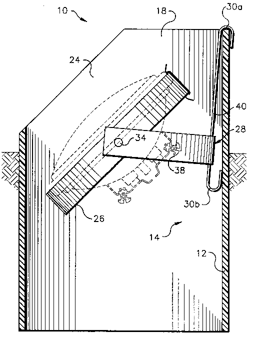
Figure 1 is a side elevation view, partly in cross section, of a well light
constructed in accordance with the present invention;
Figure 2is a side elevation view, partly in cross section, of the light of
Figure 1 in a different position;
Figure 3 is a side elevation view, partly in cross section, of the well light ofFigure 1 in a different configuration;
Figure 4 is a side elevation view, partly in cross section, of the well light ofFigure 1 in a different configuration;
Figure 5 is a plan view as seen al)~r~"~i"~tely from the plane indicated by
line 5-5 in Figure 1; and
Figure 6is a side elevation view in full cross section with the bulb removed.
Description of the Preferred Embodiment
The well light 10 embodying the present invention includes a housing wéll
12, a suspension fixture 14 which is adjustably supported inside the housing well
12, and a light bulb 16. The housing well 12 is partially buried in the ground with
one end exposed as an outlet 18 for the light. Power is supplied to the light bulb
16 by wires 20 connected to a set of terminals 22.
The housing 12 comprises a high-strength polyethylene cylinder. The cylin-
der is cut-away on one side to provide a lateral opening 24 for light. Thus, if it is
desired to provide a lateral beam of light, the cut-away end may be used as the
light outlet end 16 as shown in Figures 1 and 2. If desired, the cut-away end may
be buried in the ground as shown in Figures 3 and 4 and the opposite end may be
used as the outlet 18. The high-strength polyethylene housing 12 serves to houseand protect the light bulb 16 from breakage.
The suspension fixture 14 comprises a light bulb retainer ring 26 and a
hanger member 28 connected to the retainer ring 26. The fixture 14 is suspended
inside the housing 12 by a weight-supporting member or hook 30a on the hanger
member 28 and is readily removable for bulb replacement. The bulb 16 and

~ `l~
2062500
fixture 14 can be removed from the outlet end 18 of the housing well 10 by
diseng~ging the hook 30a from the edge of the housing well 12 and lifting. The
fixture 14 may be hung from either of two hooks 30a, 30b depending on the
desired lighting pattern. One hook 30a suspends the bulb lower in the housing
well than the second hook 30b as seen in Figures 1, 2, and 4.
The retainer ring 26 is plefel~bly stainless steel. A plurality of retainer
clips 32 are attached to the ring 26 to retain the bulb 16 within the ring 26. The
clips 32 apply a spring force to the bulb 16 to hold it within the ring 26. The
retainer clips 32 permit the bulb 16 to be readily released. Manual application of
pressure to one side of the bulb causes the peripheral edge of the bulb 16 to slide
past the retainer clips 32. The ring 26 is pivotally connected to the hanger
member 28 by a pair of pivot joints 34, 36 as best seen in Figure 5.
The hanger member 28 comprises a semi-circular stainless steel member 38
and a hook member 40 fixed thereto. The semi-circular member 38 is pivotally
connected to the ring 26 at the pivot joints 34, 36. Elastomeric washers 42 are
placed between the ring 26 and the semi-circular member 38 at each pivot joint
34, 36.
The hook member 40 comprises a stainless steel strap having the first and
second hooks 30a, 30b formed at its respective ends. The hook member 40 is con-
nected to the middle of the semi-circular member 38 at a point which is closer to
one hook 30b than the o~ther 30a. Each hook 30a, 30b is adapted to engage the
edge of the housing well 12 to suspend the fixture 14 within the housing well 12 as
shown in Figures 1-6. The bulb 16 and ring 26 are rotated to aim the light toward
the outlet 18 regardless of which hook 30a, 30b is being used. Thus, one way of
changing the lighting pattern is to remove the fixture 14 from the housing 12,
rotate the ring 26 about the axis of the pivot joints 34, 36 approximately 180 de-
grees, invert the fixture 14, and re-hook it to the housing 12 from the oppositehook. The lighting pattern is narrowed by positioning the fixture deeper in the
housing well and broadened by positioning it nearer to the outlet 18.
The well light 10 constructed according to the invention is corrosion
resistant and durable as a result of the stainless steel fixture 14 and the poly-
ethylene housing 12. The light is versatile and readily adjustable due to the
-

~ ~ 2062500
suspension fixture 14 configuration. In addition, the parts are simple and easy to
construct at low cost.
While a preferred embodiment of this invention has been described in
detail, it will be apparent that certain modifications or alterations can be made
without departing from the spirit and scope of the invention as set forth in theappended claims.

Representative Drawing
A single figure which represents the drawing illustrating the invention.
Administrative Status

2024-08-01:As part of the Next Generation Patents (NGP) transition, the Canadian Patents Database (CPD) now contains a more detailed Event History, which replicates the Event Log of our new back-office solution.

Please note that "Inactive:" events refers to events no longer in use in our new back-office solution.

For a clearer understanding of the status of the application/patent presented on this page, the site Disclaimer , as well as the definitions for Patent , Event History , Maintenance Fee  and Payment History  should be consulted.

Event History

Description Date
Inactive: IPC from MCD 2006-03-11
Time Limit for Reversal Expired 2003-03-10
Letter Sent 2002-03-11
Grant by Issuance 1994-11-22
Application Published (Open to Public Inspection) 1993-07-09
All Requirements for Examination Determined Compliant 1993-03-29
Request for Examination Requirements Determined Compliant 1993-03-29

Abandonment History

There is no abandonment history.

Maintenance Fee

The last payment was received on 

Note : If the full payment has not been received on or before the date indicated, a further fee may be required which may be one of the following

  • the reinstatement fee;
  • the late payment fee; or
  • additional fee to reverse deemed expiry.

Please refer to the CIPO Patent Fees web page to see all current fee amounts.

Fee History

Fee Type Anniversary Year Due Date Paid Date
MF (patent, 6th anniv.) - standard 1998-03-09 1998-02-13
MF (patent, 7th anniv.) - standard 1999-03-09 1999-02-10
MF (patent, 8th anniv.) - standard 2000-03-09 2000-02-14
MF (patent, 9th anniv.) - standard 2001-03-09 2001-02-12
MF (application, 2nd anniv.) - standard 02 1994-03-09
Owners on Record

Note: Records showing the ownership history in alphabetical order.

Current Owners on Record
L.D. KICHLER CO. (THE)
Past Owners on Record
DAVID PORTER
THOMAS A. GARBER
Past Owners that do not appear in the "Owners on Record" listing will appear in other documentation within the application.
Documents

To view selected files, please enter reCAPTCHA code :


To view images, click a link in the Document Description column. To download the documents, select one or more checkboxes in the first column and then click the "Download Selected in PDF format (Zip Archive)" or the "Download Selected as Single PDF" button.

List of published and non-published patent-specific documents on the CPD .

If you have any difficulty accessing content, you can call the Client Service Centre at 1-866-997-1936 or send them an e-mail at CIPO Client Service Centre.


Document
Description 
Date
(yyyy-mm-dd) 
Number of pages   Size of Image (KB) 
Cover Page 1994-11-22 1 15
Description 1994-11-22 4 158
Abstract 1994-11-22 1 13
Claims 1994-11-22 2 64
Drawings 1994-11-22 6 157
Representative drawing 1999-06-16 1 32
Maintenance Fee Notice 2002-04-08 1 179
Fees 1997-02-13 1 53
Fees 1996-02-12 1 43
Fees 1995-02-10 1 46
Fees 1994-01-26 1 32
Prosecution correspondence 1992-05-21 1 28
Prosecution correspondence 1993-03-29 1 39
Courtesy - Office Letter 1993-04-23 1 51
PCT Correspondence 1994-09-09 1 43
Prosecution correspondence 1993-07-07 3 121