Language selection

Search

Patent 2062597 Summary

Third-party information liability

Some of the information on this Web page has been provided by external sources. The Government of Canada is not responsible for the accuracy, reliability or currency of the information supplied by external sources. Users wishing to rely upon this information should consult directly with the source of the information. Content provided by external sources is not subject to official languages, privacy and accessibility requirements.

Claims and Abstract availability

Any discrepancies in the text and image of the Claims and Abstract are due to differing posting times. Text of the Claims and Abstract are posted:

  • At the time the application is open to public inspection;
  • At the time of issue of the patent (grant).
(12) Patent: (11) CA 2062597
(54) English Title: AUXILIARY MEANS FOR FASTENING A CAPPING ON BONE TISSUE OR THE LIKE
(54) French Title: ELEMENTS AUXILIAIRES POUR FIXER UNE COURONNE SUR UN TISSU OSSEUX OU AUTRE TISSU SEMBLABLE
Status: Expired and beyond the Period of Reversal
Bibliographic Data
(51) International Patent Classification (IPC):
  • A61B 17/86 (2006.01)
  • A61B 17/80 (2006.01)
  • A61F 2/00 (2006.01)
  • A61F 2/28 (2006.01)
(72) Inventors :
  • BUSER, DANIEL (Switzerland)
  • SUTTER, FRANZ (Switzerland)
  • MUNDWILER, ULRICH (Switzerland)
(73) Owners :
  • INSTITUT STRAUMANN AG
(71) Applicants :
  • INSTITUT STRAUMANN AG (Switzerland)
(74) Agent: NORTON ROSE FULBRIGHT CANADA LLP/S.E.N.C.R.L., S.R.L.
(74) Associate agent:
(45) Issued: 1999-08-31
(22) Filed Date: 1992-03-10
(41) Open to Public Inspection: 1992-09-12
Examination requested: 1995-11-21
Availability of licence: N/A
Dedicated to the Public: N/A
(25) Language of filing: English

Patent Cooperation Treaty (PCT): No

(30) Application Priority Data:
Application No. Country/Territory Date
720/91 (Switzerland) 1991-03-11

Abstracts

English Abstract


A means for fastening a capping on bone tissue or the
like over an area of original, locally depressed, chipped or
fractured tissue to promote the growth of additional tissue is
disclosed, comprising generally, a pin which has, at one end, a
bead for attachment of a foil and, at the other end, an external
thread for threading into the original tissue or bone. Between
the bead and the thread is a smooth-walled segment whose
diameter is preferably larger than the diameter of the external
thread.


Claims

Note: Claims are shown in the official language in which they were submitted.

The embodiments of the invention in which an exclusive property
or privilege is claimed are defined as follows:
1. An auxiliary means for fastening a cover over an area
of original, locally depressed, chipped for fractured tissue to
promote the growth of additional tissue, comprising:
a pin including:
external thread on one end of the pin;
a bead on the other end;
internal thread, within said pin, at said other
end;
a cylindrical, smooth-walled segment between said
bead and the external thread, wherein the
diameter of said segment is greater than or equal
to the diameter of the external thread;
a foil which may be positioned over said area and over
the bead of the pin; and
a cap screw means for maintaining said foil over said
area and said pin, wherein said cap screw is detachably
securable to said pin.
2. The auxiliary means of Claim 1, wherein said tissue is
bone.
3. The auxiliary means of Claim 1, wherein said
engagement face is an internal square.
4. The auxiliary means of Claim 1, wherein said
engagement face is an internal hexagonal surface.
5. The auxiliary means of Claim 1, wherein said
cylindrical segment has an axial length of at least about 2 mm.
6. The auxiliary means of Claim 1, wherein the length of
the segment with the internal thread is about 3 to 5 mm.
-7-

7. The auxiliary means of Claims 1, 3, 5 and 6, wherein
the external thread has a diameter of about 1.2 mm.
8. The auxiliary means of Claim 7, wherein the
cylindrical segment has a diameter of about 1.8 mm.
9. The auxiliary means of Claim 8, wherein the bead has a
diameter of about 2.5 mm.
10. The auxiliary means of Claims 1, 3, 5 and 6, wherein
the diameter of the bead of the cap screw corresponds to the
diameter of the bead of the pin.
11. The auxiliary means of Claim 1, wherein the cap screw
has an engagement face for application of a screwdriver, wherein
said engagement is configured identically to an engagement face
which is placed at the bead for application of a screwdriver.
-8-
,: i

Description

Note: Descriptions are shown in the official language in which they were submitted.


2062597
Auxiliary Means for Fastening a Capping on
Bone Tissue or the Like
FIELD OF THE INVENTION
The present invention is directed to promoting the
growth of tissue in localized areas and more particularly to the
fastening of a capping on a bone, such as a jawbone, to promote
the formation of new tissue.
BACKGROUND OF THE INVENTION
Bones, such as jawbones (e.g. the mandible), can be
abraded or fractured or otherwise result in localized
depressions because of diseases which, for example, effect a
body's calcium content or because of infections destroying bone
tissue. Such destruction or slight unevenness can be "repaired"
if new bone tissue can be made to grow into the fractured or
abraded areas by using, for instance, a cuff comprised of a
pliable, tissue-friendly foil. The cuff would permit the
formation of new bone material beneath it until the new material
reaches its underside surface. Such methods, to date however,
could be used for restoring only very small depressions or
localized unevenness.
SUMMARY OF THE INVENTION
It is therefore an object of the invention to create
an auxiliary means for fastening a capping on bone tissue or the
like.
Another object of the invention is to provide an
auxiliary means for fastening a capping on bone tissue to
promote the formation of new bone or tissue to levels not
achieved in prior art means for fastening a capping on bone
tissue, particularly on the jawbone.
- 1 -
;"

2082597
An additional object of the invention is to provide an
auxiliary means for fastening a capping on bone tissue or the
like to facilitate growing of bone, for example, between two
teeth or between teeth and a denture.
Yet another object of the invention is to provide an
auxiliary means for fastening a capping on a bone tissue,
wherein such means is economical and safe.
These and other objects of the invention, which will
become apparent hereafter, are achieved by an auxiliary means
for fastening a capping on bone tissue or the like, comprising
generally a pin, having a bead at one end with a face for
engagement of a screwdriver or other rotational tool, an
internal thread, an external thread at the other end of the pin
for screw insertion into the bone tissue and a cylindrical,
smooth-walled segment between the bead and external thread. A
corresponding cap screw is threaded into the pin's internal
thread for retention of a biocompatible foil between the pin and
the screw. New tissue, such as bone tissue, grows over the
abraded or fractured areas until it reaches the underside of the
biocompatible foil. The invention may be employed to facilitate
growing of bone, for example, between two teeth or between teeth
and a denture.
Therefore, in accordance with the present invention,
there is provided an auxiliary means for fastening a cover over
an area of original, locally depressed, chipped for fractured
tissue to promote the growth of additional tissue, comprising:
a pin including:
external thread on one end of the pink
a bead on the other ends
internal thread, within said pin, at said other
end;
a cylindrical, smooth-walled segment between said
bead and the external thread, wherein the
diameter of said segment is greater than or equal
to the diameter of the external thread
- 2 -

2062597
a foil which may be positioned over said area and over
the bead of the pin; and
a cap screw means for maintaining said foil over said
area and said pin, wherein said cap screw is detachably
securable to said pin.
BRIEF DESCRIPTION OF THE DRAWINGS
The invention will be better understood in the
Detailed Description of the Preferred Embodiments, in
conjunction with the appended drawings, in which:
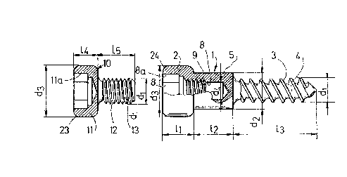
Figure 1 is side, partially cutout and partially perspective
a
view of the pin according to the invention;
Figure 2 is partially side view and partially perspective
a
view of a cap screw associated with the pin of Figure
1;
Figure 3 is front view of the pin of Figure 1;
a
Figure 4 is partially cutout and partially perspective view
a
of second embodiment of the pin; and
a
Figure 5 is cross sectional view of a jawbone with pins
a
inserted
therein.
DETAILED DESCRIPTION OF THE PREFERRED EMBODIMENT
Reviewing now the drawings, wherein like numerals
reflect like elements throughout the several views, Figures 1
and 3 depict pin 1, comprising bead 2 on its left end and
segment 4, on its right end, having external thread 3 to be
screwed into tissues, such as a jawbone. Thread 3
- 3 -

20~62~9~
has a profile which is particularly suited for being threaded into bone.
Between the external thread 3 carrying segment 4 and bead 2 is a smooth-
walled cylindrical segment 5. Cylindrical segment 5 has a diameter d2 which
is at least as large although preferably somewhat larger than diameter d~
of the external thread 3. Bead 2 contains dead end hole 8 which extends
from the left side of the bead 2 and pin 1 into the pin 1.
The hole 8 has an internal hexagonal surface 8a which
facilitates the insertion of a hexagonal screwdriver or similar rotational
tool whose dimensions conform to existing standards. The dead end hole 8
furthermore has an internal thread 9 (extending further internally from
hexagonal surface 8a) and is dimensioned to accommodate screw 10 (See
Figures 2, 5) until screw head 11 contacts bead 2.
Screw head 11 is configured to conform to the bead 2 and has
the same diameter d3 which is preferably identical to the diameter of the
bead 2. The diameter of threaded segment 13 is configured to allow for
adequate wall thickness in the region of the internal thread 9 of the pin 1
and to accommodate external thread 12. Although various dimensions for the
elements employed in the invention may be used, the following dimensions
have been shown to be effective and are deemed to be preferred for a
typical application, at this time:
d~ = diameter of the external threads 3
at pin 1 . . . . . . . . . . . . . . . . . . . . . . . . l.2mm
dz = diameter of the cylindrical segment . . . . . . . . . . 51.8mm
d3 = diameter of the bead 2 on the pin 1
and the diameter of the head 11 of
the screw 10 . . . . . . . . . . . . . . . . . . . . . . 2.5mm
d~ = diameter of the external thread 12
of the screw 10 . . . . . . . . . . . . . . . . . . . . . l.2mm
d4 = diameter of the portion of the dead
end hole 8 which has no thread . . . . . . . . . . . . . 1 mm
-4-

2os~~97
d5 = face spacing in the hexagonal hole
8a (see Figure 3a) . . . . . . . . . . . . . . . . . . 0.87mm
L~ = axi al 1 ength of the bead 2 . . . . . . . . . . . . . . . . 1. 5mm
L2 = axial length of the cylindrical
segment 4 . . . . . . 2 mm
L3 = axial length of the external thread
3 beari ng segment 5 . . . . . . . . . . . . . . . . . . . 2 mm
L4 = axial length of the screw head 11
(see Figure 2) . . . . . . . . . . . . . . . . . . . . . l.2mm
LS = axi al 1 ength of the screw 10 . . . . . . . . . . . . . , . 3 mm
Figure 4 is a partially cutout and partially perspective view
of a second embodiment of the pin of the invention. The pin 30, in this
embodiment, is similar in size and dimension to pin 1, except that the
axial length L4 of the cylindrical smooth-walled segment 32 is twice as
long as the corresponding segment 5 in the first embodiment. Of course,
longer or shorter segment pins may be used according to, for example, the
amount of tissue which must be grown to rebuild the bone to the desired
amount.
Additionally, the internal hole could be shaped for engagement
of a rotational tool or screwdriver having, for instance, a triangular,
square or five-cornered surface, rather than a hexagonal surface.
Furthermore, two radially extending slots could be provided on the edge 24
of the pin and also on the corresponding edge 23 of the screw 10 for
engagement of a conventional screwdriver.
Figure 5 cross-sectionally depicts typical use of the
invention. Two pins 1, 30 are threaded into the jawbone 41 to such a depth
that the entire carrying segment 4 of each pin is located inside the bone.
A tissue-friendly capping foil 42, preferably comprised of polytetrafluoro-
ethylene, is placed over these pins and fastened at the foil edge to the
jawbone with screws 43. Screws 10 are then threaded into pins 1 and 30 for
subsequently securing foil 42. Experience has shown that bone mass 44 will
-5-

2062~9~
begin to grow between the bone 41 and the foil 42 until the entire space
therebetween is filled. At that time, foil 42, screws 10, 43 and pins l,
30 may be removed to allow mucus membrane the opportunity again to grow
across the bone.
While the invention has been illustrated and described as
embodied in the auxiliary means for fastening a capping on bone tissue or
the like, it is not intended to be limited to the details shown, since
various modifications and structural changes may be made without departing
in any way from the spirit of the present invention.
-6-

Representative Drawing
A single figure which represents the drawing illustrating the invention.
Administrative Status

2024-08-01:As part of the Next Generation Patents (NGP) transition, the Canadian Patents Database (CPD) now contains a more detailed Event History, which replicates the Event Log of our new back-office solution.

Please note that "Inactive:" events refers to events no longer in use in our new back-office solution.

For a clearer understanding of the status of the application/patent presented on this page, the site Disclaimer , as well as the definitions for Patent , Event History , Maintenance Fee  and Payment History  should be consulted.

Event History

Description Date
Inactive: IPC from MCD 2006-03-11
Time Limit for Reversal Expired 2003-03-10
Letter Sent 2002-03-11
Grant by Issuance 1999-08-31
Inactive: Cover page published 1999-08-30
Inactive: Final fee received 1999-05-26
Pre-grant 1999-05-26
Notice of Allowance is Issued 1999-04-07
Letter Sent 1999-04-07
Inactive: Status info is complete as of Log entry date 1999-03-31
Inactive: Application prosecuted on TS as of Log entry date 1999-03-31
Inactive: IPC removed 1999-03-05
Inactive: First IPC assigned 1999-03-05
Inactive: IPC assigned 1999-03-05
Inactive: Approved for allowance (AFA) 1999-02-22
All Requirements for Examination Determined Compliant 1995-11-21
Request for Examination Requirements Determined Compliant 1995-11-21
Application Published (Open to Public Inspection) 1992-09-12

Abandonment History

There is no abandonment history.

Maintenance Fee

The last payment was received on 1999-03-08

Note : If the full payment has not been received on or before the date indicated, a further fee may be required which may be one of the following

  • the reinstatement fee;
  • the late payment fee; or
  • additional fee to reverse deemed expiry.

Please refer to the CIPO Patent Fees web page to see all current fee amounts.

Fee History

Fee Type Anniversary Year Due Date Paid Date
MF (application, 6th anniv.) - standard 06 1998-03-10 1998-02-13
MF (application, 7th anniv.) - standard 07 1999-03-10 1999-03-08
Final fee - standard 1999-05-26
MF (patent, 8th anniv.) - standard 2000-03-10 2000-02-24
MF (patent, 9th anniv.) - standard 2001-03-12 2001-02-15
Owners on Record

Note: Records showing the ownership history in alphabetical order.

Current Owners on Record
INSTITUT STRAUMANN AG
Past Owners on Record
DANIEL BUSER
FRANZ SUTTER
ULRICH MUNDWILER
Past Owners that do not appear in the "Owners on Record" listing will appear in other documentation within the application.
Documents

To view selected files, please enter reCAPTCHA code :


To view images, click a link in the Document Description column. To download the documents, select one or more checkboxes in the first column and then click the "Download Selected in PDF format (Zip Archive)" or the "Download Selected as Single PDF" button.

List of published and non-published patent-specific documents on the CPD .

If you have any difficulty accessing content, you can call the Client Service Centre at 1-866-997-1936 or send them an e-mail at CIPO Client Service Centre.


Document
Description 
Date
(yyyy-mm-dd) 
Number of pages   Size of Image (KB) 
Abstract 1993-12-14 1 19
Cover Page 1993-12-14 1 17
Claims 1993-12-14 4 83
Drawings 1993-12-14 1 35
Description 1993-12-14 5 160
Description 1999-02-10 6 219
Abstract 1999-02-10 1 19
Claims 1999-02-10 2 56
Cover Page 1999-08-24 1 37
Representative drawing 1999-04-30 1 8
Representative drawing 1999-08-24 1 12
Commissioner's Notice - Application Found Allowable 1999-04-07 1 164
Maintenance Fee Notice 2002-04-08 1 179
Correspondence 1999-05-26 1 52
Fees 1997-03-05 1 53
Fees 1996-03-05 1 50
Fees 1995-03-09 1 53
Fees 1994-03-07 1 37
Prosecution correspondence 1996-01-31 2 52
Examiner Requisition 1997-12-09 1 34
Prosecution correspondence 1998-04-09 3 68
Courtesy - Office Letter 1995-12-14 1 52
Prosecution correspondence 1995-11-22 1 45