Note: Descriptions are shown in the official language in which they were submitted.
W091/19106 ~ ~ 2 ~ 7 8 PCT/US90/04680
Description
PILOT CONTROL CIRCUIT FOR LOAD SENSING
HYDRAULIC SYSTEMS
Technical Field
This inv~ntion relates qenerally to a load
sensing hydraulic system and more particularly to a
pilot control circuit incorporated within the load
sensing system.
Backaround Art ..
The load sensing variable displacement pum~
of a load sensing hydraulic system usually has a
15 pressure responsive displacement controller which
automatically àdjusts pump output to meet flow and
pressure demands of the system. If none of the
hydraulic motors of the hydraulic systems are being
operated in a manner to generate a load pressure
signal for transmission to the displacement
.- contr~ller, the output of the pump is reduced to a
minimum level cufficient to maintain the system
pressure at a relatively low margin pressure. The
hydraulic motors of many such load sensing systems are
controlled by a pilot operated control valve which is
moved to an operating position by directing . '.
. . pressurized pilot fluid to the appropriate end of the
: -control valve.through a'manually operated pilot
. control valve..i.Since the margin pressure is normally
30,. at a:sufficient:level~to:support pilot actuation of
~ the.pilot operated control valves, the pilot~circuit
of some of those systems utilize~the load sensing
. variable displacement pump-as,a source-of:pressurized
pilot~:~luid.,. To prevent.over-pressurization of the
pilot ~y~tem, a pressure reducing.valve ~is commonly
~ .
, . .
-, . . ,. . . :
. . .~
; . . : . ~ - . . ~
. . . . . . . . . . .
- . .. . . .
WO 91/19106 2 ~ 7 ~ PCT/US90/04680
-2-
provided in the pilot circuit to maintain the pressure
of the pilot circuit at a level slightly less than the
margin pressure of the main system.
one of the problems encountered with such
systems occurs when a pilot operated directional
control valve is moved to a position sufficient to
allow a load supported by a hydraulic m~tor to
. freefall such that the side of the motor receiving
fluid from the directional control valve tends to
lo cavitate. During a freefall condition, the flow
requirements to fill the expanding or intake side of
the motor is usually greater than the output.capacity
of the pump even though the pump strokes to its
maximum displacement setting. Thus the intake side of
the motor.tends to cavitate and since the main supply
conduit from the pump is connected with the cavitated
side .of the motor through the control valve, the main
system pressure drops below the pressure level of the
pilot circuit. Consequently, the pressure level of
the pilot circuit drops allowing the control valve to
.. .move back to its neutral position prematurely stopping
the lowering of the load.
...The present invention is directed to overcoming
! ~one or more of the above problems.
Disclosure o~.~he Invention
,, J~ :_., In:one~aspect of the present:invention, a
..pilot control circuit is provided for a load.sensing
;hydraulic system which has a hydraulic motor, a load
:,.sensing variable~displacement pump, a supply conduit
r~ : connected to the-pump, and a pilot operated valve
connected to.the suppiy conduit and to the hydraulic
.motor:and being.moveable to a position at-which the
supply.conduit communicates with the motor.-...The pilot
35 .~control circuit comprises a pilot control valve
~- . . ~-
. .
- . - -
WO91/19106 ~ 8 PCT/US90/04680
::
--3--
connected to the pilot operated valve, a primary pilot
line connected to the supply conduit, a secondary
pilot line connected to the pilot control valve, a
pressure reducing valve connected to the primary and
secondary pilot lines and adapted to reduce the
pressure of the fluid passing therethrough from the
primary pilot line to the secondary pilot line to a
predetermined level and accumulator means connected to
the secondary pilot line for storing pressurized piIot
lo fluid for use by the pilot control circuit to maintain
the pilot operated valve in the operating position
when the fluid pressure level in the supply co~duit
momentarily drops to a level lower than said
predetermined level.
The present invention provides a pilot
control circuit which is connected to..a main supply
conduit of a load sensing hydraulic system through a
reducing valve and thereby utilizes the load sensing
variable displacement pump as the source of
~ 20 pressurized pilot fluid. The pilot circuit includes ..
an accumulator connected to a pilot line downstream of
the pressure reducing valve for storing fluid which
: can be used for the pilot circuit under conditions
wherein the pressure in the main supply conduit is
momentarily insufficient to maintain the pilot
operated valve in an actuated condition.
. . . , -
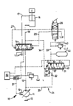
Briçf Description of ~he Drawings - : :
. . The sole-fiaure is a schematic illustration
:of an embodiment of the present invention.:.
- ;.
Best Mode for Carryina Out the Invention
.. A load ~ensing hydraulic 6ystem 10 includes
.a load sensing..variable.displacement pump 11 connected
.: -.; : .
:
.
. , - . . -
-- ~ , - . .: : -
.~ . . . - : ~
WO91/19106 ,,~ PCT/US90/04680
-4- :
. . ~
- to a tank 12, a supply conduit 13 connected to the
pump, a pilot operated directional control valve 14
connected to the supply conduit 13 and to the tank 12,
and a load supporting hydraulic motor 16 connected to
the directional control valve 14 through a pair of
motor conduits 17,18. The pump 11 has a displacement
controller 19 for automatically adjusting the pump
output to meet the flow and pressure demands of the
system. A load pressure signal network 21 is
connected to the displacement controller 19 and to the
directional control valve 14. Another work system 22
is connected to the supply conduit 13 and to the
signal network 21 in the usual manner. . . ..
A pilot controi circuit 24 includes a
manually actuated pilot control valve 26 connected to
opposite ends of the directional control valve 14
through a pair of pilot lines 27,28. A primary pilot
line 29 is connected to the supply conduit 13 and to a
- combined selector and pressure reducing valve 31
through a check valve 32. A secondary pilot line 33
connects the pressure reducing valve 31 to both the
: pilot control valve 26 and the work system 22. A load
pressure pilot line 34 is connected to the motor line
18 and to the pressure reducing valve 31 through a
check valve 36. The pressure reducing valve 31 has
primary and secondary flow paths 37,38 therethrough
and opposite ends 39,40 and is urged to the position
shown by a spring 39.disposed at the end 39. The
.. ;-secondary pilot line 33 is connected~.to the end 40.
An accumulator~42~and a relief valve 43 are connected
to the secondary pilot line downstream from the
pressure reducing valve.-
. The pressure reducing valve 31 is moveablebetween three basic infinitely variable ranges of
35 operating positions indicated by the letters A, B, and ..
: .
,
WO91/19106 ~ ~2 `~ 7 ~ PCT/US90/04680
c. At the A position of the reducing valve, the
primary and secondary flow paths 37,38 are both in
communication with the pilot line 33. At the B
position, the primary flow p~th 37 is in communication
with the pilot line 33 and the secondary flow path 38
is blocked therefrom. At the C position of the
reducing valve, the primary and secondary flow paths
37,38 are both blocked from the pilot line 33.
10 Industrial Applical:~ilitv
The directional control valve 14 is moveable
from the neutral position shown to first and second
infinitely variable operating positions. At the .
neutral position, the supply conduit 13 and motor
lines 17,18 are isolated from each other, while the
signal network 21 is vented to the tank 12. ~ightward
movement of the directional control valve 14 to the
: first operating position communicates the motor
conduit 17 with the supply conduit 13 and the signal
network 21 while the motor conduit 18 is communicated
with the tank 12. Similarly, leftward movement of the
; . directional control valve to the second operati~g
~ position communicates the motor conduit 18 with the
: supply conduit 13 and the signal network 21 while the
motor conduit 17 is co~municated with the tank 12.
When the directional control valve 14 is in the
neutral position shown, no load pressure signal is
. being directed to the displacement controller 19 and
the displacement of the pump automatically adjusts to
;a position to maintain a ~ubstantially low margin
~ prQssure in the supply conduit 13. In this
: embodiment, the margin pressure is approximately
2000 kPa. ~.- ;- ` -- - . :
- .The pressurized fluid in the supply conduit
13 passes through the pilot line 29, the check valve
, ..... . . .. . . .
:~ ~ . . - . :. . . - - . ~
: ..... , . .. , - - .. .-~ . . .
. , , - . - - - :
- . . . . . .
WO91/19106 '~ ~ 2 7 7 ~ PCT/VS90/04680
-6-
32, the primary flow path 37 of the pressure reduci~g
valve 31 and into ~he pilot line 33. The pressurized
fluid in the pilot line 33 exerts a force on the end
40 of the pressure reducing valve 31 moving it
leftwardly against the sprin~ 39 generally to the B
position. More specifically, the reducing valve will
oscillate somewhat between the B and C positions to
controllably modulate or meter fluid flow through the
primary flow path 37 to reduce the pressure of the
fluid passing therethrough to the pilot line 33 to a
predetermined pressure level which in this embodiment
is about 1800 kPa. Pressurized fluid in the piiot
line 33 enters the accumulator 42 and is stored
therein ~t the 1800 kPa level. '
To extend the hydraulic motor 16, the
operator moves the pilot control valve 26 downwardly
; to direct pressurized fluid from the pilot line 33
through the pilot line 28 moving the pilot operated
directional control valve 14 left~ardly to the second
operating position. At such position, pressurized
fluid in the supply conduit 13 passes through the
; directional control valve and motor conduit 18 to the
hydraulic motor 16. The load pressure in the motor
line 18 i6 transmitted through the directional control
valve and the signal network 21 to the displacement
controller l9 to change the displacement of the pump
ll to generate sufficient fluid flow and pressure to
meet the demand required to extend the hydraulic motor
16. - i -
- - ,; To retract the hydraulic motor 16, the
operator moves the pilot control valve 26 upwardly to
direct pressurlzed pilot fluid from the pilot line 33
; through the pilot line 27 moving the directional
control valve 14 rightwardly to its first operating
35 . - po8it$0n. If the control valv- 14 is moved
: . . - . . . . . .
, ~ . , , : ' . : ' '
.
WO 91/19106 ~ ~$ ~ ~ 7 ~ ~ PCT/US90/04680
-7-
sufficiently rightwardly, the load supported by the
hydraulic motor 16 tends to freefall. When this
happens, the expanding side of the hydraulic motor
tends to cavitate and momentarily causes a drastic
reduction in the fluid pressure in the motor conduit
17 and the supply con~uit 13 to a pressure level lower
than the predetermined pressure level of the fluid in
the secondary pilot line 33 even thou the displacement
controller 19 causes the pump to go to its maximum
displacement setting in an attempt to maintain the
output pressure at the min~mum margin pressure. Under
this condition, the check valve 32 prevents reverse-
flow of pilot fluid through the primary pilot line 2g
such that the pressurized fluid stored in the
accumulator 42 becomes available for use by the pilot
control circuit lO to maintain the directional control
valve 14 in its actuated position. The pressurized
fluid from the accumulator is also available for use
by the pilot control of the work system 22.
The capacity and the pressure rating of the
accu~ylator is chosen to provide a sufficient supply
of pilot fluid at a pressure level to maintain the
~ directional control valve 14 in its actuated position
during the period of time that the pressure level in
the supply conduit 13 is momentarily lower than the`
pressure level in the pilot line 33. In this
embodiment such period of time is'about the amount of
time that the hydraulic'motor is'in the~freefall
condition. -';' ' ~' ' ~' ' ''
;~ The load pressure pilot line 34`provides a
backup~6upply of pressurized fluid to the pilot
circuit 24 in-~ituations where the pump is not
operating. Under that~'condition,' the'load generated
pressure in the motor conduit 18 can pass through the
load pressure pilot line 34, the check valve 36, and
. . . . . - .................... . ........... - .-
- . - . . .
.:`~ . ' .. ' ' ,. : .. : .... ', : :
WO91/19106 æ~ ~2~ 3 PCT/US90/04680
--8--
the secondary flow path 38 of the pressure reducing
valve and into the pilot line 33 where it acts on the
end 40 of the pressure reducing valve. The pressure
reducing valve will remain basically in the A
position, but will oscillate somewhat between the A
and B positions to controllably meter the fluid flow
through the secondary flow path to reduce the pressure
of the fluid passing throu~h the secondary flow path
similarly to that described above. The fluid passing
through the pressure reducing valve under this
condition can thus be utilized by the pilot control ,
valve 26 to move the directional control valve
rightwardly to connect the motor conduit 18 to the
reservoir 12 for lowering the load. Although the
primary flow path remains in,communication with the
pilot line 33, reverse flow therethrough'is blocked by
the check valve 32.
In view of the foregoing, it is readily
apparent that the structure of the present invention
~ 20 provides an improved pilot control circuit for a load
', sensing hydraulic system wherein the control valves
are maintained in an actuated position even though the -
main system pressure momentarily drops below a level
6ufficient to support pilot operation. This is
accomplished by connecting an a¢cumulator to the pilot
line for 6toring pressurized fluid which can then be
u6ed to maintain a pilot operated control valve in an
actuated condition regardless of the pressure level
existing in the main system. Moreover, the pilot
,control circuit,~is,also connected in a manner that
enables it to use load generated pressure as the
source of pilot pressure for lowering a load even when
,,the main 6ystem pump is not operating. , ,, - -
,, . ~ . . ~ , . .
~ 35~
.'~' ' ~
:,
, ~ . ,
. .
., . ,~ . .
: . : . - ,: . . .
,: . : . - - -
- . : , .- : -
WO91/19106 ~ ~ 2 7 7 ~ PCT/US90/04680
_9_
Other aspects, objects, and advantages of
this invention can be obtained from a study of the
drawing, the disclosure, and the appended claims.
. . .
.
2S
.
... .
.. , ; .
,: . . . ~ . ,, :
` -
.: ' '
:,, -
. . .
: 35
.
: ~-; ~ : - - - ...... . . . . . .. . .. . . - . . . . . - .
- ,.
.
.
. - :
- :