Language selection

Search

Patent 2062821 Summary

Third-party information liability

Some of the information on this Web page has been provided by external sources. The Government of Canada is not responsible for the accuracy, reliability or currency of the information supplied by external sources. Users wishing to rely upon this information should consult directly with the source of the information. Content provided by external sources is not subject to official languages, privacy and accessibility requirements.

Claims and Abstract availability

Any discrepancies in the text and image of the Claims and Abstract are due to differing posting times. Text of the Claims and Abstract are posted:

  • At the time the application is open to public inspection;
  • At the time of issue of the patent (grant).
(12) Patent: (11) CA 2062821
(54) English Title: PLUG ELEMENT FOR ELECTRIC CONNECTION, IN PARTICULAR DISTRIBUTION BOARDS OR THE LIKE
(54) French Title: PRISE POUR TABLEAU DE DISTRIBUTION ET AUTRES USAGES ASSIMILES
Status: Expired and beyond the Period of Reversal
Bibliographic Data
(51) International Patent Classification (IPC):
  • H01R 25/14 (2006.01)
(72) Inventors :
  • BOROS, FERENC (Germany)
  • HAAR, RAINER (Germany)
(73) Owners :
  • KLOCKNER-MOELLER GMBH
(71) Applicants :
  • KLOCKNER-MOELLER GMBH (Germany)
(74) Agent: SMART & BIGGAR LP
(74) Associate agent:
(45) Issued: 2000-11-07
(86) PCT Filing Date: 1991-04-17
(87) Open to Public Inspection: 1991-10-27
Examination requested: 1998-02-10
Availability of licence: N/A
Dedicated to the Public: N/A
(25) Language of filing: English

Patent Cooperation Treaty (PCT): Yes
(86) PCT Filing Number: PCT/EP1991/000729
(87) International Publication Number: WO 1991016743
(85) National Entry: 1991-12-24

(30) Application Priority Data:
Application No. Country/Territory Date
P 40 13 311.7 (Germany) 1990-04-26

Abstracts

English Abstract


The contact properties of plug elements deteriorate even with slight twists.
By using elastic intermediate,
current-transmitting elements, a relative insensitivity to twists is obtained.
In order to reliably
secure the intermediate elements to bearing or current-carrying-off elements,
however high costs are incurred.
In order to eliminate the disadvantages of the state of the art and to obtain
good contact properties
with a reliable fastening, the contact bars are imbedded in a plug shell in
such a way that they
are located in window-like openings and engage slots by their edges. The
current is led by contact tabs
that protrude from the plug shell. The plug shell in composed of two identical
halves which may be
interconnected by interlocking and by adherence without any additional
fastening elements. With these
plug elements, a reliable contact of busbars is easily obtained and it becomes
possible to supply with
load current plug-in racks of distribution boards with plug-in racks and
reduced plugging forces.
Besides other advantages, this plug element is rugged and easy to mount.


Claims

Note: Claims are shown in the official language in which they were submitted.

8
Claims
Plug element for an electrical connection, in particular of
switchgear with C-shaped bus bars, bus bars with slot-like
tap zones, or socket elements in distribution installations,
preferably in withdrawable unit distribution boards or
panels, consisting of a mounting element and elastic contact
elements for current transmission, characterized by the fact
that the plug element (1) consists of a plug shell (2), a
contact strip (4) and contact lamination strips (6a, 6b),
whereby the contact lamination strips (6a, 6b) are embedded
in window-like openings (10a, 10b) of the plug shell (2),
and are held by the latter, so that they act as elastic
current bridges between the bus bar or the socket element
and the contact strip (4) carrying the current.
Plug element accord-ing to Claim 1, characterized by the fact
that the plug shell (2) is made of insulating material.
Plug element according to Claim 1, characterized by the fact
that the plug shell (2) is made of metal.
Plug element according to one of the Claims 1 to 3,
characterized by the fact that the plug shell (2) consists
of two identical plug shell halves (3a, 3b) which, when
assembled on the flat sides, form window-like openings (10a,
10b) to hold contact lamination strips, and have a closed
plug front wall on their end surface (17), and have an
opening (34) on their rear side (16) for the contact strip
(4) carrying the outgoing current.

9
5. Plug element according to one of the claims 1 to 4,
characterized by the fact that the plug shell halves (3a,
3b) are positively connected and form-fitted together
without additional fastening means.
6. Plug element according to one of the Claims 1 to 5,
characterized by the fact that the contact strip (4)
consists of two identical, symmetrically oriented contact
strip halves (5a, 5b) designed as punched parts, which are
shaped so that on one hand they contact the inside of the
contact lamination strips (6a, 6b), and on the other hand,
are combined closely together toward the back side (16) of
the plug element (1), and are brought out of the plug shell
(2) for the connection of an outgoing line (24).
7. Plug element according to one of the Claims 1 to 6,
characterized by the fact that the inner surfaces of the
plug shell halves (3a, 3b) in the end region (12), have a
dovetail guide groove (13a, 13b) running perpendicular to
the cover plate (8a, 8b), which groove makes the transition
into a likewise dovetail guide segment (14a, 14b), the
length of which extends to approximately the middle of the
guide groove (13a, 13b), so that the two plug shell halves
(3a, 3b) can thereby be positively connected to form a
single plug shell (2).
8. Plug element according to one of the Claims 1 to 7,
characterized by the fact that in the rear area (11a, 11b)
of the shell wall (9a, 9b) of the plug shell half (3a, 3b),
there are pins (18a, 18b, 19a, 19b) which are engaged in
holes (20a, 20b, 21a, 21b) on the other plug shell half (3a,
3b), and thereby form an additional positive connection
between the two plug shell halves.

10
Plug element according to one of the Claims 1 to 8.
characterized by the fact that on the cover plate (8a, 8b)
of the plug shell halves (3a, 3b), in the vicinity of the
window-like openings (10a, 10b), there is a guide segment
(23a, 23b), against which the contact strip halves are
braced, whereby the contact strip halves (5a, 5b) are fixed
in the plug shell (2).
10. Plug element according to one of the Claims 1 to 9,
characterized by the fact that the contact lamination strips
(6a, 6b), with their inwardly tapering lateral fastening
edges (7a, 7b, 7c, 7d), are embedded in grooves (15a, 15b,
15c, 15d) on the edges of the window-like openings (10a,
10b) of the plug shell (2), and that the grooves (15a, 15b,
15c, 15d) have a half-arrow shaped contour which runs
perpendicular to the shell wall (9a, 9b).
11. Plug element according to one of the Claims 1 to 10,
characterized by the fact that the contact strip halves (5a,
5b), in the area coming out of the plug shell (2), are
provided with stepped cross section reductions (25, 26), so
that an outgoing line (24) can be connected to the narrow
strip segment (27) by means of crimping.
12. Plug element according to one of the Claims 1 to 11,
characterized by the fact that the plug shell (2) has an
introductory taper (32) on its end surface (17).
13. Plug element according to one of the Claims 1 to 12,
characterized by the fact in the rear area of the plug shell
(2), there are grooves (31a, 31b) running at right angles to
the bus bar (30), which hold the plug element (1) in a
fixture.

Description

Note: Descriptions are shown in the official language in which they were submitted.


N ~ ~ N
T7RT -TIMID-!1
P-lua element ror. an electrical connection. in. pari.icuiar: iru ...,
distribution boards or similar installations
This invention relates to a plug element for an electrical
connection, in particular for the electrical connection of
switchgear with bus bars or socket elements in distribution
boards or units, preferably in withdrawable distribution units,
as indicated in the generic portion of Claim 1.
Contact systems of the prior art have, perpendicular to the plug
or fastening plane, flexible contact tabs or contact segments of
a known type, which make contact with the bars carrying the
current. Such a contact system is disclosed in DE 26 47 573, in
which a spring tab is folded around a leaf-shaped segment, and is
equipped with.a coil spring, which is in contact with the inside
of the tab and presses it outward, whereby the outer sides of the
tab, under pressure from the spring, come into contact with the
contact surfaces of two rectangular-shaped bus bars running
parallel to them. Such contact systems are relatively sensitive
to warping or twisting.
The plug-in contact disclosed in EP 0 086 316 represents another
contact system.
This plug-in contact consists of two interacting contact wires,
which are held in a U-profile by a leaf spring. The contact
surface is formed .by a center contact tab of the first contact
wire, and two side contact tabs of the second contact wixe, one
on either side of the center contact tab. The intended purpose
of his complex design is to make the system relatively
insensitive to warping or twisting.

i ~0 n '
i ~ ~ ~ M
NHL-KMO-04
-U~ ~~.r." .~' . ' '~"'~ .'.:?rwi~~ri~nal ['nnt~tc:i...SVSi.C.W. . ~'n i.iW T.
......
-VJ JG -!i.i vvh uiSC~v..a..-... ~ --. -- -
case, plug elements are provided with U-shaped springs, which
counteract the expansion of locator slots located on the plug
elements.
These plug elements are provided with sleeves to hold the cable
ends. However, they are not suitable for making contact with C-
shaped bus bars or bus bars with slot-shaped tap zones.
DE 31 26 306 also discloses contact units which contain a cage-
like housing and several pairs of contact laminations. Each
contact lamination is subject to the action of a leaf spring.
Such contact units have the same disadvantage as the contact
system disclosed in. DE-OS 32 43 064.
The prior art also includes plug systems which have contact
laminations. Such contact laminations, as described in the BBC
publication "Konstrukteur" 5/69, Page 185, have lamination
segments which: fit relatively well with the contact surfaces,
even if the latter do not run completely parallel.

>:~ Jc~:
~~~~p~i
NHT,-KMC1-Qd -
-mho .~,~ja_Ct pF-._t t'1 P_ 111V211tlOn 1S t0 Create 3 ~.7lt,ll~ ClCSI~CII.L.
i'vi_ .,
electrical connection which has good contact characteristics,
consists of simple parts, can be manufactured economically, is
easy to assemble and install, arid is also suitable for the
electrical connection of C-shaped bus bars or bus bars with slot-
shaped tap zones.
This object is achieved by the invention having the
characteristics indicated in Claim 1. As a result.of the
invention, in spite of the use of contact lamination strips, the
use of a plug-in connector, which is generally complex and
expensive to manufacture, is no longer necessary. However, the
good contact characteristics of contact laminations are retained,
even when there is a slight warping, twisting or rotation of the
plug element.
It is particularly advantageous to make the plug shell of
thermoplast or thermosetting plastic, and the contact strip as a
punched part, whereby the plug shell and the contact strip are
each composed of two identical halves.
The features indicated in Claims 7 and 8 produce an additional
advantageous realization of the invention. As a result of these
features, there is a strong and secure connection of the two
shell halves, and the plug element is particularly easy to
assemble and install as a result of the use of a screw-less
connection.
Claims 7 to l3 disclose particularly advantageous refinements of
the invention:
A particular advantage of the refinement disclosed in Claim 10 is
that the half-arrow shaped contour, during installation, makes
possible a locking of the contact lamination strips from the
inside of the plug shell out:

~iju~t~N.~
TTTIT -VMIV1 ~ l1 il
a" ad.z,antaga_o;.ls .feature of Claim ~l is tnac t'Iie_ plug_ e:~erneric, ..
while being plugged into a C-shaped bus bar, a bus bar with
slotted tap zones or a jack element, is securely guided into the
slot in the bar.
One preferred embodiment of the invention is schematically
illustrated in the accompanying drawings.
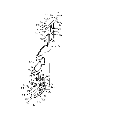
Figure 1 shows a plug element for the electrical connection of
switchgear with C-shaped bus bars, shown disassembled
and in a perspective view,
Figure 2 shows a perspective view of the plug element,
assembled,
Figure 3 shows a cross section of the plug element engaged with
a C-shaped bus bar, and
Figure 4 shows an enlarged detail of the plug element
illustrated in Figure 3, whereby the half-arrow shaped
grooves are clearly visible
The plug element 1 shown in the drawing is used for the
electrical connection of switchgear or similar devices to a C-
shaped bus bar or a socket element in distribution boards or
panels.
As shown in Figures 1 and 2, the plug element consists of a plug
shell 2, which consists of two identical plug shell halves 3a,
3b, a contact strip 4 with two identical contact strip halves 5a,
5b, and two symmetrical and parallel contact lamination strips
6a, 6b,. each with two tapered fastening edges 7a, 7b, 7c, 7d on
the side.
The~plug shell halves 3a, 3b are made of a thermoplast or a
thermosetting plastic, and each consists of a cover plate 8a, 8b,
and a shell wall 9a, 9b molded at a right angle. Each shell

iv niu-1v1'1V- V4
A,°,' o,,~, --y.: dlV~'a°'7 .'..::~0 tt.jp Znr,cc 11 a 1 i ~,~
'l-~~-,- °l~b;...g~ tl'ldt
iv a
when the plug shell 2 is assembled, window-like openings 10a, lOb
are formed.
The plug shell halves could also be made of metal, e.g. employing
a die casting process. The plug shell halves are designed so
that they can be connected by means of a positive and form
fitting connection, without any additional fastening means.
Perpendicular to the cover plate 8a, 8b, the end zones 12a, 12b
have a dovetail guide groove 13a, 13b, which makes the transition
into a likewise dovetail guide segment 14a, which extends
lengthwise to approximately the center of the guide groove 13a,
13b, and penetrates the identically-shaped guide groove 13a, 13b .
of the other half 3a, 3b of the plug shell by insertion into an
introductory taper 22a, 22b, and thus achieves a positive and
form fitting connection of the two plug shell halves 3a, 3b into
a single plug shell 1.
An additional form-fitting connection is achieved, in that in the
rear zone lla, ilb of the shell wall 9a, 9b, there are pins 18a,
18b, 19a, 19b designed so that they are engaged in holes 20a,
ZOb, 21a, 21b located on the cover plate 8a, 8b of the other half
of'the plug shell 3a, 3b:
The contact lamination strips 6a, 6b are embedded with their
inwardly tapering lateral fastening edges 7a, 7b, 7c, 7d'in
grooves 15a, 15b, 15c, 15d of,the plug shell 2, adjacent to the
edges of the-window-like openings 10a, lOb, so that the contact
lamination strips 6a; 6b fill up the entire surface of the
window-like openings 10a; lOb. These grooves 15a, 15b, 15c, 15d
have a continuous half-arrow shaped contour running perpendicular
to the shell wall 9a, 9b, which makes possible an introduction
(in the groove direction (Arrow A)) or locking (from the inside

~~~~Uro.~
(? ~yfl~-'t1"-nifl-yl
~OT LIl-~' DlllCl S(lell G ~OL1G ~(NI-i."OW tSl ) OL ~Clle ~COnLaC-C iamWB~lon
strips 6a, 6b before the assembly of the plug shell 2.
As also shown in Figure 1, molded onto the cover plate 8a, 8b of
each plug shell half 3a, 3b, in the vicinity of the window-like
openings 10a, lOb, is a guide segment 23a, 23b which fixes the
contact strip halves 5a, 5b in the plug shell 2.
The contact strip halves 5a, 5b are designed as a punched part,
and are shaped so that they are braced against the guide segment
23a, 23b in the zone facing the end surface 17 of'the plug
element 1, and are in contact with the inside of the contact
lamination strips 6a, 6b.
The contact strip halves 5a, 5b are joined closely together
toward the rear side 16 of the plug shell 2, as shown in
particular in Figure 2, and are designed for the electrical and
mechanical connection of an outgoing line 24 from the plug shell
2. They are also provided with stepped, reduced cross sections
25, 26, so that crimping technology can be used to connect an
outgoing line 24 to the narrow strip segment 27, whereby the-
center strip segment 28 forms a stop for the ferrule 29.
On the cover plates 8a, 8b of each plug shell half 3a, 3b,
running at right angles to the bus bar 30, there are rectangular
grooves 31a, 31b, which are used to.fasten the plug element 1 in
a fixture on the reverse side of a withdrawable distributor panel
unit.

n 4
N
i~ri~~-~~G-Gu
mu. 7.~,.. ~y'..,'...t 'I ~ ~S °::v.. S'.:"~.~.uC° 1'7
.1..~.Y..r..-~wA-r.nra~.:C~'J'"~r
m2 i.~...7 ... ..~ .. y, C.~. ~ ~ , -1
taper 32, so that when the plug element 1 is inserted into the C-
shaped bus bar 30, it is securely guided into the bar slot 33, to
once again guarantee good electrical contact between the contact
lamination strips 6a, 6b and the bus bar 30.
Figure 3 shows the plug element 1 in the plugged-in state, and
shows how the contact lamination strips 6a, 6b form an
intermediate layer and cuxrent bridge between the contact strip
halves 5a, 5b and the C-shaped bus bar 30.
Figure 4 shows an enlarged detail. It shows how the contact
lamination strips 6a, 6b are embedded in the half-arrow shaped
grooves 15a, 15b, 15c, 15d and are prevented from falling out.

Representative Drawing
A single figure which represents the drawing illustrating the invention.
Administrative Status

2024-08-01:As part of the Next Generation Patents (NGP) transition, the Canadian Patents Database (CPD) now contains a more detailed Event History, which replicates the Event Log of our new back-office solution.

Please note that "Inactive:" events refers to events no longer in use in our new back-office solution.

For a clearer understanding of the status of the application/patent presented on this page, the site Disclaimer , as well as the definitions for Patent , Event History , Maintenance Fee  and Payment History  should be consulted.

Event History

Description Date
Time Limit for Reversal Expired 2004-04-19
Letter Sent 2003-04-17
Grant by Issuance 2000-11-07
Inactive: Cover page published 2000-11-06
Inactive: Final fee received 2000-08-10
Pre-grant 2000-08-10
Notice of Allowance is Issued 2000-04-05
Letter Sent 2000-04-05
Notice of Allowance is Issued 2000-04-05
Inactive: Approved for allowance (AFA) 2000-02-29
Amendment Received - Voluntary Amendment 1998-09-10
Inactive: RFE acknowledged - Prior art enquiry 1998-03-30
Inactive: Status info is complete as of Log entry date 1998-03-30
Inactive: Application prosecuted on TS as of Log entry date 1998-03-30
All Requirements for Examination Determined Compliant 1998-02-10
Request for Examination Requirements Determined Compliant 1998-02-10
Deemed Abandoned - Failure to Respond to Maintenance Fee Notice 1997-04-17
Inactive: Adhoc Request Documented 1997-04-17
Application Published (Open to Public Inspection) 1991-10-27

Abandonment History

Abandonment Date Reason Reinstatement Date
1997-04-17

Maintenance Fee

The last payment was received on 2000-04-11

Note : If the full payment has not been received on or before the date indicated, a further fee may be required which may be one of the following

  • the reinstatement fee;
  • the late payment fee; or
  • additional fee to reverse deemed expiry.

Please refer to the CIPO Patent Fees web page to see all current fee amounts.

Fee History

Fee Type Anniversary Year Due Date Paid Date
Request for examination - standard 1998-02-10
MF (application, 7th anniv.) - standard 07 1998-04-17 1998-04-09
MF (application, 8th anniv.) - standard 08 1999-04-19 1999-04-14
MF (application, 9th anniv.) - standard 09 2000-04-17 2000-04-11
Final fee - standard 2000-08-10
MF (patent, 10th anniv.) - standard 2001-04-17 2001-04-10
MF (patent, 11th anniv.) - standard 2002-04-17 2002-04-16
Owners on Record

Note: Records showing the ownership history in alphabetical order.

Current Owners on Record
KLOCKNER-MOELLER GMBH
Past Owners on Record
FERENC BOROS
RAINER HAAR
Past Owners that do not appear in the "Owners on Record" listing will appear in other documentation within the application.
Documents

To view selected files, please enter reCAPTCHA code :


To view images, click a link in the Document Description column. To download the documents, select one or more checkboxes in the first column and then click the "Download Selected in PDF format (Zip Archive)" or the "Download Selected as Single PDF" button.

List of published and non-published patent-specific documents on the CPD .

If you have any difficulty accessing content, you can call the Client Service Centre at 1-866-997-1936 or send them an e-mail at CIPO Client Service Centre.


Document
Description 
Date
(yyyy-mm-dd) 
Number of pages   Size of Image (KB) 
Abstract 1995-08-08 1 93
Claims 1994-03-05 3 109
Drawings 1994-03-05 3 40
Description 1994-03-05 7 265
Cover Page 1994-03-05 1 15
Cover Page 2000-10-17 2 51
Representative drawing 2000-10-17 1 8
Representative drawing 1999-02-10 1 3
Reminder - Request for Examination 1997-12-18 1 117
Acknowledgement of Request for Examination 1998-03-30 1 173
Commissioner's Notice - Application Found Allowable 2000-04-05 1 164
Maintenance Fee Notice 2003-05-15 1 174
PCT 1991-12-24 12 415
Correspondence 2000-08-10 1 38
Fees 2001-04-10 1 33
Fees 2000-04-11 1 51
Fees 2002-04-16 1 33
Fees 1998-04-09 1 60
Fees 1999-04-14 1 51
Fees 1997-04-17 1 49
Fees 1996-03-14 1 50
Fees 1995-03-17 1 45
Fees 1994-03-07 1 32
Fees 1993-03-16 1 38