Language selection

Search

Patent 2062823 Summary

Third-party information liability

Some of the information on this Web page has been provided by external sources. The Government of Canada is not responsible for the accuracy, reliability or currency of the information supplied by external sources. Users wishing to rely upon this information should consult directly with the source of the information. Content provided by external sources is not subject to official languages, privacy and accessibility requirements.

Claims and Abstract availability

Any discrepancies in the text and image of the Claims and Abstract are due to differing posting times. Text of the Claims and Abstract are posted:

  • At the time the application is open to public inspection;
  • At the time of issue of the patent (grant).
(12) Patent Application: (11) CA 2062823
(54) English Title: DEVICE FOR CONNECTING CONTROL CURRENT LINES
(54) French Title: DISPOSITIF DE RACCORDEMENT DE LIGNES DE COMMANDE
Status: Deemed Abandoned and Beyond the Period of Reinstatement - Pending Response to Notice of Disregarded Communication
Bibliographic Data
(51) International Patent Classification (IPC):
  • H01R 13/703 (2006.01)
  • H02B 01/36 (2006.01)
(72) Inventors :
  • HEINZ, JOACHIM (Germany)
  • WINKLER, JOHANNES (Germany)
(73) Owners :
  • KLOCKNER-MOELLER GMBH
(71) Applicants :
  • KLOCKNER-MOELLER GMBH (Germany)
(74) Agent: BERESKIN & PARR LLP/S.E.N.C.R.L.,S.R.L.
(74) Associate agent:
(45) Issued:
(86) PCT Filing Date: 1991-04-17
(87) Open to Public Inspection: 1991-10-31
Examination requested: 1998-04-02
Availability of licence: N/A
Dedicated to the Public: N/A
(25) Language of filing: English

Patent Cooperation Treaty (PCT): Yes
(86) PCT Filing Number: PCT/EP1991/000732
(87) International Publication Number: EP1991000732
(85) National Entry: 1991-12-24

(30) Application Priority Data:
Application No. Country/Territory Date
P 40 13 310.9 (Germany) 1990-04-26

Abstracts

English Abstract

2062823 9116742 PCTABS00008
A device is disclosed for connecting control current lines in low
voltage switchboard plants. The device should allow the control
current in a plug-in distribution board to be easily maintained
up to a test position of the rack and to be cut beyond this
position when the rack is drawn out. The device has two multipoint
plugs with plugs and sockets, of which the first is rigidly linked to
the rack and the other is movably mounted over a limited path on
two guiding pins the terminal cross-section of which is
enlarged. In the test position, they are locked-in by elastic elements,
ensuring complete contact between both multipoint plugs in this
position already, when the rack is inserted. A plurality of control
lines can be thus easily cabled with little attrition, in a
reduced space within a plug-in distribution board and a test position
can be reached by drawing out he rack.


Claims

Note: Claims are shown in the official language in which they were submitted.

7 NHL-KMO-03
Patent Claims
1. Apparatus for the connection of control current lines, in
particular for withdrawable units in low voltage switchgear,
consisting of connector elements and socket elements, which
are in contact in a first position (test position) of the
withdrawable unit, and maintain this connection up to a
second withdrawable unit position ("On" position),
characterized by the fact that the connector and socket
elements are located in two contact strips (5, 11), one of
which is fixed and stationary, while the other is designed
so that it can move over a limited distance.
2. Apparatus according to Claim 1, characterized by the fact
that the moving contact strip follows the path of movement
of the withdrawable unit, so that during insertion, before
reaching the "test" position, there is a catch (detent?), in
which the movable contact strip is held, and causes contact
between the connector and socket elements, that as the
withdrawable unit is moved further into the "on" position,
the connected contact strips are carried along with it, and
that during the movement of the withdrawable unit toward the
"disconnected" position, the movement of the movable contact
strips is limited after passing the "test" position and
before reaching the "disconnected" position, so that the two
contact strips (5, 11) are separated by a safe distance even
before reaching the "disconnected" position, whereby the
movable contact strip remains held in the original position
between the detent and the limit.
3. Apparatus according to Claim 1 or 2, characterized by the
fact that the movable contact strip (5) is located so that
it can be moved on a mounting element (2), preferably on two
guide pins (83), that the guide pins (3) have an expanded

8 NHL-KMO-03
cross section (g) which limits the movement of the movable
contact strip (5), and that on the mounting element (2)
there are spring elements (4), which cause a catching of the
movable contact strip (5).
4. Apparatus according to one of the Claims 1 to 3,
characterized by the fact that on the mounting element (2),
there are spring elements (4), which have an offset (bend?)
in the direction of the contact strip (5), which is shaped
so that a first tapered surface (6), which lies in the
direction of the mounting element (2), has a slight slope,
while a second tapered surface (7) has a steeper slope, and
that the offsets are oriented so that together with the end
surfaces of the contact strip (5), they act as a catch
(detent?).
5. Apparatus according to one of the Claims 1 to 4,
characterized by the fact that the resilience of the spring
elements, when the withdrawable unit is being pulled out to
the test position, is designed so that the contact between
the moving contact strip and the contact strip fastened to
the rear wall of the withdrawable unit is not interrupted,
on account of the low slope of the tapered surface (6),
while when the withdrawable unit is pushed in from the
disconnected position into the test position, on account of
the slope of the second tapered surface (7), there is full
contact between the contact strips (5, 11).

Description

Note: Descriptions are shown in the official language in which they were submitted.


- ~T .--~M~--n ~
~nn~rat~ or the connec~:ion oï contrc~i ~;u~ i.les ~ ~ ~ ' `' J ~ --
This invention relates to an apparatus for the connection of
control current lines, in particular for withdrawable units in
low voltage switchgear.
Low voltage switchgear, such as motor control centers or power
distribution installations, have employed withdrawable unit
design for many years, in cases where it is necessary to be able
to quickly replace components assembled into a functional unit,
to achieve short down times for the electrical operating
equipment when maintenance work is required, or to achieve brief
operational interruptions caused by defective functional
components.
For testlng or maintenance purposes, it is currently customary to
insert or remove the withdrawable unit into or from a test
position, whereby only the load current is interrupted, and the
control current to the individual functional components is
continued in this position.
The continuation of the control current is achieved by contacting
the connecting elements which carry the control current even in
the test position.
If the withdrawable unit is pulled out farther, the control
current feed is also interrupted. This position is customarily
called the disconnected position.
The position in which both the load current and the control
current~are fed is called the "on" position.
,.
An apparatus of the type described above is disclosed in OS
2515152. ~n that case, the connecting elements are designed as
'.':' ' . : ' . .' ' ' : ' ' ' ' ,`
.:. . . . . . . .
:::: ' ' , . . . - ' '
.
. .. "' ' ': - ' ' '' ' . ' ~' ' ' ' . ' ~
.

~ r~ J.- r~r;u - ~J .
~li~i.,~ ~vll~, .~.~,._~ ~'~ ~ ^r.~ ~ ~ ~ ~ h, ~ ~ f ~ ~ t h ~ ~n
position to the test position.
In such a case, the connecting elements can suffer wear and
damaging abrasion on account of the sliding metal connecting
elements.
An additional contact apparatus which is also suitable for the
control current connection, is realized by means of a form-fit.
Such an apparatus is disclosed in OS 3114837.
The connection designated an overtravel contact consists of a
contact finger which is equipped with expanded portions for a
positive connection with a contact pin, whereby the connection is
released by means of a tripping sleeve.
This type of connection has the disadvantage that it is complex
and expensive, and takes up a relatively large amou~t of space.
It is therefore not well suited for a large number of control
lines.
The object of the invention is to create an apparatus for the
connection of control current lines, in particular for
withdrawable units in low voltage switchgear, employing simple
means which eliminate the disadvantages indicated above.
This object is achieved by the invention described in the
characteristic portion of Claim 1. The movable contact strip can
accompany the travel of the wi~hdrawable unit between the test
position and the "On" position, so that the control lines remain
connected for this distance.
-
:.

;~
3 ~ ~L-~Mu--u~
. .
l ne re L lne~n~n . v ~ V-2l1 ~,i VI ~ aA ~ i r`. C l ' i~ . i
advantageous for the accomplishment of the object indicated
above. In this refinement, the contact occurs automatically
during insertion, before reaching the test position, while during
extraction of the withdrawable unit, the disconnection from the
test position also occurs automatically.
That can be accomplished in particular by the use of spring
elements, which are characterized in Claims 3 and 4, to prevent
the movement of the movable contact strips by means of a catch
(detent?). It is particularly advantageous if the catch during
insertion is hard enough that the contact strips engage one
another, while during the extraction of the withdrawable unit,
they are not yet disconnected, but this disconnection
(separation?) from the disconnected position of the withdrawable
unit is caused by the limit of the guide pins.
The accompanying drawings contain a schematic illustration of one
preferred embodiment of the invention.
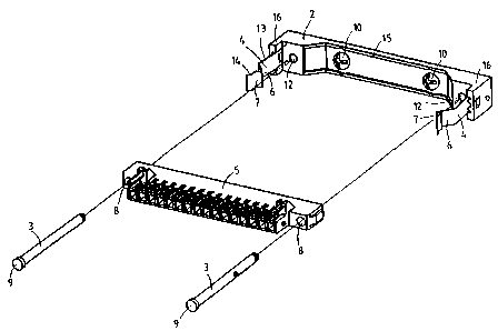
Figure 1 shows an disassembled view of the invention, in
perspective
- Fiqure 2 shows an assembled view of the invention, in
perspective
Fiqure 3 shows an overhead plan view of the apparatus in the
"On" position;
Figure 4 shows an overhead plan view of the apparatus in the
test position,
Figure S shows an overhead plan view of the apparatus in the
disconnected position.
' '
,, ' .
. .. . . .
.
. - ' ' ~ . , :
.

~ J i~
a ~ C '
appc,rG ~ . r2-r ~ 2~ ' n ~i~ur~ ~ and ~ iaure ~,
consists of a mounting element 2, two guide pins 3, two spring
tabs 4 and a contact strip 5 of the type disclosed by the prior
art. The mounting element 2 has an oblong shape, and is fastened
horizontally by means of two screws 10 in the vicinity of the
back side of the distribution board or distribution panel.
In each of its terminal sections, it has a spring tab 4
projecting toward the front.
Immediately next to the spring tabs, on the inside, are two
threaded holes to hold the two guide pins 3.
When the apparatus 1 is assembled, the contact strip S (here
designed as a socket connector) is mounted so that it can be
moved with the two guide pins 3 over a sliding seat in the
connection direction (Arrow A). The guide pins 3 thereby project
into and through the holes 8 in the side of the contact strip,
and are engaged with their end opposite the head in the threaded
holes 12 of the mounting element.
The head of the guide pin 3 has an expanded cross section 9, and
forms a stop for the contact strip 5.
The spring tab, starting at approximately one-half its length,
has a tab segment 6, which is tapered inward at an angle of
approximately 45 degrees, approximately to the guide pin.
Adjacent to this tab segment 6 is a tab segment 7, which is
tapered outward, and has an angle of approximately 90 degrees, so
that the latter runs practically parallel to the mounting
element.
' .

~28~3
~I~.L--Y~O-O-'
, ~. .
.ile ll,v~ IlllV,~ll l., in ~ ich ~.2. 2 ~ 2
for the lines exiting from the reverse side of the contact strip.
The contract strip 11 (here designed as a push-on terminal strip)
for the control current connection is permanently connected to
the withdrawable unit. In the "On" position, the withdrawable
unit is completely inserted, whereby the socket connector is also
inserted toward the rear and makes contact with the push-on
terminal strip, as shown in Figure 3.
In this position, both the load current and the control current
are fed to the equipment.
To move it into a test position, the withdrawable unit is pulled
out until the socket connector is a short distance ahead of the
stop which is formed by the head of the guide pin. To reach this
position, the socket connector is guided by the guide pins along ~
the connector direction (Arrow A).
During this process, the side segments of the socket connector
make contact with the tab segments 6 and push the spring tabs
outward, whereby the resilience of the tabs is designed so that
the contact between the socket connector and the push-on terminal
stri~p remains intact.
Once the socket connector has passed the tab segment 6, the
spring tabs fall back into the initial position. The
withdrawable unit has now been placed in the test position; the
load current was interrupted during extraction, so that now only
the;control current remains fed.
.
Figure 4 illustrates the test position.
. ~ .
~: . ~ ,::
~:~ ' , '
.
'
'~ .

2 n ~ n~
T~ ' ~ 0~l~ hc~ rl thc toct n~gi-tion- = - ^
the socket connector encounters a stop on the head of the guide
pin, so that contact is interrupted by further extraction, as a
result of the disconnection of the push-on terminal strip from
the socket connector. This position is illustrated in Figure 5,
and is conventionally called the disconnected position.
When the withdrawable unit i9 pushed back into the distribution
panel housing, the push-on terminal strip is once again engaged
in the socket connector, whereby the socket connector is held by
the tab segments 7, on account of their greater slope, until
complete contact is made. This position again corresponds to the
test position.
Finally, if the withdrawable unit is inserted even farther, the
tabs yield on account of the increasing force exerted on them,
and flex outward away from one another, so that the withdrawable -
unit can be placed in the "On" position.
. ~ .
~ :
; ~ ~
:; : : ~: :
: ~
. i . : .. : : ' ' ' '
.. : .- .
: . ,

Representative Drawing
A single figure which represents the drawing illustrating the invention.
Administrative Status

2024-08-01:As part of the Next Generation Patents (NGP) transition, the Canadian Patents Database (CPD) now contains a more detailed Event History, which replicates the Event Log of our new back-office solution.

Please note that "Inactive:" events refers to events no longer in use in our new back-office solution.

For a clearer understanding of the status of the application/patent presented on this page, the site Disclaimer , as well as the definitions for Patent , Event History , Maintenance Fee  and Payment History  should be consulted.

Event History

Description Date
Inactive: IPC from MCD 2006-03-11
Application Not Reinstated by Deadline 2003-03-05
Inactive: Dead - Final fee not paid 2003-03-05
Deemed Abandoned - Failure to Respond to Maintenance Fee Notice 2002-04-17
Deemed Abandoned - Conditions for Grant Determined Not Compliant 2002-03-05
Notice of Allowance is Issued 2001-09-05
Letter Sent 2001-09-05
Notice of Allowance is Issued 2001-09-05
Inactive: Approved for allowance (AFA) 2001-08-21
Amendment Received - Voluntary Amendment 2000-11-09
Inactive: S.30(2) Rules - Examiner requisition 2000-05-11
Amendment Received - Voluntary Amendment 1998-09-10
Inactive: RFE acknowledged - Prior art enquiry 1998-04-29
Inactive: Status info is complete as of Log entry date 1998-04-29
Inactive: Application prosecuted on TS as of Log entry date 1998-04-29
All Requirements for Examination Determined Compliant 1998-04-02
Request for Examination Requirements Determined Compliant 1998-04-02
Deemed Abandoned - Failure to Respond to Maintenance Fee Notice 1997-04-17
Inactive: Adhoc Request Documented 1997-04-17
Application Published (Open to Public Inspection) 1991-10-31

Abandonment History

Abandonment Date Reason Reinstatement Date
2002-04-17
2002-03-05
1997-04-17

Maintenance Fee

The last payment was received on 2001-04-10

Note : If the full payment has not been received on or before the date indicated, a further fee may be required which may be one of the following

  • the reinstatement fee;
  • the late payment fee; or
  • additional fee to reverse deemed expiry.

Patent fees are adjusted on the 1st of January every year. The amounts above are the current amounts if received by December 31 of the current year.
Please refer to the CIPO Patent Fees web page to see all current fee amounts.

Fee History

Fee Type Anniversary Year Due Date Paid Date
Request for examination - standard 1998-04-02
MF (application, 7th anniv.) - standard 07 1998-04-17 1998-04-03
MF (application, 8th anniv.) - standard 08 1999-04-19 1999-04-14
MF (application, 9th anniv.) - standard 09 2000-04-17 2000-04-11
MF (application, 10th anniv.) - standard 10 2001-04-17 2001-04-10
Owners on Record

Note: Records showing the ownership history in alphabetical order.

Current Owners on Record
KLOCKNER-MOELLER GMBH
Past Owners on Record
JOACHIM HEINZ
JOHANNES WINKLER
Past Owners that do not appear in the "Owners on Record" listing will appear in other documentation within the application.
Documents

To view selected files, please enter reCAPTCHA code :


To view images, click a link in the Document Description column. To download the documents, select one or more checkboxes in the first column and then click the "Download Selected in PDF format (Zip Archive)" or the "Download Selected as Single PDF" button.

List of published and non-published patent-specific documents on the CPD .

If you have any difficulty accessing content, you can call the Client Service Centre at 1-866-997-1936 or send them an e-mail at CIPO Client Service Centre.


Document
Description 
Date
(yyyy-mm-dd) 
Number of pages   Size of Image (KB) 
Representative drawing 1999-02-09 1 12
Representative drawing 2001-08-21 1 10
Abstract 1995-08-07 1 104
Claims 1994-03-04 2 73
Description 1994-03-04 6 206
Claims 2000-11-08 2 83
Description 1994-03-04 3 36
Description 2000-11-08 7 215
Reminder - Request for Examination 1997-12-17 1 117
Acknowledgement of Request for Examination 1998-04-28 1 173
Commissioner's Notice - Application Found Allowable 2001-09-04 1 166
Courtesy - Abandonment Letter (Maintenance Fee) 2002-05-14 1 183
Courtesy - Abandonment Letter (NOA) 2002-05-13 1 172
PCT 1991-12-23 12 383
Fees 1998-04-02 2 102
Fees 2000-04-10 1 50
Fees 2001-04-09 1 30
Fees 1999-04-13 1 49
Fees 1995-03-16 1 45
Fees 1994-03-06 1 33
Fees 1996-03-13 1 52
Fees 1997-04-16 1 51
Fees 1993-03-15 1 39