Note: Descriptions are shown in the official language in which they were submitted.
2063321
BACKGROUND OF THE INVENTION
This invention relates to electrical connectors. More par-
ticularly it relates to modular jacks commonly known as FCC con-
nectors.
The Federal C~ In;cations Commission has adopted certain ar-
chitectural standards with respect to electrical connectors uti-
lized in the telephone industry so as to provide intermateability.
These connectors are commonly referred to as FCC type modular
plugs and jacks. The plug is commonly terminated to a plurality
of wires which may be connected to a telephone handset or other
- Inicating device. The corresponding jack is commonly mounted
to a panel such as a wall plate and terminated to a plurality of
wires which lead to a telecommunication network.
A typical plug is described in U. S. Patent 4,431,246 and a
typical jack is described in U. S. Patent 4,648,678. The outer
dimensions of the plug, along with the entry dimensions of the
jack are such that plugs may be snap fitted into corresponding
jacks. Each plug includes a plurality of spaced apart contacts,
usually four, six or eight fixed contacts, located on spaced apart
centers, again the spacing being controlled by FCC specifications.
The jack includes a plurality of spring contacts which again are
spaced apart pursuant to FCC specifications so as to align with
and make proper electrical contact with the corresponding fixed
contacts of the plug.
2s ~3ecause the contacts of the jack are spring contacts and thus
movable, problems sometimes arise with the jacks because of
overdeflection of the spring contacts. Once a spring contact is
overdeflected, it more than likely will not return to its original
position within the jack resulting in failure of the connection.
The overdeflection can occur under normal use but more than likely
- will occur because of abuse or because of the common practice of
- one inserting a six contact plug into an eight contact jack. Be-cause the six contact plug normally has plastic shoulders which
extend above the normal level of the contacts, the outer two con-
tacts of the jack will become overdeflected when the six contact
- plug is placed in the eight contact jack. Poor mechanical design
2063321-
of the jack contacts or the selection of inappropriate contact ma-
terials or a combination of both will exacerbate the problem. ~e-
cause of this problem of overdeflection, often connector manufac-
turers have resorted to the use of expensive materials in the man-
ufacture of spring contacts such as for example, beryllium copper
alloys. 8eryllium copper is known to have better spring proper-
ties than the less expensive phosphorous/bronze alloys. Depending
on the current market for the metals, often the beryllium copper
alloys are five times more expensive than phosphorous/bronze al-
loys. Cost becomes an additional problem because of the large
amount of waste of materials which occurs during the manufacture
of the contacts. Furthermore, the contact manufacturer is unable
to recover much from recycling the waste. It is therefore desir-
able to provide a jack having spring contacts made of less expen-
sive materials and which are not prone to damage from
overdeflection.
OBJECTS OF THE INVENTION
- It is one object of this invention to provide an improved electrical connector.
It is another object to provide an improved FCC type jack.
- It is still another object to provide an electrical connector
having improved spring contacts.
It is yet another object to provide an electrical connector
having spring contacts which may be made of inexpensive materials
without substantially increasing the risk of damage due to
overdeflection of the contacts.
It is another object to provide an improved electrical spring
contact.
It is another object to provide an electrical connector which
provides a reduction in the likelihood of damage to its contacts.
SUMMARY OF THE INVENTION
In accordance with one form of this invention, there is pro-
vided an electrical connector having a housing which receives at
least one and preferably a plurality of elongated contacts. Each
- 2063321
contact has an arcuate portion for providing spring action to the
contact. The contact has a bearing portion for engaging a Corre-
sponding mating contact. The arcuate portion, which is located in
the region of greatest bending moment, is wider than the bearing
portion, thereby reducing its unit stress upon -xir deflection
of the elongated contact.
In accordance with another form of this invention, there is
provided an electrical connector including a housing which re-
ceives at least one and preferably a plurality of contacts. Each
contact has an arcuate portion for providing spring action to the
contact. The contact also has a bea}ing portion for engaging a
corresponding mating contact. The contact also includes an inter-
mediate portion adjacent to the arcuate portion. The housing in-
cludes a shoulder. A part of the contact rests against the shoul-
der in the region near the interface between the arcuate portion
and the intermediate portion, thereby providing a space receiving
at least a part of the remainder of the intermediate portion so
that such part of the intermediate portion may be free to deflect
downwardly upon the application of a load to the bearing portion,
thus allowing angular rotation of the arcuate portion thereby re-
- ducing its stress under the ~-x; deflection condition.
In accordance with still another form of this invention,
there is provided an electrical connector including a housing
- which receives at least one and preferably a plurality of elongat-
ed electrical contacts. Each contact has an arcuate portion, a
bearing portion, an intermediate portion, and a termination por-
tion. The termination portion includes an insulation displacement
mechanism. A part of the insulation displacement mechanism is
sheared, thereby providing substantial zero clearance along the
- 30 sheared part so as to provide increased forces on the wire which
is terminated to the termination portion.
In accordance with yet another form of this invention there
is provided an electrical connector including a housing which re-
ceives at least one elongated contact and preferably a plurality
of contacts. Each contact has an arcuate portion, a bearing por-
tion, an intermediate portion, and a termination portion. The
.
- - 206332L
termination portion includes a shoulder. The housing includes at
- least one land abutting against the shoulder so as to relieve
., ,
stress on the r~ er of the contact when a wire is terminated
to the termination portion.
The various forms of the invention described above enable one
to utilize less expensive materials for spring contacts in an
electrical connector while greatly reducing the above-described
problems associated with overdeflection of the spring contact.
BRIEF DESCRIPTION OF THE DRAWINGS.
The subject matter which is regarded as the invention is set
forth in the appended claims. The invention itself, however, to-
gether with further objects and advantages thereof may be better
understood in reference to the following description taken in con-
junction with the accompanying drawings in which:
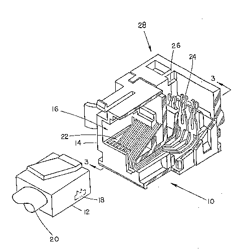
Figure 1 is a pictorial view showing the electrical jack of
the subject invention and an associated plug.
- Figure 2 is a front elevational view of the jack of Figure 1.
~ Figure 3 is a sectional view of the jack of Figure 1 taken
- through Section lines 3-3.
- 20 Figure 4 is a pictorial view of one of the contacts of the
- jack of Figure 1.
Figure 5 is a plan view of the contact of Figure 4 prior to
it being formed into the shape shown in Figure 4.
Figure 6 is a front elevational view of the termination por-
tion of the contact of Figure 4.
Figure 7 shows the contact of Figure 6 with a wire being
stuffed therein.
Figure 8 shows the apparatus of Figure 6 after the wire
stuffing has been completed.
Figure 9 shows a plurality of termination portions of the
contacts received in the housing of the jack shown in Figure 1.
Figure 10 is a sectional view of the contact of Figure 5 tak-
en through Section line 5-5.
Figure 11 shows the apparatus of Figure 10 in contact with a
corresponding plug contact.
- - - - - - - -20633~1
-
Figure 12 is a partial side elevational view of the bearing
portion of the apparatus of Figure 4 in contact with a plug con-
tact wherein the view of Figure 11 has been rotated 90.
, Figure 13 shows the same view as Figure 3 but with a plug
5contact having made contact with the jack spring contact.
DESCRIPTION OF THE PREFERRED EMBODIMENT
Referring now more particularly to Figures 1 through 13,
there is provided electrical connector 10 in the form of an FCC
type jack. An associated FCC plug (not shown~ is ready to be
10mated with the jack 10. Jack 10 includes plastic housing 14 hav-
ing cavity 16 therein for receiving plug 12. The shape of cavity
16 is regulated by the FCC so that standard FCC plugs 12 may be
received therein. Plug 12 includes a plurality of fixed contacts
18 which are terminated to the wires in cable 20. Cable 20 is
15normally connected to a telephone handset or other telecommunica-
tion device.
Jac~ 10 includes a plurality of elongated spring contacts 22.
- In this ~mho~; -nt eight spaced apart spring contacts 22 are uti-
lized.
20As can be seen from Figure 3, there are long spring contacts
24 and short spring contacts 26 so that the contacts may be termi-
- nated to wires in an offset arrangement with alternating long and
short spring contacts.
As can be seen from Figure 4, each spring contact 22 includes
2Sbearing portion 30, an arcuate portion 32, a mid or intermediate
portion 34, a termination portion 36, and an upward bend 38.
Bearing portion 30 includes free end 40. Bearing portion 30 makes
contact with a fixed contact 18 in plug 12. Arcuate portion 32
provides for the primary spring action of contact 22 to impart
30forces at the bearing position 30 when it is deflected. Mid por-
tion 34 is enabled to flex downwardly when bearing portion 30 re-
ceives force from plug 12 thus relieving some of the stress in
arcuate portion 32. Termination portion 36 includes insulation
- displ~c ~nt terminal 40 which receives insulated conductor 28 for
35terminating the insulated conductor 28 to contact 22. Bend
--6--
~_ 2063321
portion 38 is provided in order to elevate the termination portion
36 above the r,: -in~Pr of the contact.
As can be seen from Figure 5, contact 22 is stamped from a
piece of sheet metal and thus is of a thin somewhat flat design.
The arcuate portion 32 is wider than the bearing portion 30 and
the mid portion 34 in order to provide added strength in the
arcuate portion where most of the stresses occur during deflec-
tion. Preferahly the width of the arcuate portion is .024 inches
and the width of the bearing portion 30 and the mid portion 34 are
each .017 inches.
As can be seen from Figures lO and 11, side 42 of bearing
portion 30 which makes contact with plug contact 18 is curved,
thus contact occurs in a very small area 44 thereby resulting in
extremely high pressures where contact is made which tends to cut
through any surface films which are formed on the metal thereby
providing a very good electrical contact.
- . I The free ends 40 of contact 22 are guarded inside of cavity~ 16 by means of comb 46. Comb 46 also prevents a child's fingers
- from being trapped by the ends of the contact.
Housing 14 includes ledge 48 upon which rests the part of
contact 22 near the junction of arcuate portion 32 and mid portion
¦ 34. By providing ledge 48, space 50 is formed by the gap between
the bottom 52 of the jack body and contact holder 54. Space 50
enables the mid portion 34 of contact 22 to flex downwardly, as
shown in Figure 13, when forces are applied on bearing portion 30
caused by the insertion of plug 12 into cavity 16. By permitting
mid portion 34 to deflect downwardly, stresses are relieved on
arcuate portion 32.
A part of mid portion 34 as well as curved portion 38 of con-
tact 22 is held within the connector by support 56. Support 56
includes a plurality of lands 58 which contact the shoulders 60 of
termination portions 36.
As can be seen from Figure 9, wire 28 is stuffed into the in-
sulation displacement contact 40 of termination portion 36 by
3s means of a downwardly pressing stuffer 62 resulting in substantial
downward forces at the termination portion 36 of contact 22.
- - 2063321
Because of the shoulders 60 and the corresponding lands 58, the
downward force is not transmitted to the remainder of the contact
22 which could result in deformation of the remainder of the con-
tact, particularly at the curved portion 38.
Contact 40 may be made of various ~etals including phospho-
rous/bronze alloys and beryllium copper alloys. Beryllium copper
alloys are much more expensive than phosphorous/bronze alloys and
are widely used because of the ability of beryllium copper to re-
turn to its original shape when under large stresses, whereas
phosphorous/bronze is not so forgiving. However, because of the
design features described herein, one is able to utilize the
! cheaper phosphorous/bronze alloys without sacrificing relia~ility.
Thus by widening arcuate portion 32, providing of ledge 48 and the
resulting space 50 in the jack, and providing the contacting
shoulder 60 and land 58 at the termination end of the contact, one
- is able to utilize the cheaper phosphorous/bronze alloys while
! substantially reducing the fear that the contact will be over-; stressed as a result of overdeflection of the arcuate portion 32
or as a result of the high forces applied during the insertion of
wire 28 into insulation displacement contact 40.
Insulation displacement contact portion 40 of the terminatlon
end 36 is designed sc as to enable one to utilize both solid and
stranded wire, thus making the jack much more flexible. The insu-
~ lation displar~nt contact 40 includes wire entry opening 64
formed by jaws 66 and 68. The contact 40 includes slit 70 which
is formed in the contact by shearing rather than the typical
stamping. This shearing of the contact results in a substantial
zero clearance between beams 72 and 74 which provide the forces
for terminating wire 28 to contact 22. Because of the zero clear-
ance as opposed to a gap with a width equal to the metal thickness
which is normally provlded in an insulation displaccment contact,
- a substantially better termination of the wire 28 occurs. Hole 76
is provided to add to the flexibility of the beams 72 and 74, en-
abling the beams to become open as shown in Figure 7 as wire 28 is
forced into termination by stuffer 62 as shown in Figure 9.
2063~21
As can be seen, the contact is resilient enough to flex out-
wardly as wire 28 enters the slit portion 70. However, because of
! the substantial zero clearance even if the individual strands 78
and a stranded wire become perfectly aligned, as shown in Figure
- 5 8, the contact is enabled to fully close onto the individual
strands forming an excellent termination thereof.
From the foregoing description of the preferred embodiment of
this invention,-it is apparent that many modifications may be made
- therein without departing from the true scope of the invention.
- i
-- ! .
... ..
~.. ~ ..... ..