Note: Descriptions are shown in the official language in which they were submitted.
2063504
FOOT PROSTHESIS HAVING AUXILIARY ANKLE CONSTRUCTION
Backqround of the Invention:
This invention relates to foot prostheses in general,
and speclflcally to a prosthetlc foot characterized by a unltary
foot and heel constructlon, and/or an auxlliary ankle
construction whlch permlts the flexlblllty of the prosthesls to
be selectlvely determlned and easily changed. The inventlon also
includes an improved coupllng for attachlng sald foot prosthesls
to an auxiliary pylon tube.
The prior art is replete with various types of
mechanical devices purporting to solve the foot prosthesis
problem. Typical of early devices is U.S. Patent No. 2,075,583
issued June 30, 1937 naming Lange as lnventor, whlch incorporates
a rubber form mounted ln operatlve relationshlp with a rigid
metalllc core. Exemplary of the latest developments ln the fleld
ls U.S. Patent No. 4,645,509 naming Poggl as inventor and issued
February 24, 1987, whlch teaches a prosthetic foot incorporatlng
a monollthlc keel or beam of relatlvely masslve proportions
lntended to react to the load of an amputee's body durlng
walking, running, iumping, and the like and to rel'ease the
resultant stored energy to create foot lift and thrust
complementlng the amputee's natural strlde.
., ~
2063504
- However, each of the prior art devices has significant
deficiencies; specifically, the component parts of the
prosthesis, as in Lange, are too heavy and too rigid or, as in
Poggi, are too masslve and monolithic to respond properly to the
nuances of stress-response gradients characteristic of the human
foot.
One of the primary factors which has inhibited the
creation of a truly successful prosthetic foot has been the
fixation of the prior art with the duplication of the structural
aspects of the skeletal and muscular components of an actual
human foot. In many instances, as exemplified by Poggi '509,
mentioned hereinabove, even the toes of the foot are attempted
to be duplicated by providing simulacra thereof. It is this
fixation upon the mechanical elements of the human foot which has
restricted the art to an attempt to duplicate the human foot
components, a tendency which is particularly exemplified in U.S.
Patent No. 3,335,428 issued August 15, 1967 naming Ga~dos as
inventor.
My U.S. Pat. No. 5,037,444, issued August 6, 1991,
'discloses certain concepts relating to a prosthetic foot
characterized by a forefoot portion and a heel portion which may
be permanently or demountably associated with each other whereby
both the forefoot portion and the heel portion can be readily
exchanged with correspondingly constructed heel and forefoot
portions. This exchangeability permlts size
B
CA 02063~04 1998-03-0~
adjustment or accommodation of different spring rates to suit
the size of foot of the amputee or the stride and weight of
the amputee, yielding an almost infinite range of combinations
of spring rate and size to the amputee, and allowing a natural
stride and resilience of gait which has to been obtainable by
prior art prosthetic devices. The invention of my U.S. Pat.
No. 5,307,444 utilizes a horizontal attachment surface for
attaching the prosthesis to a pylon, however; this horizontal
attachment surface imparts some limitations on size, weight
and performance of the prosthesis, as well as in difficulty
and expense of manufacture, which limitations are not present
in the instant invention.
Summary of the Invention:
In one embodiment my invention provides a foot prothesis
which is characterized by a fore-foot portion and a heel
portion which may be permanently or demo~ntably associated
with each other, with the forefoot portion having an upwardly
extending attachment section providing ease of manufacture and
resistance to rotation, whereby both the forefoot portion and
the heel portion can be readily exchanged with correspondingly
constructed forefoot and heel portions to provide size
adjustment or accommodation of different spring rates to suite
the size of foot of the amputee or the stride and weight of
the amputee, and further adjustments can be made by the use of
an auxiliary ankle spring member. Therefore, an almost
infinite combination of spring rate and size can be provided
CA 02063~04 1998-03-0~
to the amputee, achieving a natural stride and resilience of
gait, which has not been obtainable by prior art prosthetic
devices.
In another embodiment the invention provides a prosthetic
foot of the aforementioned character having an interchangeable
or permanent forefoot portion which has a toe section, an arch
section, a curvilinear ankle section, and an upwardly
extending attachment section, all constructed without the
necessity of tapering of the thickness thereof. Also
incorporated in the aforementioned foot is a heel portion
which has an attachment section secured to the intersection of
the arch and toe sections of the forefoot portion and a heel
section extending beyond the curvilinear ankle and attachment
sections of the forefoot portion. The heel section extends
beyond the curvilinear ankle and attachment sections of the
forefoot portion.
As previously indicated, the forefoot portion can be
provided in different sizes and spring rates, and an auxiliary
ankle member may be utilized, thus permitting the gait,
weight, and activity level of the amputee to be readily
accommodated. Correspondingly, the forefoot portion can
be demountably associated with the heel portion of the foot to
permit different sizes of heel portion having different spring
rates to be mounted in operative relationship with the
forefoot portion.
CA 02063~04 1998-03-0~
In another embodiment the invention provides a prosthetic
foot of the aforementioned character in which both the
forefoot and heel portions of the foot are fabricated, and the
auxiliary ankle may be fabricated, from superimposed laminates
maintained in operative relationship by an encapsulating
polymers, and further in which said toe, arch, ankle and
attachment sections of said forefoot portion, said heel
section of said heel portion, and said auxiliary ankle
attachment are susceptible to bending stress determined by the
number of the laminates and polymers in the respective toe,
arch, ankle and attachment sections of said forefoot portion,
in said heel section of said heel portion, and in said
auxiliary ankle attachment. Thus, the various portions and
sections thereof are encapsulated in a polymer and capable of
spring stress response as ankle loads are imposed thereupon
during the utilization of said foot.
In another embodiment the invention provides a prosthetic
foot of the aforementioned character, having a forefoot
portion which consists of continuous, integrally and
simultaneously formed toe, arch, ankle and attachment
sections, said sections being fabricated as a unitary
structure by polymer impregnation of superimposed reinforcing
laminae maintained in the desired configuration of said
forefoot portion and said toe, arch ankle and attachment
sections being capable of spring stress generated energy
storage whereby the subjection of the toe sections to bending
moments will cause uniform transmission of spring stress
CA 02063~04 1998-03-0~
through said arch section and through said curvilinear ankle
section of said forefoot portion to said attachment section
thereof.
Alternatively, chopped fiber or other suitable
reinforcing material may be utilized instead of or in addition
to the aforementioned laminates.
In another embodiment the invention provides a prosthetic
foot in which the curvilinear ankle section of said forefoot
portion has its upper extremity constituted by said upper
attachment section and its lower extremity extending into and
constituting said arch section, said lower extremity, said
curvilinear ankle section and said upper attachment section
maintaining an approximately uniform thickness transversely of
the longitudinal axis of said sections. Similarly, said heel
portion and its various sections are provided with an
approximately uniform thickness transversely of the
longitudinal axis of said sections.
In another embodiment the invention provides an auxiliary
ankle attachment, which is associated with the ankle section
of said forefoot portion to increase the resistance of said
ankle section to loads imposed upon the toe section of said
forefoot portion. The concept of the auxiliary ankle involves
the provision of ankle members characterized by different
spring rates, which permits the resistance of the ankle
section to deflection to be precisely adjusted to the weight,
CA 02063~04 1998-03-0~
activity level and other characteristics of the individual for
whom said foot is being adjusted.
The polymers utilized to encapsulate the fibrous laminae
are characterized by elastlcity and flexibility so that the
forefoot and heel portions deflect proportionally to the
engagement of said forefoot portion with an adjacent surface,
causing the resultant energy to be stored and subsequently
released when the gait of the amputee incorporating thrust and
lift components results in the utilization of the stored
energy and a consequent reduction of the energy expended by
the amputee. There is a gradual increase in stiffness as the
lever arm of the toe section of the forefoot portion shortens
due to gradual deflection thereof.
In another embodiment my invention provides an improved
coupling mechanism for attaching a prosthetic foot of the
above mentioned character to an auxiliary pylon tube which is
in turn attached to the wearer's leg.
In order to impart a cosmetic aspect to the prosthetic
foot, after proper fitting of the foot to insure that the
forefoot and heel portions and the auxiliary ankle are
properly balanced and of appropriate size, the prosthesis may
be encapsulated in a suitably shaped foot-like shroud to
facilitate the utilization of the prosthetic foot with a
conventional shoe. The enclosure must be sufficiently
flexible so as not to inhibit the free movement and flexure of
CA 02063~04 1998-03-0~
. .
the forefoot and heel portions and the auxiliary ankle of the
prosthetic foot, but, because of the inherently resilient and
stress-absorbing characteristics of said foot, little
dependence is needed upon the ancillary cushioning action of
the enclosure.
In another embodiment my invention provides a prosthetic
foot characterized by extreme light weight, instantaneous
response to imposed loads and correspondingly instantaneous
delivery of stored energy when the gait of the wearer
indicates that such stored energy is to be released.
Moreover, the foot may be readily mounted in operative
relationship with conventional ancillary pylons and couplings,
and can be fine-
15= ~
~=
2063504
~tuned by the blending of the forefoot and heel portions andauxiliary ankle characteristics to achieve the ultimate ln
operatlve response to the needs of the wearer.
Consequently, the wearer of the foot may engage in a
wlde variety of actlvities which were precluded ln the past
because of the structural llmltatlons and correspondlng
performances of prior art prostheses. Running, ~umping and other
activities are sustained by the foot and it amy be utilized ln
the same manner as the normal foot of the wearer.
In accordance with one aspect of the lnvention, there
is provided a foot prosthesis adapted to be demountably secured
to a vertlcally orlented rlgld pylon member for provldlng
kinematlc support to an amputee relative to the ground,
comprlslng:
a forefoot member detachably secured to and extendlng
relatively downward and forward from the rigld pylon member. The
forefoot member is formed of a resillent and flexlble material
and ls adapted to store and release energy by bending ln response
to a downward compressive force exerted by the amputee. The
forefoot member foot comprlses:
a substantlally vertically oriented upper attachment
sectlon adapted to detachably secure sald forefoot member to the
rlgid pylon member;
a relatively stiff ankle section capable of resisting
excessive bendlng of the forefoot member, the ankle section ls
configured to bend in a manner analogous to the manner in which
2063504
~-a normal human foot pivots about a normal ankle ioint;
a relatively compliant toesection extending relatlvely
forward from the ankle section defining a forward lever arm of
said foot prosthesis; and
a heel member detachably secured to and extending
relatively downward and rearward from said forefoot member
defining a rearward lever arm of sald foot prosthesis.
The forefoot member can be readily detached from the
rigid pylon member and is interchangeable with like forefoot
members having different resiliency characteristics such that a
wide range of varying actlvity levels may be sustained ln a
single foot prostheses.
In accordance with another aspect of the present
invention, there is provided a lower limb prosthesis adaptable
to a socket fitted to the stump of a lower-limb amputee for
providing resilient kinematic support to said amputee during
normal walking, running and ~umping activities, comprising:
a substantially rigid tubular pylon member having a
proximal end adapted to engage said socket and a distal end
extending substantially vertically and termlnating at about the
location of said amputee's normal ankle ~oint, said distal end
having front and rear sides; and
a detachable flexible foot prosthesis comprising a
spring-like foot member adapted to be selectively attached to
said distal end of said tubular pylon member according to a
particular desired activity or a particular desired degree of
kinematic resilience, said foot member further comprising:
9a
2063504
_ an upper attachment sectlon havlng a substantlally
vertlcal mountlng surface adapted to closely recelve a
correspondlng substantially vertlcal mountlng surface dlsposed
on said rear side of said distal end of said tubular pylon
member;
an intermediate ankle section formed integrally wlth
and curving substantially continuously downward and forward from
said upper attachment section such that bending stress is
distributed substantially evenly therethroughout;
a toe section having a proximal end and a distal end,
said proxlmal end being formed integrally with said intermediate
ankle section and said distal end extending forwardly to
correspond to the toe of the user, said toe section curving
substantially continuously forward from said proximal end to said
distal end thereof such that bending stress is distributed
substantially evenly therethroughout, said toe section meeting
the ground at a point near said distal end of sald toe section
to define, together with said ankle section, a forward lever arm
for said foot member for returning substantial energy to said
~0 user during toe off; and
a heel member extending substantially contlnuously
rearward and downward from a polnt tangentlal to sald
lntermedlate ankle sectlon such that bendlng stress is
distrlbuted substantlally evenly throughout sald heel member,
sald heel member providing a rearward lever arm for said foot
member;
sald heel member and said toe section providing substantially the
sole support for loads incurred by sald flexlble foot prosthesls
9b
2063504
-durlng heel strike and toe off, respectlvely;
whereby said foot member can be readily detached from
said tubular pylon member and is interchangeable with like feet
members having different resiliency characteristics without
having to change or adiust sald socket or the length of said
tubular pylon member, such that a wide range of varylng actlvlty
levels may be sustained in a slngle prosthetic device.
In accordance with yet a further aspect of the present
invention, there is provlded a lower limb prosthesis adaptable
to a socket fitted to the stump of a lower-limb amputee for
providing reslllent kinematic support to sald amputee durlng
normal walklng, running and ~umping actlvltles, comprlslng:
a substantlally rlgld tubular pylon member having a
proximal end adapted to engage said socket and a dlstal end
extendlng substantially vertically downward and terminatlng at
about the locatlon of sald amputee's normal ankle ~olnt; and
a detachable flexlble foot prosthesls comprlslng a
sprlng-llke foot member adapted to be selectively attached to
sald dlstal end of said tubular pylon member according to a
particular desired activity or a particular desired degree of
kinematic resilience, said foot member further comprising:
an upper attachment section having a substantially
vertically oriented attachment surface adapted to attach sald
~5 foot member to sald tubular pylon member;
an lntermedlate ankle sectlon formed lntegrally wlth
and curvlng substantially continuously downward and forward from
said upper attachment section such that bending stress is
i
,~,
CA 02063~04 1998-03-0~
distributed substantially evenly therethroughout, said
intermediate ankle section providing substantially the sole
support for all vertical, transverse and torsional loads
transmitted through said tubular pylon member to said flexible
foot prothesis;
a resilient toe section formed integrally with said
intermediate ankle section and curving substantially
continuously forward therefrom such that bending stress is
distributed substantially evenly therethroughout, said toe
section defining a forward lever arm for providing
substantially the sole support for all vertical, transverse
and torsional loads transmitted through said flexible foot
prosthesis during toe off; and
~5
a resilient heel member extending substantially
continuously rearwardly from said intermediate ankle section
such that bending stress is distributed substantially evenly
throughout said heel member, said heel member defining a rear
lever arm for providing substantially the sole support for all
vertical, transverse and torsional loads transmitted through
said flexible foot prosthesis during heel strike;
whereby said foot member can be readily detached from
said tubular pylon member and is interchangeable with like
feet members having different resiliency characteristics
without having to change or adjust said socket or the length
of said tubular pylon member, such that a wide range of
9d
CA 02063~04 1998-03-0~
varying activity levels may be sustained in a single
prosthetic device.
Other embodiments and modifications of the invention will
be apparent from the following specification and the
accompanying drawings, which are for the purpose of
illustration only.
Brief Descri~tion of the Drawinqs:
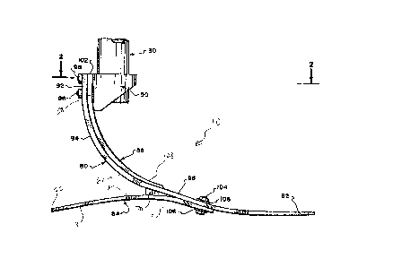
FIG. 1 is a side elevation view of portion of a
prosthesis constructed in accordance with the teachings of the
invention;
FIG. 2 is a partially sectional plan view, taken along
line 2-2 of FIG. 1;
FIG. 3 is a front elevation view, taken along line 3-3 of
FIG. 2; and
qe
2063~04
FIG. 4 i~ a partially sectional side ele~ation
~iew, taken along l~ne 4-4 of ~IG. 2.
Pescri~t;on o~ Pr~ferred F~?di~
Referring to t~e dxawin~c, and particularly to
FI~S. 1 and 2 thereof, ~ ~how a foot prosthe8i~ lO con-
~tructed in accoraance with the toAc~gs of the invention
and including a forefoot portion ~0 an~ a ~eel portion 84
operatively and demountably connectea to each other by bolt
an~ nut combinations 104 associated wit~ load-~ransmitting
metallic plates lO~. If indicated, the forefoot and heel
portions can be permanentl~ Se_~L~ to each other, as by
epoxy adhesive or the like.
The for~oot portion 80 of the pro ~hesis lO in-
clude~ a substanti~l~y rigid upper a~tachment ~ection 92 r a
cur~ilinear a~kle sRction 94, ~n arch ~ection 96 and a toe
section 82. The sections 92, 94, 96 and 82 of the ankle
portion 8~ are preferably formed integrally with one another
and simultaneously by 5he incorporation of a plurality of
laminae embedded ~n a hardened, flexible polymer. Altern~-
tively, chopped fiber or other suitable reinfor~ing materialmay be ~t~l~zed instead of or in addition to the afore~en-
tion~d laminae.
2063504
,.
The attachment ~ection 92 inçoL~o~ates two cen-
trally-lo~ated openings 88, FIG. 4. The attachment se~tion
92 i~ ~ubstantially rigid and capable of sust~ining tor-
sional, imp~ct and other loads i~pressed thereupon by t~e
an~le portion 80 and heel portion 84 of the pro~thesis. In
additio~, the inherent rigidity of the attachment section 92
cause~ t~e e~fecti~e transm~sion of the aforesaid load~ ~m-
posed theLeupG~I to a ~uita~le ancillary prost~etic py~on 30,
by bolt and nut com~inations 98 assembled thr~ugh openings
88 ~o a pylon coupling 9~. A s~rew loo or other suita~le
attachment means Be~ S the anc~l~ary pylon 30 in the cou-
pling 90.
In the partlcular embodiment o~ ~IGS. 1-4, the
auxili~ry ankle 86 is mounted b~tw~en the coupl1ng 90 and
1~ ankle por~ion 80, and ~s ~ec~L~d in operative relat~onship
with the ankle portion ankle se~tion 94 through the use o~
centrally-loçated or6~n7~ in an atta~hment section 1~2 o~
the ankle member 86, wh~ch o~o~;n~c are substantially
aligned with o~in~s 88 of t~e ankle portion attach~ent
section 92. Bo~t ~na nut combinations 98 retain the variou~
com~G,.2nts in the aforecaid operati~e relationship. Al~er-
nati~e ~h~mentS would in~lu~e securing the aux~liary an-
kle 86 to a rearwa~d ~urface o~ the attachment section ~2.
2063504
In the preferred e~bodi~ent, bolt and n~7t combina-
tions 104, in conj~nction with the load-~istributing metal-
1ic plate~ 106, serve to sec~re the heel port~on 84 in oper-
ative re~ationchip with ths forefoot portion 80 of the pros-
t~esis. Thi~ mode o~ affixation facil~tates the assembly ordismounting of ~elected heel portions 84 in operati~e rela-
tionship with selected foxe~oot portions 80, thus per~itting
a wide range of differen~ ~izes and stress load r~on~e
characteristics to be r~lated to each other to accomplish
the optim~m functional co~l~O~,or~nce between the forefoot
and heel portions ~0 a~d 84.
An auxil~ary an~le me~ber 86 can be util;z~d to
decrease ~he flexibility of the ~ore~oot heel porti~n 80.
The ~Y~ ry ankle 86 i~ form~d fro~ fibrous la~inate~ of
the 6ame c~arac~er as the ~arious portionf of ~he pro~the~;is
10. In the prefsrred s~bodimsnt, the auxiliary ankle 86 in-
c~,~oYate~ an atta~hment ~ection 102 which is operat~vely
associated wi~h the couplin~ 90 and the upper attachment
~ection 92 of t~e forefoo~ portion 80, and pre~erably there-
20 beL~raes~. The auxiliary an~le 86 is preferably S~L~ inoperative relatiQ~ r with ~he curvilinear ankle se~tion 94
of forefoot portion 80 through the aforementionQd assembly
of the coupling 90 with the bol~ and nu~ combinations 98.
On its end opposite ~rom the attachment section ~2, ankle
2063504
member 8~ ~as a tapered section 1~8 which provide~ a varying
flexibility along the length of the ankle member 86 and al~o
lessen~ the likelihood that the a~kle member 86 will be un-
desirably ~nagged or restrained in it~ cooperat~e rela-
s tionship with ~orefoot ~oxtion 80 and the cos~etic cover o~
the prosthesi~, ~ore thG~ vuy~ di~cu~e~ beloW. In alter-
native e~bodiments, as will be understood by tho~e skilled
in tne art, ~uch tape~ing is not required i~ order to prac-
~ice the invention, and accor~in~ly, the ankle member 86 can
be provided with a xelat~ely uniform thio~ along the
length thereof.
In the preferred e~odi~ent, the auxiliary ankle
~e~er 86 is se~e~ against the ~elatively internal radius
of the curvilinear an~le section 94, so that t~e anticipated
u~war~ deflection of a toe section ~2 of the for~foot por-
tion 80, as more t~oroughly described be~ow, will ev~ ually
cause de~ormation o~ t~e auxiliary anXle 86 as well as de-
formation of t~e an~le section 94, e~fectively combining the
deformation resistance and el,~.yy s~orage ch~racteri~tics of
the auxiliary an~le ~em~er 86 with tho~e of the ankle sec-
tion 94. Alte~native em~od~ment~ would includQ securing the
auxi~iary ankle 86 ~o the rearward surface of the attachment
~ection 92 and further securing the auxiliary ankle apered
section 108 to an under 6urfac~ 62 of the anXle ~ection 9~
206~04
in order to achieve the aforedescribed desirsd com~ination
of the deformation resistance and energy ~torage character-
istics of the auxil~ary ankle me~ber 86 with tho~e of the
ankle section 94.
The auxilia~y ankle ~ember 86 can be pro~ide~ wit~
different number6 of laminates to ma~e it ~ore or les~ co~-
pliant to loads ~ransmitted throug~ the ankle ~ec~ion ~4.
Con~equently, w~en con~ronted with various anomalies in an
amputee, such as over~eight or exc~ss ac~ivity levels, the
ba~ic structure of tne forefoot portion 80, and mo~e partic-
ular~y the ankle section 94, can be materiall~ modi~ ed to
proYide ankle portion action wh~c~ is precisely ad~u~ted to
the needs of the amputee. Moreover, a variety of auxiliary
an~le membexs B6 can be mad~ ~ailable to an ampuSee, allow-
ing the flexibility of the prosthesi~ to be ~djusted on the
~asi~ of the particular activity which the ~mput~e i6 under-
taking~
As previou~ly ment~oned, a cosmetic cover, not
shown, can be pro~ided to ~hroud the prosthe~i~ 10 a~ter t~e
optimum assemblage of the forefoo~ and heel portions 80 and
84 and any ~xiliary ankle member 86 has ~een acco~pli~ed.
Unlike prior art construction~, hc~ , the cosmetic cover,
which may be formed of low-density formed polymer, i5 not
regu~red to ser~e any anc~llary shoc~-absorbing or other
14
2063504
stre~s-isolating f~nction since all of ~he loads im~G~6A
upon the prosthesi~ ~an be a~sorbed, transmitted and re-
as~erted in a manner to be descri~ed in grQater detail be-
low.
The bolt and nut combination~ 104, in conjunction
with ~he load-di~ri~uting metallic p~ate~ ~06, ser~e to se-
cure the heel portion 84 in operat~ve relation~p with the
forefoot portion 80 of the prosthesis.10, a~ b~st shown in
FIGS. 1-2 of t~e drawings. The aforesaid mode of affixation
facilitate~ the ~ssembly or dismounting of ~elected heel
portions 84 in operativ~ ~elationship with selected forefoot
portion~ 80 of t~e pros~hesis 10, thu~ permitting a wide
range of di~ferent eizes and stre~s load response char-
acteristics to ~e ~elated to each otber t~ accompl~sh the
optimu~ functional cG L~on~le~ce ~etween the forefoot a~d
heel p~rtions 80 ana 84 to ac~ommodate to the m~ximum extent
the needs of ~he wearer of the prosthesis, and, al~o, to
pro~ide for a proper mating of the prosth~sis 10 with 8 ~e-
lected, ancillary py~on 3~ or the like.
The ~orefoot portion 80, as ~est ~own in ~IG. 1
of t~e drawings, includes a toe Qection 82, an arch sectioh
g6, a curvilinear ankle section 94, and an a~tac~ment sec-
tion 9~. T~e heel portion 84 in~lude~ an attachment se~tion
22 and a heel sec~on 28 which preferably has its rearwaxd
206350~
extre~i~y 56 ext~n~ing beyond an ~xtreme rQarward ~urf~ce 58
of ~e forefoot portion attachmen~ section 92 of the pros-
thecis 10. Mating ~ores, not shown, in the arch section 96
of ~e forefoot por~ion 80 and the heel portion 84 ~eceive
the re~pective bolt and nut combinations 104 to pro~i~e ~or
t~e aforesaid facility in a~embling and ~ rcmbling of
the forefoot and heel portions 80 and 84. In the p~efe~red
emb~diment, the various ~ection~ of the forefoot port~on 80
are all constructed withou~ the necessity of tapering ~f the
thickne~s thereof, alt~ough tho8e skill~d in the art will
understand th~t the invention ~ not limited to such non-ta-
pering ~n~uction.
Interpo~ed between ~he under surfa~ 62 of the an-
~le sec~ion 94 of the heel por~on 8~ and an upper sur~ace
64 of the heel section 28 is a resilient, spring action
function ~lock 70 of wed~ ape~ configuration to ~etermine
the le~er arm of t~e heel ~ection 28 and ~olate the under
surface 62 of t~e anXle section 94 and ~he U~L surface 64
of the heel section 28 fro~ each other. T~e fun~tion block
70 may ~e fabricated fro~ a wide ~a~iety of r~silien~ mate-
rials, including natural and synthetic ~bbers or ~e like.
The materi~ls ~rom wh~ch the ~orefoot portion 80
~nd heel portion 84 and the auxiliary anXle 86 are fabri-
ca~ed ~us~ ~e such ~s to pro~ide an energy-storing, re-
206350~
silient, spring-lik~ effect. ~hi# ic nece~sary because each
engagement of the prosthecis 10 with an adjacent ~urface im-
precse~ compression, torsional and ot~er loads upon the
pro~thesis 10 which m~st be stored within ~e prosthe~is and
then, dependent upon ~he stride o~ the ~earer, ~e reim-
pressed upon said surface to achie~e a natural stride con-
foxming, ideally, în all re~ s to t~e stride of the unim-
paired l~mb o~ ~he w~arer of the ~rost~e~is 10.
~e forefoot and hee~ portions 80 and 84 and the
a~xiliary ankle 86 of ~he prosthesis are pre$erab1y molded
~-~ unitary co~ponents and are carefully formed to prov~de
for uniform absorption of stress imposed the~u~ . m e
configuxat~on of both portlons 80 and 84 i~ o~ utmost impor-
tance and the ~l.o~d f~ers, laminates, or other reinforc-
lS ing material~, and the poly~er or polymer~ from whi~h theport~ons 80 and 84 are fabricated ~u~t be resil~ent and ca-
pa~le of absorbing the compre~sive, torsional and other
etre~ses referred to herei~hove and of rest~ring the stored
energy created by such s~e~es, in a na~ral ~anner, to the
impacted surface w~ic~ orlginally imro~e~ ~u~h ~tres~es upon
the pros~hesis 10.
It has been found that there ~ a lim~ted number
of polymers capabl~ of s~st~ini~ the significan~ stresses
and repetitive loads impose~ upon the prosthes~s 10, partic-
17
'~ 206350a~
ularly in the l~ght of the countless number~ of ~y~les to
which the pro~thesi~ 10 is subjected ~uring normal, everyday
use .
At present, the best materials for the pro~thesi~
are a composite o~ high-~trength graphite fiber in a hig~-
toll7h~C epoxy ther~o6ettin~ resin system. ~here are sev-
eral reasons for this: t~ high str~ngth; t2~ gtiffness to
weight rat~o o~ graphite as compared to oth~r ~at~rial~; t3)
the almost comple~e return of input or stored energy: (4)
ligh~ weight; ~5) high fatigue s~rength; and ~) minimal
creep. As an alternative material, fiberglassfepoxy is a
fair choice, but it is not ~s good as graphite because of
lower fatigue st~ength and highe~ den~ity. ~evlar i~ e~en
le~s acceptable due to poor compression and shear strength,
althou~h it is the lowe~t density of those mentioned~
An i~portant ~spect of t~e polymers and chopped
fibers or lami~ates referred to ~ereinabov~ i~ tha~ they are
characterized by n~e~o~, but not eY~-r_ci~e, flexural deflec-
tion under lo~d, which'characteri~tic permits the ~hoc~-ab-
sorption stress lo~ng o~ the pros~he~is 10 while ~R~ntain-
ing sufficien~ sta~ility to ~vcn~ the collap~e o~ the
forefoot ana heel portions 80 and 84 and She ankle member 8
of the prosthesis 10 while loads are imposed t~ere~.,.
2063504
To achie~e the relatively thin ~o~ ruction of the
foot and ankle portions 80 and ~4 and the auxiliary ankle
me~er 86 of the pro~;thesi~ 10, the afore~aid polymers are
utilized in c~njunction with va~ous reinforclng or laminat-
ing materialc. Variou~ types o~ fibrous laminae can be uti-
lized to achieve the contin~um requ~red by the design of the
foot and ankle portions 80 and 84 and the ankle member 86 to
~omplement the stress-ab~or~ing and storing c~aracteri~tics
~f the polymers in which said fibrous lam~nae are em~ A~.
0~ course, t~ere ~s a wide ~ariety of f~brous re-
infor~ements in the form of laminae available at the ~l~_cnt
~ime, including such inorganic ~ibers a~ gla~s or carbon
fiber~. ~hese inorganic fib~rs are cus~omar~ly pro~ided in
tape or s~eet form and can be readily ~uperi~posed in the
mold to penmi~ the~ ~o be encapsulated in the selected poly-
mer~ As set forth above, the fibers may ~lso be chopped or
in ot~er form.
O~iously, the number of superlmposed laminae or
other reinforcing laminae ~nd ~hQ lengths thereof, togeeher
with the thickness of the en~psulating polymer, deter~ine
the stress characteristics of the resultant foot and ankle
portions 80 and 84 and the an~le member 86 and, co~Le~ d-
ingly, determine the total weig~t o~ She prosthes~s 10. As
w~ e apparent ~rom the di~c~lr~ion hereinbeloW, the indi-
20635Q~
vidual foot and anXle portions 80 and 84 and an~le member g~
are de~igned to specifically aCCOmmodate individuals having
different foot cizes, different weights and different
strides and the indi~id~al design of the f~ot and an~le por-
tions 80 and 84 and the ankle member 86 pro~ides for matc~-
ing, to an extent previou~ly unknown in the art, the natural
chara~teri~tics of t~e ~earer'~ uninjured limb.
~urthermore, the function block 70 can be provided
in different sizes and in material~ having different ccm-
pre~sion character~gtics ~o tha~ the lever ar~ and the cor-
r~ ndi~ deflection~ of the heel section 2~ may ~e in-
cre~s*d or decrea6ed.
As previously mentioned, the ankls ~ection 94 is
formed integrally with the ~pper ~ttachment ~ection 18 and
said attachmen~ ~ection constitutes the upper ex~remity of
the ankle ~ection ~4, while the ~ nitiat~on of the arch sec-
tion 96 of the forefoot portion 80 oonstitutes the lower ex-
trem~t~ of the an~le 6ection 94. The configuration of the
ankle ~ection 94, in con3unction ~ith the auxiliary ankle
~o member 86, i~ the means whereLy comprQssive lo~ds im~
during impinge~ent of the foot and ankle por~ions 80 and 84
~pon an adjacent surfaoe are a~~G~L~d and subsequently reim-
po~ed upon said ~urface. The an~le portion 94 and the aux-
ilia~y ankle member 86 are ~o designed that they Punction,
206350~
s~bstantially, as an an~le joint to permit pi~oting of the
forefoot portion 80 thereabout in a manner analogous to the
manner in ~hich ~he normal foot pi~o~s about the normal an-
~le joint about an axi~ transversely of sAid ankle jotnt.
The radii of curvature of the ankle section 94 and
any auxiliary ankle member 86 correspon~ to provide ~or ~he
inherent re~liance and deflection of the ~orefoot portion
80 while inhib~ting un~e~ired, excessi~e collap~e of the ~n-
kle section 94.
It will ke noted that the attachment ~ection 22 of
~he heel portion 84 i~ substantia~ly rigid and that the ini-
t~a~ de~lection of the heel gection 28 v~ c i~mediately
adjacen~ t~e rearward extrem~ty 56 of ~aid h~el ~ection,
terminating immeaiately adjacent the ~unction block 70. Ob-
~iously, a greater length or le~ resilient function block
70 reduces the lever ar~ of the heel seo~ion 28 of the hPel
porti~n 84 and co~e~ y re~uces the ~odulu~ of de-
fl~ction of caid ankle section, while a smaller l~ngth or
more re~ilient function bloc~ 70 incr~ases the lever arm and
correspond~ngly inrreases the de~lection of ~e ~eel sectio~
28 under load.
The toe section 82 and heel ~ection ~8 can be pro-
~ided In different leng~hs to corr~o,.~ to the size of the
foot of the wearer of the prosthesi-~ 10. When ~uch differ-
20635~4
ent lengths are pro~ided, corre~.r~dj ng reduction or ~n-
crease in the number of la~inae and thic~-eFc of taper o~
the resp2ctive toe section 82 and heel section 28 can be
made to provide for t~e proper flexure of said toe and heel
section~. It should also ke noted that, e~en with th~
shortest heel section 28, the re~rward ~x~mity 56 thereof
preferably projects ~_y~l~ the rearward 6urface 58 of the
~refoo~ portion 80. Co~,~eyu~ ly, ~he stabllizing and
~ ab80rption chara~terist~c~ of the heel section 28 of
the prosthe~is lo are always mainta~ned.
Those skilled in the ar~ will understand that many
alternative embodiments of the coupling 90 can be con-
s~ructed and practiced ~nterc~angeably in oPnnQct~on ~ith
the many alte~nati~e embodiment~ of the rest o~ the inven-
1~ t~on.
It will, of course, be o~ious to those skilled i~~Ae art that, with re~p~ct ~o any smbodim~nt of th~ ~nven-
tion, the ~ibrous reinforcements in ~he form of laminae
plies e~ sul~ted ~n the prosthesis may be fayed-o~ tapere~
to acco~plis~ a gra~u~l tran~i~i~n as the number o~ p3ie8 ~S
~e~ in any ~rea o~ the fore~o4~ or heel port~on~
210~e6~eL, if a relati~ely lightweigh~ indi~idual
partakes in sports o~ other ac~ ies which ~ub~oc~ the
prosthesis 10 to grea~e~ loads, a ~eel or for~foot poxtion
. .
22
., .; .
~
2063501
84 or 80 will be ~it~ed which will accommodate for tho3e
greater loads.
The an~le ~ection g4 o~ the forefoot portion 80
deflects under load and the auxiliary ankle member 86 si~i-
S larly deflect~. Additionally, the toe and arc~ ~ections 82
and 96 of the forefoo~ portion 80, and the heel section 28
of the heel portion 84, de~1ect under ~uch loa~. Therefore,
when ~ubjected to vertical compression lo~ds, the ankle sec-
tion 94, the auxiliary an~le membex 86, the arc~ sec~ion 96,
and the toe and heel sections 82 and 28 absorb such load~.
Consequently, there is no ~tress concentration,
e~ther ~n ~he impa~t pha~e when the adj~en~ ~urface is ini-
tiall~ contacte~ ~y the wearer of the prosthesis ~0, or when
return o~ the a~cumula~ed forces ~tored in the prosthesis 10
is acco~plished.
~he cur~ature of the toe section 82 provide~ fo~
maximum accommodation of said sectio~ during ~ur~ace contact
in both the impac~ and del~very ph~se5 of the prosthesi~ 10.
Similar con~iderations apply ~o the curvature o~ th~ heel
~ection 28 of the heel portion 84 of the prosthesis 10. It
will be noted tha~ the curva~ures of the toe and heel sec-
tionc 82 and 28 pro~ide for rela~vely extended levRr arm~
Which achie~e stability and, a}~o, stres~ ~torage and stres~
reaction.
206350~
The prefer~ed ~ethod of ~anu~acturing t~e ~orefoot
and ~eel portions 80 ana 84 a~d the auxiliary ankle member
86 of t~e prosthesi~ 10 is by a thermo~etting ~olding pro-
cess including the utilization of molds having properly
~peA an~ sized ca~it~e~. m e ca~ities are designed to re-
ceive the requi~ite num~er of laminates and the ~e~ ~ol-
ume of polymer.
Unlike priox art unitary de~ice~, the f itting o~
the prosthe~is 10 in~olves the judic~ous aaiustment of the
pxo~thesis by the prop~r combinat~on of for~foot and heel
portions 80 and 84 and auxiliary anXle member 86, ~
tively. It al~o ~nvolve~ the selection of the properly de-
signed ancil~ary pylon 30 which can be s~ e-1 by mean~ o~
the coupling gO to the a~tachment ~;ection g2 of the forefoot
portion 80. only when the proper correl~t~on beL~en ~he
forefoot portion 80, ~eel portion 84, auxiliary anXle member
8fi, and ancillary pylon 30 has been accomplished, can ~he
¢osmetic sh~oud, not shown, ~e instailed upon the assembled,
Le~e~ e porti~ns of'the pr~sthe~is lo.
By the pro~thesis of ~y inven~io~ I provide a foot
which can be carefully matched to the weight, ~tride and
physical characteri~tics of the wearer. Thi~ is accom-
plished by carefully bal~nci n~ the L~e -~ive physical char-
~cteristics of the ~orefoo~ poxtion 80, the heel portion 84,
24
'~ 2063504
the auxiliary ankle memker 86, an~ t~e various ~ections
~hereof.
Moreover, the a~embled prosthesis i8 ~ar lightex
in weight than prior art pros~b~-e~ ~nce the inherent de-
S ~ign and structure of the pros~h~ , the material~ u~ed andthe careful calculation of -~res~ factors o~ the ~om~vn~L~
of t~e pro~thesis permit fin~ L~ in7 of the prosthesis to
the needs of the wearer t~e~eof.
The pros~he~is of my invention has been ~e~cribed
with some particularity ~ut the specific design~ and con-
struction~ disclo~ed are not to ~e ta~en as ~elimiting of
t~e inven~ion in that ~ariou~ mo~ification~ w~ll at once
ma~e themselves apparent to those of ordinary ~kill in the
art, all of which will not depar~ fro~ ~he e~sence o~ the
lS in~ention and all such chA~eo and modi~ications are in-
tended to be encompA~s~A within the ~ o~R~ claims.
2$