Note: Descriptions are shown in the official language in which they were submitted.
2063562
The invention relates to a smelting plant and a
method of operating such a smelting plant.
A smelting plant of that kind is known. It includes
two melting furnaces which are disposed in juxtaposed
relationship and to which melting energy is supplied
alternately by means of a heating arrangement in the form of
arc electrodes. While the melting operation takes place in
one melting furnace, the other furnace i6 tapped and re-
charged and the waste gases from the furnace which is involved
in the melting operation are passed through the other furnace,
for preheating the fresh charge. That provides for more
uniform utilisation of the power supply and an increased level
of productivity. In addition the heat content of the furnace
waste gases which are produced in the melting and refining
procedure is utilised for preheating the charge material of
the respective other melting furnace and the fact that the
waste gases are passed through the charge material means that
the amount of dust produced and thus the loading applied to
the dust removal arrangement which is at a downstream location
are also reduced.
In order to provide that the gases flow with the
maximum degree of uniformity through the material to be
preheated and in order at the same time to prevent the gas
conduit from becoming obstructed by charge material particles
or spattered or splashed molten material, the furnace gases
are taken off through the cover and introduced into the
adjacent furnace vessel in the lower region of the casing
thereof.
In the known smelting plant, the furnace waste gases
cannot be used for preheating charge material in the initial
phase of the melting procedure as in that phase the other
melting furnace is being tapped, maintained and re-charged.
In addition the step of introducing the gases in the
lower region of the wall of the vessel gives rise to problems
because the opening which is required for that purpose is
exposed to the effect of spattered or splashed molten
'~ $ -- '
,~, ~
2 20635
material.
It is also known a smelting plant with an arc
furnace which includes a furnace vessel having a shaft-like
charging material preheater which is arranged laterally on the
furnace vessel and the interior of which, in a region
adjoining its bottom, is communicated with the interior of the
arc furnace through a connecting zone. In its upper region
the charging material preheater has a closable charging
arrangement for charging material and a gas outlet. A
lo smelting plant of that kind permits the thermal energy of the
furnace waste gases to be put to good use as long as the
shaft-like charging material preheater is at least still
partially filled. That advantage is lost at the end of the
smelting phase and during the refining phase when the shaft-
like charging material preheater is emptied, unless special
steps are taken to ensure that charging material is also
retained in the shaft-like charging material preheater, in
that operating condition.
The object of the invention is to permit preheating
of metal charging material with the furnace gases of the
furnace which is operating in the melting mode, and the coarse
removal of dust from said furnace gases by charging material
even during the initial phase of the melting procedure, in
order to make better use of the heat content of the furnace
waste gases and to reduce the total amount of dust involved.
The invention seeks to make that possible without the opening
for introducing the furnace gases of the other melting furnace
having to be exposed to the effect of spattered or splashed
molten material. The invention also aims to provide a method
of operating such a smelting plant.
According to the present invention, there is
provided a smelting plant, comprising:
- a heating apparatus for the supply of melting
energy and two melting furnaces arranged in juxtaposed
relationship and each comprising a furnace vessel including
a vessel cover for closing the vessel, each vessel having a
t .~
2063562
inlet, a gas outlet, gas conduits which are adapted to be shut
off and which respectively communicate the gas inlet of the
one melting~furnace with the gas outlet of the other melting
furnace, respectively, so that, for the purposes of preheating
metallic charging material, the furnace gases produced in the
melting process in the one melting furnace are passed into the
respective other melting furnace, wherein in each melting
furnace, a shaft is provided which is fixed in a holding
structure and which in an upper region thereof has a closable
loading opening for the charging material and the gas outlet
of the respective melting furnace.
According to the present invention there is also
provided a method of preheating and smelting metallic charge
material by means of a heating apparatus in a smelting plant
which comprises:
a) charging a charging material into a first
vessel and a first shaft associated with said vessel, until
said first shaft is at least partially filled,
b) heating the charging material in the first
vessel by the heating apparatus and carrying furnace gases out
of the first shaft into a waste gas chimney;
c) repeating step a) in a second melting furnace;
d) diverting the furnace gases from the first
vessel, which are removed from the first shaft, into a second
vessel and through a second shaft to a waste gas chimney;
e) smelting of the charging material and
metallurgical treating of the molten material in the first
vessel, and subsequently heating the charging material in the
second vessel by the heating apparatus and tapping and
performing maintenance of the first vessel; and
f) repeating steps a) to e).
In the smelting plant according to the invention,
the provision of a shaft which at one side replaces an outer
segment of the furnace cover ensures, throughout the entire
period of time that the heating device is switched on, that
charging material is preheated with the hot furnace gases
.
~.'
-- 2063562
3a
which are produced in the smelting and refining procedure, and
the gases in that situation are filtered, either by the
charging ma`terial in the shaft of the furnace in which the
smelting operation is initiated, or by the charge material in
the shaft of the other furnace when the column of charge
material in the shaft in the first furnace has moved
downwardly to such an extent that it can no longer perform
that function. In that arrangement, the way in which the gas
is passed can be suitably controlled by gas conduits which are
adapted to be closed off.
Preferably the gas inlet is arranged in the upper
peripheral region of the vessel, in the vessel cover or in the
lower region of the wall of the shaft of the melting furnace.
As a result the gas is supplied at a location which is not
exposed to the area of action of spattered or splashed molten
metal or slag.
Preferred embodiments of the invention are described
hereinafter in greater detail with reference to three
diagrammatic Figures of drawings in which:
Figure 1 is a plan view of a smelting plant
according to this invention, with the furnace cover removed
from the left-hand furnace vessel,
Figure 2 is a side view of the Figure 1 smelting
plant, and
Figure 3 shows a view in section taken along line
III-III in Figure 1 of part of the plant shown therein, with
the vessel cover of the left-hand furnace vessel retracted
into the closure position.
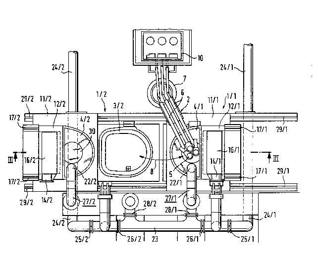
The smelting plant shown in the drawings includes
two melting furnaces 1/1 and 1/2 which are arranged in
juxtaposed relationship,
*~
2063562
and a heating device 2 by means of which heating energy can be
selectively supplied to one of the furnaces 1/1 and 1/2 for heating
the charging material such as steel scrap of the melting furnace in
question, in order to melt it and raise it to a tapping temperature.
Each melting furnace includes a furnace vessel 3/1 and 3/2
respectively, which can be closed by a vessel cover 4/1 and 4/2
respectively.
The heating device 2 is in the form of an electric arc device and
includes three arc electrodes 5 which are each carried by a support
anm 6. The support arms can be raised and lowered and, as shown in
Figure 1 by a double-headed arrow 8, pivoted laterally, by means of an
electrode lifting and pivoting apparatus 7. They may be ved
selectively into the first furnace vessel 3/1 or the second furnace
vessel 3/2 through electrode passage openings 9/1 and 9/2 respectively
provided in the respective vessel covers 4/1, 4/2. In plan view, the
position of the electrode lifting and pivoting apparatus 7 is
determined by the apex of an isosceles triangle, the base of which
connects the centres between the respective three electrode passage
openings 9/1 and 9/2 respectively. The electrodes are connected in the
usual manner to the three phases of a transformer 10 which with the
electrodes permits arc operation for introducing the heat required for
the melting process. In each melting furnace 1/1 and 1/2, at one side
and more particularly in the present case at the side remote from the
adjacent furnace vessel, an outer segment of the vessel cover is
replaced by a shaft 12/1 and 12/2 which is fixed in a holding
structure 11/1 and 11/2 respectively. Each shaft is provided in its
upper region with a closable opening 13/1, 13/2 for the charging
material, and a gas outlet 14/1, 14/2. In plan view each of the shafts
12/1 and 12/2 is of an almost rectangular configuration, with a
dcwnwardly enlarging internal space 15/1 and 15/2. It can be closed by
means of a shaft cover 16/1 and 16/2 which is of the cross-section
20635~2
illustrated in Figure 3, in the form of an inverted U-shape, and it is
horizontally displaceable on rails 17/1 and 17/2. Figure 3 shows the
shaft 12/1 in the closed condition and the shaft 12/2 in the opened
condition in which charging material can be introduced into the shaft
by means of a charging material container 18.
In plan view, the furnace vessels 3/1 and 3/2 are each in the form
of an oval which is delineated by a straight line on one side (see the
left-hand furnace vessel in Figure 1), wherein the lower opening of
the shaft opens into the region of the vessel which is defined by the
straight wall portion and the adjacent portions of the oval. In
addition, in the illustrated embodiment, the vessel cover 4/1, 4/2
is releasably secured to the holding structure 11/1 and 11/2 of the
associated shaft 12/1 and 12/2 respectively.
The furnace vessels are secured in frames 18/1 and 18/2
respectively which in turn are unted on lifting apparatuses 19/1 and
19/2 respectively. Each of the apparatuses 19/1, 19/2 includes four
lifting or stroke-producing cylinders which engage the corners of the
frame which is rectangular in plan view; the lifting cylinders are
rotatably connected on one side to the framesl8/1, 18/2 by way of
hinge connections 20/1 and 20/2 respectively. That design
configuration permits both a lowering vement of the furnace vessels
3/1 and 3/2, and also a tilting vement for tapping the vessels
through a tapping hole (not shown) in the bottom of the respective
vessel. In the view shown in Figures 2 and 3, the tilting movement
takes place perpendicularly to the plane of the paper. Shown beneath
the furnace vessels in Figure 2 are ladles 21/1 and 21/2, for
receiving the liquid metal from the furnace vessels. The electrode
passage openings in the melting furnaces can be closed by a cover
plate 30 when the electrodes are removed (see Figure 3).
In order to be able to utilise the hot furnace gases which are
produced in the melting process and when the molten metal is
206~562
-
superheated to the tapping temperature, for the purposes of preheating
charging material, and at the same time to reduce the loading on the
dust removal arrangement, the plant includes a gas conduit system
which is described hereinafter.
Each of the gas outlets 14/1 and 14/2 respectively can be
selectively communicated by gas conduits which can be closed off,
either to a waste gas chimney by way of a filter device or to a gas
inlet 22/2, 22/1 in the cover 4/2 or 4/1 of the adjacent melting
furnace 1/2 and 1/1 respectively. The gas conduit system of the
illustrated embcdiment will now be described in greater detail with
reference to Figures 1 and 2.
A gas conduit 23, the ends of which are connected to cnm~ln;c~ting
conduits 24/1 and 24/2 going to the dust removal arrangement, is
divided by shut-off members 25/1, 26/1, 26/2 and 25/2 into two outer
gas conduit portions and a central gas conduit portion. The shut-off
members may be for example in the form of sliders or pivoting flaps
which can be actuated by control members. The two outer gas conduit
portions are connected by way of branch conduits to the gas outlets
14/1 and 14/2 of the shafts 12/1 and 12/2, while the central portion
is connected by way of branch conduits and bends 27/1 and 27/2 to the
gas inlet 22/1, 22/2 in the vessel cover of the first and second
melting furnaces respectively. The last-mentioned branch conduit
portions include further shut-off members 28/1 and 28/2.
In the illustrated embodiment the holding structure 11/1, 11/2 of
each shaft, including the cover carried thereby, is displaceable
parallel to the connecting line extending between the centre lines of
the shafts, on rails 29/1 and 29/2. Figure 1 shows the vessel cover
4/2 in the position in which it is moved to the side and in which the
furnace vessel is opened for charging of the content of a charging
material container directly into the furnace vessel. Before the cover
with the holding structure is moved, the respective furnace vessel
- 2063Sfi2
must be lowered slightly by means of the lifting apparatuses 19/1 and
l9t2 .
As can be seen from Figures 1 and 2, the bend 27/2 is fixedly
connected to the gas inlet 22/2 and is moved together with the holding
structure 11/2. The same applies in regard to the bend 27/1 of the
other vessel. The bends must therefore be r~le~hly connected to the
associated branch portions of the gas conduit 23. The same ~pl;~ to
the branch portions of the outer sections of the gas conduit 23, in
relation to the gas outlet openings 14/1 and 14/2 of the shafts 12/1
and 12/2.
Accessibility to the upper opening of the furnace vessel for
directly charging charging material into that vessel could also be
ensured, if the covers are stationary, if the furnace vessels are
movable perpendicularly to the connecting line joining the centre
lines of the shafts. That modification is not shown.
A preferred method using the above-described smelting plant will
now be described.
For the purposes of charging the melting furnace 1/1, the
electrodes 5 are raised and pivoted laterally away. At the same time
the furnace vessel is lowered somewhat by means of the lifting
apparatus 19/1. Thereupon, the holding structure 11/1 is moved on the
rails 29/1 towards the side, that is to say it is moved towards the
right from the position shown in Figures 1 and 2 so that the opening
of the vessel 3/1 is open for the charging operation. After the
content of a first basket has been loaded directly into the vessel,
the cover with the shaft is moved by means of the holding apparatus
thereof into the operative position again and the furnace vessel is
raised by means of the lifting apparatus 19/1 until the edge of the
vessel is tightly sealed to the cover.
Now, with the shaft cover 16/1 in a position in which it is moved
to the side, two or three further baskets are loaded by way of the
shaft 12/1 until the shaft is filled. The volume of the charging
- 2063362
material coLl~onds to that of an entire molten bath. The shut-off
members in the gas conduit 23 are actuated in such a way that the gas
outlet 14/1 of the shaft 12/1 is connected to the connecting conduit
24/1, that is to say the shut-off members 26/1 and 28/1 must be closed
and the shut-off member 25/1 must be opened. After the electrodes 5
have been moved into the operative position for the melting furnace
1/1 by the electrode lifting and pivoting apparatus 7 and the arcs
have been fired, the smelting process in that furnace is initiated.
Instead of or in addition to the arc electrodes, burners may also be
provided as the heating apparatus (not shown).
While the first phase of the smelting procedure is taking place in
the melting furnace 1/1 and the furnace gases which are produced in
that phase are being passed through the shaft 12/1 of that melting
furnace and then to the dust removal apparatus, the second furnace
vessel 3/2 can be charged in the same manner as the first furnace
vessel was charged previously. After the operation of charging that
vessel, when there is a second heating apparatus, for example burners,
and with the shut-off members 28/2 and 26/2 in the closed position and
the shut-off member 25/2 in the open position, it is already possible
to begin the operation of heating that char~e.
As long as the waste gases in the first melting furnace 1/1 are
sufficiently cooled down by the charging material in the shaft 12/1,
those waste gases are passed by way of a fan directly to the filter
installation, that is to say the dust removal apparatus. When the
rising L~"~el~L~res of the waste gases from the shaft have reached a
sufficiently high value and the other melting furnace is charged and
the charge thereof is possibly preheated by the second heating
apparatus, the waste gas is then circulated into the vessel of the
second melting furnace 1/2 and passed through the shaft 12/2 of that
melting furnace. For that purpose the shut-off members 25/1, 28/2 and
26/2 must be closed and the shut-off members 26/1, 28/2 and 25/2 must
be opened. That provides that the gas is passed from the upper end of
2063562
the shaft of the first melting fu m ace 1/1 into the second adjacent
melting fu m ace 1/2 through the cover thereof, and is passed from
there through the shaft 12/2 of that melting fu m ace and is drawn off,
from the upper gas outlet 14/2, into the filter installation. That
provides that the energy of the waste gas is put to very good use,
throughout the entire melting and refining process in the first
melting fu m ace 1/1. At the same time the particles of dust which are
contained in the gas are deposited in the charging material in the
shaft 12/2 of the second melting fu m ace.
When the molten material in the first melting fu m ace 1/1 is ready
to be tapped and the ~L~Liate carbon has been adjusted, the
electrodes 5 are raised and immediately pivot to the second melting
fu mace 1/2 so that there they can immediately begin the melting
procedure after the shut-off members have been changed over, in a
~imil~r manner to the procedure described above in relation to the
melting fu m ace 1/2. At the beginning of the melting procedure in the
second melting fu m ace 1/2, the shut-off members 26/2 and 28/2 must be
closed and the shut-off member 25/2 must be opened. The first melting
fum ace 1/1 can now be tapped by actuating the lifting apparatus 19/1
at one side. The tapping hole is then checked and filled and
immediately thereafter the ~h~le of the charging material for the next
molten bath is introduced into the furnace vessel or into the shaft.
Here too, when the installation has a second heating apparatus, it is
possible to begin the operation of preheating that charge, with the
shut-off members 28/1 and 26/1 in the closed condition and the shut-
off member 25/1 in the open condition. In the second phase of the
melting procedure in the shaft fu m ace 1/2 the shut-off members 25/2,
28/2, and 26/1 must be closed and the shut-off members 26/2, 28/1 and
25/1 must be opened.
Very good utilisation of the waste gases and filtration of the
waste gases is achieved by virtue of the fact that the fu m ace gases
are firstly passed through the shaft of their own melting fu m ace
20S3562
while the other melting furnace is being tapped and charged, and, when
the temperature of the waste gas of the first shaft has risen
sufficiently or the column of scrap has moved downwardly almost as far
as the level of the vessel cover, as a result of the smelting
procedure, the furnace gases are passed into the other vessel and
there through the filled scrap shaft. The flow of gases can be
diverted in a simple fashion by virtue of control of the shut-off
members.
As, immediately after the charging material has been melted in
the one melting furnace and raised to its tapping temperature, the
electrodes are pivoted to the other melting furnace and there begin
the smelting procedure, it is possible to achieve a tap-to-tap time of
about 35 minutes with the above-described smelting plant, for ~x~mpl~
when the heating apparatus has a switch-on time of 32 minutes per
melting furnace plus 2 minutes for s~mrling and 1 minute for pivoting
the electrodes.
The operations of tapping the furnace vessel and subsequentLy
filling the tapping hole and the charging operations last for a total
of about 15 minutes so that there is still a further period of 20
minutes remaining, for the step of preheating the charging material in
the respective other melting furnace. That period is adequate for
making good use of the waste gases. A consideration of parti c~ r
significance in that respect is the reduction in the total amount of
~ ust produced, by virtue of the furnace gases being filtered as they
are passed through the charging material. The dust is deposited in the
charging material and very substantially melted with the slag and
removed.
In the described embodiment the gas conduits which lead from the
gas outlet of the shaft of the one melting furnace to the gas inlet in
the cover of the other melting furnace have branch portions going to
the dust removal apparatus. Instead of those branch portions, the
arrangement may also comprise, in the upper region of each shaft, a
2063562
11
second gas outlet which is communicated with the dust removal
apparatus by way of a gas conduit which is adapted to be closed off.
There is also no need for the gas inlet to be provided in the cover.
It may also be disposed in the lower region of the shaft or in the
upper peripheral region of the vessel of the melting fu~Ere 1/1 or l/2
respectively.
In the described embodiment, separation of the vessel cover from
the upper edge of the vessel, as is required for transverse
displ~cPment of the vessel cover, is produced by downward movement of
the furnace vessel by means of the lifting apparatus, which at the
same time permits a tilting movement of the vessel for tapping
purposes. However the necessary separation of the vessel cover from
the edge of the vessel may also be produced by a lifting movement of
the holding structure in which the vessel cover is r~le~hly secured.
In the described embodiment, the operation of charging the second
and third scrap baskets into the upper shaft opening forms a column of
charging material, which is supported on the bottom of the vessel and
which fills the shaft. In the smelting operation, material is melted
away from the lower region of the column of charging material so that
the height of that column is progressively reduced. Another possible
alternative provides that disposed in the lower region of the shaft,
which replaces a part of the vessel cover, is a movable blocking
member which is movable from a closed position in which it forms a
support for charging material, into a release position for material to
be charged into the furnace vessel. By virtue of that arrangement, at
the beginning of the smelting procedure, the column of charging
material may be retained in the shaft of the respective furnace,
without a reduction in the height of the column, until the column is
r~ e~ by the movable blocking member so that it can pass into the
furnace vessel. That increases the possible variations in the
operating procedure.
- 206~62
A suitable heating arrangement is not only arc electrodes which
are supplied from a power source but also burners, an inductive
heating arrangement and the like. If, as in the above-described
construction, the plant uses arc electrodes which are introduced
through electrode openings in the cover, then the electrode passage
openings must be closed in the vessel through which are passed the
furnace gases which are generated in operation of the other melting
furnace, with the electrode openings being closed either by means of
individual covers for each opening or by a common cover for all the
electrode openings.