Language selection

Search

Patent 2063605 Summary

Third-party information liability

Some of the information on this Web page has been provided by external sources. The Government of Canada is not responsible for the accuracy, reliability or currency of the information supplied by external sources. Users wishing to rely upon this information should consult directly with the source of the information. Content provided by external sources is not subject to official languages, privacy and accessibility requirements.

Claims and Abstract availability

Any discrepancies in the text and image of the Claims and Abstract are due to differing posting times. Text of the Claims and Abstract are posted:

  • At the time the application is open to public inspection;
  • At the time of issue of the patent (grant).
(12) Patent: (11) CA 2063605
(54) English Title: APPARATUS AND A METHOD FOR SEPARATING PARTICULATE MATERIAL FROM HIGH-TEMPERATURE GASES
(54) French Title: APPAREIL SERVANT A LA SEPARATION DE MATERIAUX PARTICULAIRES CONTENUS DANS DES GAZ HAUTE TEMPERATURE ET METHODE CONNEXE
Status: Expired and beyond the Period of Reversal
Bibliographic Data
(51) International Patent Classification (IPC):
  • B01D 46/24 (2006.01)
  • F01N 03/021 (2006.01)
  • F01N 03/023 (2006.01)
(72) Inventors :
  • ISAKSSON, JUHANI (Finland)
  • RUSSELL, DAVE B. (United States of America)
(73) Owners :
  • FOSTER WHEELER ENERGIA OY
(71) Applicants :
  • FOSTER WHEELER ENERGIA OY (Finland)
(74) Agent: GOWLING WLG (CANADA) LLP
(74) Associate agent:
(45) Issued: 1993-10-26
(86) PCT Filing Date: 1990-07-06
(87) Open to Public Inspection: 1991-01-13
Examination requested: 1992-01-10
Availability of licence: N/A
Dedicated to the Public: N/A
(25) Language of filing: English

Patent Cooperation Treaty (PCT): Yes
(86) PCT Filing Number: PCT/FI1990/000179
(87) International Publication Number: FI1990000179
(85) National Entry: 1992-01-10

(30) Application Priority Data:
Application No. Country/Territory Date
378,628 (United States of America) 1989-07-12

Abstracts

English Abstract

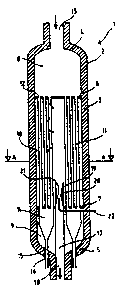
2063605 9100769 PCTABS00003
In accordance with the present invention, there is provided a
filter housing (2) comprising a plurality of open-ended parallel
hollow gas-permeable filter elements (11) for separating particulate
material from a high-temperature gas. The filter housing
comprises at least a pair of cross sectional support plates (6, 7)
dividing the filter housing into a first end section (8) having an
inlet (13) for dirty gas, a end second section (9) in connection
with a discharge port (16) for separated particulate material, and
an intermediate filtration chamber (10, 24, 24, 29, 30, 31, 41,
42) section therebetween. The filter elements are arranged in the
intermediate filtration chamber extending from the first support
plate to the second support plate. A clean gas outlet conduit (17,
26, 27, 32, 33, 34, 37, 38, 43, 44) is in communication with the
clean gas space in the intermediate filtration chamber. It is an
important feature of the present invention that means (22) are
provided inside said filter housing for supplying a reverse flow
pressure pulse of high energy gas into said filtration chamber,
for cleaning the porous filter medium. The reverse-flow pressure
pulse can be supplied through a relatively small pipe connected to
a compressor.


Claims

Note: Claims are shown in the official language in which they were submitted.


12
We claim:
1. An apparatus for separating particulate material from a
high-temperature gas, comprising:
- a vertical housing (2);
- a pair of cross sectional support plates (6, 7) having
apertures (12) therethrough and dividing said housing into
an upper end section (8), a lower end section (9) and at
least one intermediate filtration chamber (10, 24, 25, 29,
30, 40, 41) therebetween;
- an inlet (13) for gas containing entrained particulate
material in said upper end section;
- a discharge port (16) for separated particulate material
in said lower end section;
- a plurality of open-ended hollow elongated filter
elements (11) having gas-permeable side portions in said
filtration chamber (10, 24, 25, 29,:30, 31, 41, 42) affixed
at both end portions to the apertures (12) through the
support plates (6, 7), said filter elements (11) having
inlet openings (12) in communication with said upper end
section (8) and outlet openings in communication with
particle discharge elements (14, 15) in said lower end
section, and permitting gas to flow from the hollow space
inside the filter elements through the gas-permeable side
portion into said filtration chamber;
- a clean gas outlet conduit (17, 26, 27, 32, 33, 34,
37, 38, 43, 44) in communication with said filtration
chamber and
- means (22) for supplying a reverse flow pressure pulse
of cleaning gas into said filtration chamber (10, 24, 25,
29, 30, 31, 41, 42) for cleaning said filter elements,
wherein
- an inlet end (19) of the clean gas outlet conduit located
inside the filtration chamber and comprises a venturi
arrangement (20, 21) and
- a reverse pulse cleaning gas nozzle (22) is arranged in

13
coaxial alignement with the inlet end of the clean gas
outlet conduit for blowing cleaning gas into the filtration-
chamber.
2. An apparatus for separating particulate material accord-
ing to claim 1 wherein said housing (2) is a pressure-proof
upright cylindrical vessel.
3. An apparatus for separating particulate material accord-
ing to claim 1 wherein said cleaning gas nozzle (22) is
arranged to blow cleaning gas into a throat portion (21)
of the venturi ejector.
4. An apparatus for separating particulate material accord-
ing to claim 3 wherein said gas outlet conduit (17, 26,
27, 32, 33, 34, 37, 38) is disposed parallel to filter
tubes (11) in said filtration chamber.
5. An apparatus for separating particulate material accord-
ing to claim 1 wherein a clean gas outlet conduit (17, 26,
27) is arranged to pass through one of said cross sectional
support plates (7) separating the filtration chamber (10,
24, 25) and the lower end section (9) from each other.
6. An apparatus for separating particulate material accord-
ing to claim 1 wherein a clean gas outlet conduit (32, 37,
38) is arranged to pass through one of said cross sectional
support plates (6) separating the filtration chamber (29,
30) and the upper end section (8) from each other.
7. An apparatus for separating particulate material accord-
ing to claim 1 wherein said filtration chamber is divided
into at least two separate clean gas compartments (24, 25,
29, 30, 31, 41, 42) by at least one intermediate cross
sectional support plate (23, 36, 40) having apertures for
the filter elements and a clean gas outlet conduit is
disposed in each clean gas compartment.

14
8. An apparatus for separating particulate material accord-
ing to claim 7 wherein each clean gas outlet conduit (26,
27, 37, 38) is arranged to discharge clean gas from separate
clean gas compartments (24, 25, 29, 30).
9. An apparatus for separating particulate material accord-
ing to claim 7 wherein at least two clean gas outlet
conduits (26, 27, 43, 44) are combined to a common clean
gas exhaust line (28, 45).
10. An apparatus for separating particulate material accord-
ing to claim 7 wherein a clean gas outlet conduit (33)
from a clean gas compartment (30) is arranged to lead
clean gas into an adjacent clean gas compartment (29)
having a clean gas outlet conduit (32) for discharging clean
gas from the filtration chamber.
11. An apparatus for separating particulate material accord-
ing to claim 7 wherein a clean gas discharge chamber (39)
is disposed parallel to the filtration chamber being divided
into compartments (41, 42), and said clean gas outlet con-
duits (43, 44) in said compartments are arranged to lead
clean gas into said clean gas discharge chamber, and wherein
a common clean gas outlet conduit (45) is connected to
said clean gas discharge chamber for exhausting gas from
said housing.
12. An apparatus for separating particulate material accord-
ing to claim 1 wherein a clean gas outlet conduit (32, 37,
38) is arranged to pass through an upper end wall of said
housing.
13. An apparatus for separating particulate material accord-
ing to claim 1 wherein a clean gas outlet conduit (17, 28)
is arranged to pass through a lower end wall of said
housing.
14. An apparatus for separating particulate material accord-
ing to claim 1 wherein a clean gas outlet conduit (45) is

arranged to pass through a side wall of said housing.
15. An apparatus for separating particulate material accord-
ing to claim 1 wherein said filter elements comprise tubes
(11) extending between said support plates.
16. An apparatus for separating particulate material accord-
ing to claim 1 wherein said filter elements comprise
channels extending between said support plates.
17. A filtering apparatus according to claim 1 for separa-
ting solid particles from a high-temperature high-pressure
gas comprising:
- an upright cylindrical pressure vessel (12);
- an inlet port (13) for particle laden gas into said
pressure vessel;
- a clean gas outlet port (28) in said pressure vessel;
- a pair of cross sectional tube sheets (6, 7) dividing
said pressure vessel into an upper gas inlet chamber (8),
a lower end chamber (9) and an filtration chamber (10)
between said upper and lower chambers;
- a plurality of filter tubes (11) disposed between said
pair of cross sectional tube sheets arranged to combine
the gas inlet chamber with said lower end chamber;
- at least one intermediate cross sectional tube sheet
(23) disposed between said pair of cross sectional tube
sheets for supporting said filter tubes and dividing said
filtration chamber into at least two separate clean gas
compartments (24, 25) adapted to receive clean gas through
said gas-permeable filter tubes;
- an inlet end of a clean gas outlet conduit (26, 27)
protruding into each clean gas compartment (24, 25), all
clean gas conduits being arranged to lead clean gas from
the respective compartments into one common clean gas
outlet port (28) in the pressure vessel;
- a venturi (19, 20) arranged in the inlet ends of each
clean gas outlet conduit; and
- a nozzle (22) disposed in said inlet end of said clean

16
gas outlet conduits and arranged to introduce high-pressure
gas pulses into the throat (21) portion of the venturi.

Description

Note: Descriptions are shown in the official language in which they were submitted.


2 Q ~
An apparatus for separ'ating partlculate material from
high-temperature gases
FIELD OF THE INVENTION
.
S The present invention relates to an apparatus for separating
particulate material from high-temperature gases. The
present invention relates especially to a high-temperature
gas filtering apparatus comprising gas-permeable filter
elements and means for periodically cleaning the filter
10 elements.
BACKGROUND OF THE INVENTION
Modern combustion and gasification methods have resulted
15 in a need for particle separators capable of efficiently
and reliably separating particulate material from high-
temperature combustion or product gases. In circulating
fluidized bed combustion or gasification processes large
amounts af dust such as solid bed material, ashes, unburnt
20 fuel and even reactive absorbents i.e. for sulphur capture,
are continuously entrained with the exhau,sted high-tempera-
ture gases from the combustion chamber and recirculated
bac~ into the combustion chamber after having been separated
from the hot gases. The separators used have to endure
25 hot and corrosive conditions in the solids circulating
p~th without decreasing the separation efficiency or
reliability. Besides affecting the circulating fluidi~ed
bed process itself an effective separator, by removing
particulate material, minimizes' fouling of heat exchange
30 surfaces in the subse~uent gas path. '
,~' In modern combined cycle power plants, where hot combustion
~' gases are expanded in gas turbines, efficient cleaning
systems for the high-temperature gases greatly extend the
,~ :
SU BSTITUTE SH

wo gl/0076g 2 ~ 5 PCT/FI90/0017~
life and operation time of the gas turbines. Particulate
matter in hot gases greatly increase erosion and fouling
of turbine blades.
5 The present day concern with air pollution has on t~e other
hand also created a demand for efflcient dust co~lecting
apparatuses of increased capacity, even with the capabillty
of handling high-temperature gases.
10 Different kinds of particle separators for the gas cleaning
processes have been proposed and constructed to achieve
the needed reliable separation of solid particular matter
from high-temperature and often also high-pressure gases.
In recent years, gas-permeable high-temperature filters have
15 become an interesting alternative to conventional vertical
cyclone separators for separating particulate material
from these high-temperature gases. Conventional vert~cal
cyclones require substantlal space both for the cyclone
ltself and for cyclone support constructions. Filter separa-
20 tors, on the other hand, can be bullt into substantiallycompact and slmple systems. Filters made of porous super
alloys or ceramics can endure the hlgh-temperature condi-
tions and do not need to be protected by cooling surfaces
or refractory llnlngs as conventlonal cyclones have to. In
25 pressurized processes fllter separators can very easlly be
integrated into the pressurized system.
In fllter separators, dust accumulates gradually on the
surface of the porous materlal and the filter has to be
30 cleaned periodically. If large amounts of dust are allowed
to accumulate on the filter surface, a large pressure dlffe-
rence ls bullt up between both sldes of the filter and
increased pressure l.e. energy is needed for leadlng the
gas therethrough.
Filters such as bag fllters, for low temperature gases,
have been cleaned by shaklng, agltatlng, vibrating or even
brushlng or scraping therby loosening dust layers accumula-

WO 91/00769 2 t~ ~ 3 S ~i r'3 PCl`/FI90/00179
ted on the filter medium. Hlgh-temperature rigid ceramic
filters such as long, thin tube filters may be very fragile
and consequently be damaged by such rough treatment.
5 The cleaning of rigid ceramic filters is usually arranged
as reverse cleaning, by reverse flowing of clean gas through
the filter medium. During reverse cleaning the main separa-
tion process in the filter separator has to be stopped in
order to let the clean gas flow back through the filter.
10 This is, of course, a disturbance in continuous processes
exhausting large amounts of gases.
It has also been suggested to clean filter tubes by iniec-
ting compressed air pulses periodically into the tubes.
15 Compressed air operates in a pulsed manner and releases
dust from the filter tube surfaces. Each filter tube has
to have either a compressed alr in~ector of its own or a
common movable in~ector for several tubes has to be used
in order to ensure cleanlng of all filter tubes. US patent
20 4,468,240 shows a filtering separator having a filter
cleaning apparatus of the above mentioned art. The separator
has a housing dlvided into a dust laden gas space and a
clean gas space. Filter tubes are disposed ln the gas
laden space. Clean gas flows from outside lnto the filter
25 tubes and out through ~he filter tube wall lnto the clean
gas space. The cleaning of filter tubes is accomplished by
supplylng compressed air, from an ln~ector in a reciproca-
tingly displaceable chamber disposed in the clean space,
into the filter tubes, which are to be cleaned. The const-
30 ruction is very complicated and space consuming.
In US patent 4,584,003 is disclosed a filter separatorcomprising a filter housing having vertically arranged
filtratlon tubes and horizontally arranged filtration tube
35 supporters dividing the filter housing into several compart-
ments. Dust laden gas is introduced lnto the filtratlon
tubes at their upper end and separated particles are
discharged from their lower end. Clean gas flows through

2 ~ S
the porous tube walls into a clean gas space surrounding
the tubes. Each clean space has one clean gas outlet. The
filter separator is compact and simple in structure. A
cleaning method for the aforementioned filter separa~or is
5 disclosed in Japanese patent application No. 61-268330. A
diffusor is arranged in each clean gas outlet pipe outside
the filter housing. Gas from a high-pressure compressor is
introduced through the diffusor throat and the clean gas
- outlet pipe into the clean gas space. The high-pressure
10 gas jet also takes in circumferential clean gas from thè
gas outlet conduit by the ejector effect of the throat and
creates a large backwashing gas stream. The main separation
process has not to be stopped during the backwashing stage.
15 When filtering high-temperature and high-pressure gases the
diffusors in the clean gas outlet pipes become very space
consuming. The diffusors themselves are relatively large
and form long projections out to one side of the filter
separator. As the backwashing gas has to be of almost the
20 same temperature as the hot gas in the filter housing to
avoid thermal shocks on the filters, the diffusor and the
clean gas outlet pipe have to be very welI insulated, which
substantially adds to the size of the elements projecting
out from the filter housing. This makes the otherwise
25 compact filter housing less attractive from constructional
point of view.
OBJECT OF THE INVENTION
30 It is an object of the present invention to minimize the
drawbacks of the known filter surface cleaning systems. It
is another object of the invention to provide a filter
cleaning system which can be utilized without disturbance
to the separation operation. It is further an ob;ect of
35 the invention to provide a compact and simple filter
separator for high temperature gas cleaning purposes. It
is still further an object of the present invention to
pro~ide an easily modulated apparatus for separating
S~ TI~U~ SH~

WO 91tO0769 2 o ~ 3 ~tFI90~00l79
particulate material from high temperature gases.
~'
SUMMARY OF THE INVENTION
5 In accordance with the present inventlon, there is provided
a filter housing comprising a plurality of open-ended
parallel hollow gas permeable fllter elements for separa-
t~ng particulate materlal from a high-temperature gas. The
filter housing comprises at least a pair of cross sectional
10 support plates havlng apertures therethrough, for dividing
the fllter housing lnto at least three sections and for
supporting the filter elements. The support plates divide
the filter housing into a first end section having an inlet
for dlrty gas, a second end sectlon ln connectlon with a
15 discharge port for separated partlculate materlal and an
intermediate filtration chamber section therebetween. The
- filter elements are arranged ln the intermediate f$1tration
chamber extendlng from the first support plate to the
second support plate. The end portlons of the hollow gas-
20 permeable fllter elements are affixed to the apertures
through the support plates. The gas-permeable filter
elements permit clean gas to flow from the hollow space
inside the filter elements through the gas-permeable side
portion into the clean gas space in the intermediate
25 flltration chamber. Inlet openings Qf the filter elements
are arranged in communication wlth the first end sectlon
of the filter-housing, for introduclng dlrty gas lnto the
filtration elements. Outlet openings of the filter elements
are in communication with the second end section, for
30 discharging separated particulate material from the filter
elements. A clean gas outlet conduit ls in communication
wlth the clean gas space in the intermedlate flltration
chamber, for discharglng clean gas from the filter houslng.
It ls an important feature of the present inventlon that
35 means are provided inside sald filter housing for supplylng
a reverse flow pressure pulse of high energy gas into sald
flltration chamber, for cleaning the porous fllter medium.
The reverse-flow pressure pulse can be supplied through a

WO91/00769 PCT/FI9~/00179
2 ~ ~ 3 ~ ~ ~ 6
relatively small pipe connected to a compressor.
The present invention is especlally suitable for filter
separators in pressurized systems. The cleaning system can
5 advantageously be built in vertical, cylindrical pressure-
proof filter houslngs~ `
Cleaning gas pulse ~ets are preferably arranged in com-
munication with clean gas outlet conduits ln the lnlet
10 end of the conduits. The cleaning gas may be fed through
gas nozzles arranged in coaxial allgnement with the inlet
ends of the clean gas outlet conduits. For preventing the
high-pressure cleaning gas pulses from entering into the
clean gas outlet conduits, there are arranged e~ector means
15 inside the inlet means of the clean gas outlet condults.
As the cleaning gas pulse is blown lnto the e~ector throat,
a plug of gas is formed in the throat preventing clean gas
from leaking out. The gas pulse is very short and does not
disturb the overall separation process.
The inlet end of the clean gas outlet conduit containing
the e~ector may be arranged to extend lnto the clean gas
space in the filtration chamber. According ta one embodiment
of the invention, the clean gas conduit is arranged paral-
25 lel to the longitudinal direction of the filtration ele-
ments. The clean gas outlet may be arranged to pass out
from the flltration chamber either through an upper first
end section or through a lower second end sectlon and then
through the end wall out from the filter housing.
According to the inventlon, there may;be addittonal lnterme-
diate cross sectional support plates in the filtration
- chamber to divlde the chamber lnto two or more clean gas
compartments. Each compartment may have its own clean gas
35 outlet conduit and cleanlng gas nozzles.
The clean gas conduits from the separate compartments may
have separate outlet ports through the filter housing wall

2 ~ ~ 3 ~ ~3 5
or may preferably be combined so that the gases are dischar-
ged through one common gas outlet port. In pressurized
systems it is advantageous to arrange as small and as few
ports through the pressure vessel wall as possible. The
5 clean gas outlet conduits can according to a further
embodiment of the present in~ention be arranged to lead
clean gas from one clean gas compartment into the next
adjacent clean gas compartment and finally out through
either end section and corresponding end wall.
According to still another embodiment of the present
invention there is provided a separate clean gas discharge
chamber adJacent the filtration chamber. Clean gas outlet
conduits are arranged to lead from each clean gas compart-
15 ments into the common clean gas discharge chamber. Theremay then be only one clean gas outlet port in the surroun-
ding filter housing. The clean gas discharge chamber may
be, for example, arranged in a vertical cylindrical pressure
vessel parallel to an upright filtration chamber and
20 extending from an upper filter tube support plate to a
lower sup~ort plate. Only a clean gas outlet port may then
be needed in the cylindrical side wall of the pressure
vessel.
25 The filter elements used in an apparatus according to the
present invention may be filter tubes or elements forming
filtration channels therebetween. The filter elements may
be made of porous ceramic materials or super alloys.
30 The present invention provides a smaller and more compact
particle separation system without protruding (voluminous)
large insulated outlet ports or diffusor arrangements.
There is no need to lea~e space outside the filter ~essel
itself for these protruding elements or support construc-
35 tions they would need. The filter housing itself may besomewhat bigger but it can easily be taken into considerati-
on when constructing filtering systems and the systems can
easily be modulated and the filter systems can be more

WO91/00769 PCT/F190/00179
20~3t~ 8
easily predimensioned and predeslgned.
The present invention thus provides an improved design of
a filter module. Previous designs have had multlple vessel
5 exits coming from the side of the pressure vessel. According
to the present invention the filter module can be designed
with even only one gas exit from the bottom, top or si~e of
the vessel. Especially ln pressurized systems, and hot
systems all expansion Joints between the main filter housing
l0 and any outlet ports are weak points in the systems and
therefore the number of outlet or inlet ports should be
kept at a minimum.
Only one exit in the bottom of the vessel can be accom-
15 plished by arranging filter tubes in an annular pattern in
the filtration chamber and the clean gas outlet conduit
comprising the cleaning e~ector in the center of the
filtration chamber. Center outlet from multiple compart-
ments is accomplished by splitting the clean gas outlet
20 conduit lnto as many branches as there are compartments
and routing all of the branches through the lowest compart-
ment in the bottom or through the lower end section of the
filter housing. All except one clean gas outlet condult
branch is then led through the next compartment above and
25 so forth. Fly ash may be collected in multiple hoppers at
the bottom end section and discharged through a pipe at the
bottom of each- hopper.
A more compact arrangement can thus be achieved and a single
30 connection-for clean, hot flue gas outlet. The assembly
and lnspection of the filter housing is also made much
easier.
BRIEF DESCRIPTION OF THE DRAWING FIGURES
FIG. l shows a schematic vertical cross-sectional view of
a fllterlng separator according to the present invention;
FIG. 2 shows a cross-sectional view thereof along llne A-A:

WO91/00769 2 ~ ~ ~ ?~ ~ 5 PCT/Fl90/00179
FIG. 3, 5, 7 and 9 show schematic vertical cross-~ectional
views similar to FIG.1 illustrating other embodiments of
the present invention;
FIG. 4, 6, 8 and 10 show cross-sectional views of them
5 along lines A-A;
DETAILED DESCRIPTION OF PREFERRED EMBODIMENTS
Referring now to the drawings, identical parts are marked
10 by identical refrence symbols ln all embodiments.
In FIG. 1 there is illustrated a filter separator 1 comp-
rising a substantially vertical cy~lndrical filter housing
2. The filter housing has lnsulated side walls 3 and upper
15 and lower end walls 4 and 5. The filter housing is divided
by two support plates or tube sheets 6 and 7 into three
sections, a first upper end section 8, a second lower end
section 9 and an intermediate section or filtration chamber
10 .
Openended hollow filter tubes 11 are arranged in the
filtration chamber 10 to extend from the upper support
plate to the lower support plate. The filter tubes are
affixed to openings 12 in the upper and lower support
25 plates, thus connectlng the space in the upper end section
with the space in the lower end section. In the upper end
section there is disposed a dirty gas inlet 13 through
which gas contalnlng particulate matter can be introduced
lnto the filter separator. Clean gas flows from inslde the
30 hollow f~lter tubes 11 through the tube walls into the
clean gas space in the filtratlon chamber lO. Particles
are detained lnslde the filter tubes. In the lower end
sectlon hoppers 14 are dlsposed below openlngs connected
to filter tubes. The hoppers collect particulate material
35 separated from the dirty gas ln the filter tubes. The
hoppers have dlscharge plpes 15 connected to their bottoms,
for discharging collected particles out from the filter
housing through small openings 16 arranged in the lower

2~3~S
end wall 5.
- In the center of t~e lower support plate 7 a clean gas
outlet conduit 17 is arranged to extend into the filtration
5 chamber lO. The clean gas outlet conduit is further arranged
to pass through the lower end section 9 and through an
opening 18 in the lower end wall 5.
The inlet end 19 of the clean gas outlet conduit 17 is
10 formed as an ejector 20 having a throat 21. A relatively
small pipe 22 is disposed in the clean gas outlet conduit
for supplying a pulse of high pressure gas through the
ejector 20 into the filtration chamber. The high pressure
gas jet causes backflow of gas through the filter tube
15 walls and loosens dust accumulated on the inner walls of
the filter tubes.
FIG. 2 i}lustrates a cross-sectional ~iew of the above
described separator taken along line A-A. The clean gas !,'
20 outlet conduit 17 is disposed in the middle of the housing
2 and the filter tubes ll are disposed annularly around
the conduit. '
FIG. 3 and 4 illustrate another embodiment of the present
25 invention. A intermediate support plate 23 is disposed in
the filtration chamber 10 to support the filter tubes. The
support plate divides the chamber 10 into two separate
clean gas compartments 24 and 25. Each compartment has a
separate clean gas outlet conduit 26 and 27 extending
30 downwards into the lower end section 9 of the filter
housing. The conduits 26 and 27 are combined to one common
outlet conduit 28. By combining the clean gas outlet
~, conduits only one outlet opening for clean gas is needed in
the filter housing wall, which simplifies the construction
i 35 considerably.
FIG. S and 6 show still another embodiment of the present
in~ention. The filtration chamber is divided by two interme-

WO91/00769 PCT/FI90/00179
11 2~6~5
diate support plates into three separate compartments 29,30 and 31 each compartment havlng a clean gas outlet conduit
32, 33 and 34. The clean gas conduit 34 from compartment
31 leads gas into the ad~acent compartment 30 and the clean
5 gas conduit 33 leads gas from compartment 30 into~compart-
ment 29. The clean gas is discharged from the filtration
chamber through conduit 32 which passes through the upper
end wall 4 through an opening 35.
10 F~G. 7 and 8 show a filter housing having the filtration
chamber 10 divided by a support plate into compartments
and having separate clean gas outlet co~duits 37 and 38
arranged in each compartment. The outlet conduits pass
according to this embodiment through separate openings in
15 the upper end wall out from the filter housing. In the
upper end wall it is more easy to arrange outlet ports
than in the cylindrical side wall 3.
F-,. 9 and 10 show an embodiment of the present invention
20 according to which a clean gas chamber 39 is arranged
vertically parallel to the flltration chamber 10. The
- filtratlon chamber is divided by a support plate 40 into
separate compartments 41 and 42. Both compartments have
clean gas outlet condults 43 and 44 arranged to dlscharge
25 gas into the clean gas chamber 39. There is a clean gas
outlet port 45 arranged in the cylindrical slde wall 3.
This embodiment ca be advantageous if there is little or
no space around the upper and lower ends of the filter
housing to arrange clean gas outlets. There is still only
30 one clean gas outlet and no space consuming diffusors.

Representative Drawing
A single figure which represents the drawing illustrating the invention.
Administrative Status

2024-08-01:As part of the Next Generation Patents (NGP) transition, the Canadian Patents Database (CPD) now contains a more detailed Event History, which replicates the Event Log of our new back-office solution.

Please note that "Inactive:" events refers to events no longer in use in our new back-office solution.

For a clearer understanding of the status of the application/patent presented on this page, the site Disclaimer , as well as the definitions for Patent , Event History , Maintenance Fee  and Payment History  should be consulted.

Event History

Description Date
Inactive: IPC from MCD 2006-03-11
Time Limit for Reversal Expired 2000-07-06
Letter Sent 1999-07-06
Grant by Issuance 1993-10-26
Request for Examination Requirements Determined Compliant 1992-01-10
All Requirements for Examination Determined Compliant 1992-01-10
Application Published (Open to Public Inspection) 1991-01-13

Abandonment History

There is no abandonment history.

Fee History

Fee Type Anniversary Year Due Date Paid Date
MF (patent, 7th anniv.) - standard 1997-07-07 1997-06-16
MF (patent, 8th anniv.) - standard 1998-07-06 1998-06-15
Owners on Record

Note: Records showing the ownership history in alphabetical order.

Current Owners on Record
FOSTER WHEELER ENERGIA OY
Past Owners on Record
DAVE B. RUSSELL
JUHANI ISAKSSON
Past Owners that do not appear in the "Owners on Record" listing will appear in other documentation within the application.
Documents

To view selected files, please enter reCAPTCHA code :


To view images, click a link in the Document Description column. To download the documents, select one or more checkboxes in the first column and then click the "Download Selected in PDF format (Zip Archive)" or the "Download Selected as Single PDF" button.

List of published and non-published patent-specific documents on the CPD .

If you have any difficulty accessing content, you can call the Client Service Centre at 1-866-997-1936 or send them an e-mail at CIPO Client Service Centre.


Document
Description 
Date
(yyyy-mm-dd) 
Number of pages   Size of Image (KB) 
Drawings 1997-10-27 5 144
Claims 1997-10-27 5 241
Abstract 1997-10-27 1 60
Descriptions 1997-10-27 11 608
Representative drawing 1998-12-17 1 8
Maintenance Fee Notice 1999-08-02 1 179
Fees 1996-06-11 1 78
Fees 1993-06-21 1 35
Fees 1995-06-13 1 43
Fees 1994-06-12 1 212
Fees 1992-06-21 1 35
PCT Correspondence 1993-08-10 1 24
Courtesy - Office Letter 1992-11-04 1 32
International preliminary examination report 1992-01-09 17 592
Courtesy - Office Letter 1992-10-01 1 54