Note: Descriptions are shown in the official language in which they were submitted.
2~3961
PHA 21.661 1 10.03.1992
High pressure gas discharge lamp.
This invention relates to a high pressure gas discharge larnp and
particularly to a high pressure sodium vapor lamp, comprising an arc tube; first and
second electrodes disposed in said arc tube; vaporizable materials disposed within said
tube, which during operation provide a vapor through which current will flow between
5 said electrodes.
~ Iigh Pressure Sodium Lamps (HPS) exhibit a wide lamp voltage range,
regardless of the lamp wattage. This voltage range (or spread) typically is i B volts for
10 low-voltage larnps, + lS volts for high voltage lamps, and up to ~ 35 volts for
1000 W HPS lamps. One of the consequences of this spread in lamp voltage is thatduring operation, the larnp wattage also has a corresponding spread.
Quite aside ~rom the undesirability of too large a spread in lamp voltage
from the nominal, the consequences of which could be hannful to larnp quality and life,
15 this voltage spread also represents aspects of spread of larnp manufacturing. Therefore,
a method of reduction of the voltage spread is important from lamp quality point of
view and thus from manufacturing point of view.
Lamp voltage spread ~in HPS lamps) can be ascnbed primarily to a single
factor (for the purpose of this application we assume that all measurements are made on
20 a reference ballast, thus eliminating the voltage vanation due to ballast variations):
spread of cold spot or amalgam temperature from lamp to lamp. This is true for the
lamp wa~tages currently in production (the so called saturated HPS lamps). For each of
these lamps it holds that there can always be found in the coldest parts of the operating
lamp (called the "cold spotN), a quantity of condensed amalgam of sodium (Na) and
25 Mercury (H~). The amount (mass) and mole fraction of this amalgam is controlled by
the temperature of the cold spot. The temperature of the cold spot controls the vapor
pressure of Na and Hg for a given lamp, the dependence of the vapor pressure on cold
spot temperature is exponential. Thus minor difference in this temperature have
206396~
PHA 21.~61 2 10.03.1992
profound effects on the quantities of Na and Hg that may be found in the vapor state.
The lamp voltage is primarily dependent on the vapor pressure of these two species.
Thus it is evident that the lamp voltage spread is directly related and primarily due to
temperature spread of the cold spot between copies of one type of lamp.
The spread of cold spot temperature is due to several factors for a given
lamp type. Some of the important parameters are: spread and variations in PCA
(polycrystalline alumina~ arc tube wall thickness, in diameter of the PCA arc tube, in
electrode construction (i.e. thermal contact between coil and rod), in composition and
distribution of electrode emitter, in scrape height (i.e. the electrodes distance), etc. It is
10 possible that more heat is conducted to the cold spot of the lamp for a thin walled arc-
tube than for the thick walled arc-tube. Approximately 38% of the input energy to a
HPS lamp is lost by heat conduction through the PCA wall of the arc-tube. Duringmanufacturing of PCA tubes, spread and variations in wall thickness of ~ 0.2 mm are
typical. Combining the three items, being effect of wall thickness on wall temperature
15 heat loss through the PCA wall, and manufacturing variability of PCA wall thickness, it
is likely that spread and variations in wall thiclmess can play an important role in
influencing the spread of amalgam temperature. Naturally, the obvious approach is to
attempt to minimize spread and variations in the important parameters. At some point~
the manufacturing capability and economics may put a limit to what can be achieved
20 with this approach.
The actual value of the cold spot temperature is determined by an energy
balance, between conducted heat as input, and primarily radiated power as output. Heat
is lost by radiation through emission of infra-red radiadon. The spectral emissivity of
PCA is 0.2 - 0.3. See in this regard the treatise "The High Pressure Sodium Lamp", de
25 Groot and Van Vliet, Philips Technical Library 1986. The power loss by this means is
described by the equation:
P = CT
where C is the emissivity, and T is the temperature of the radiator. Accordingly, a
dif~erent value for the emissivity of the arc tube will result in a different value for the
30 cold spot temperature.
The invention has for its object amongst othas to provide a measure as to
2063961
PHA 21.661 3 10.03.1992
effectively reduce the spread in lamp voltage occurring between individual copies of the
lamp as defined in the preamble.
According to the invention a high-pressure discharge lamp of the kind
described in the preamble is characterized in that a high emissivity coating is disposed
S at least on one end of the arc tube proximate to at least one of the electrodes, said
coating being the outermost layer of coating on said arc tube end to increase the
radiative emissivity of said tube of its location and thereby cool the cold spot of said arc
tube.
Certain prior lamp designs have utilized coatings disposed proximate to
10 the electrodes or the cold spot of high pressure gas discharge lamps to alter their
performance. Such coatings have generally been directed towards increasing the cold
spot temperature so as to increase the efficiency or improve colour properties of the
lamp. For example, see U.S. Patent 3,842,304 to Beyer et al, issued October 15, 1974
in which a two layer coating is applied to a high pressure gas discharge lamp so as to
15 increase the cold spot temperature. In this patent, the outermost coating is that of a
white material which serves to lower the emissivity, of the cold spot and thus increase
its temperature. It is noted that an inner coating of carbon material i9 used for its high
thermal radiation absolption properties.
The present invention however is directed to coating a section of the PCA
20 wall near the cold-spot region with a substance of higher emissivity as to effect a
reduction in cold spot temperature. It has occurred to the inventors that this measure
effectively reduces the spread in lamp voltage between individual copies of the lamp.
This advantageous effect is most probably due to the fact that as soon as the affected
region will acquire a higher temperature as a result of an increase of heat input (e.g. by
25 conduction), the power lost by radiation will correspondingly increase and thus
effectively counteract the actual temperature increase. In summary, it has been
- established that coating the PCA with a substance of relative high emissivity will act as
a temperature regulator, superior to such regulation as might exist with PCA alone, by
virtue of enhanced radiation. A suitable material for increasing this radiated heat loss is
30 graphite, with spectral emissivity between 0.9 - 0.95.
The present invention is directed towards decreasing the cold spot
temperature so as to rninimize the lam~to-larnp spread between individual lamps of the
same nominal wattage. The invention permits manufacture of lamps within tighter
20639fil
PHA 21.661 4 10.03.1992
voltage tolerances than have hitherto been achieved. The decrease in cold spot
temperature may result in a lower actual lamp voltage and thus in some loss in larnp
efficiency, however, this may be compensated for by increasing the electrode distance
to raise the actual voltage of the lamp. Furthermore, it has been found that the present
5 invention decreases the "fixture effect". This effect occurs when the mounting of the
lamp within various fixtures causes changes in the lamp voltage. Lamps produced in
accordance with the present invention display less of a fixture effect than that of
previous lamps.
For better understanding of the invention, reference is made to the
following drawings which are to be taken in conjunction with the detailed specification
to follow:
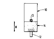
Figure 1 is a drawing of the end of a high pressure gas discharge larnp
15 arc tube with the high emissivity coating applied as an annular band;
Figure 2 shows the end of the arc tube with the high emissivity coating
applied as a strip at the end of the lamp; and
Figure 3 is a graph of lamp voltage versus height of the graphite coating
on the lamp.
Figure 1 illustrates a first configuration of the invention. Shown in
Figure 1 is the end of an arc tube 10 which may be in the form of a polycrystalline
alumina tube or other suitable material for a high pressure gas discharge arc tube.
25 Extending from the end of arc tube 10 is a niobium tube 12 which makes electrical
contact with the electrode 14. This portion of the PCA tube 10 is generally constituting
the cold spot. Applied to the end of tube 10 is an annular coating of graphite which
serves to increase the thermal emissivity of the arc tube 10 to thereby further cool the
cold spot. As is set forth in the experimental results to follow, this provides a reduction
30 in the voltage spread between individual copies of the lamp. The graphite coating 14
was applied by means of a suspension of powdered graphite material in a liquid carrier
such as water into which the end of arc tube 10 is dipped. The coating could also be
brushed or sprayed on.
2063~61
PHA 21.661 5 10.03.1992
The coating as shown in Fig. 1 was applied to 1000 Watt and 400 Watt
high pressure sodium lamps. Production samples of lamp copies of these wattages were
obtained, and the stabilized lamp voltage for each copie of each sample was measured~
using a reference ballast. The measurements were made with no coating on the arc-tube,
5 and then with a thin layer of graphite 14 applied to the end region of the PCA arc-tube
10 in the manner shown in Fig. 1. All arc-tubes had identical application of graphite
with respect to height H and thickness of layer. In Table I and Table II are presented
the stabilized lamp voltages without and with graphite coating. It should be noted that
the arc tubes in the lamps shown are the same. The only difference is the application of
10 the graphite coating.
TABLE I
1000 Watt HPS Lamp
Stabilized Lamp Vol
Arc Tube ~Without Graphite With Graphite
_ Coating H = 15 mm
Al 297.6 207.6
A2 292.4 200.2
A3 271.3 204.1
A4 255.2 199.2
A5 301.3 207.2
.
Avg. 283.6 203.7
s.d. 19.7 3.8
206396~
PHA 21.661 ~ 10.03.1992
TABLE 1~
400 Watt HPS Lamp
1 11
Stabilized Lamp Volts
5 l Arc Tube # Without &raphite With Graphite
¦ Coating H = 9 mm
Bl 100.3 78.8
B2 122.5 90.8
B3 111.7 80.7
_ _ ~
It is evident from these tests that the standard deviations (s.d. in the
Tables) for both groups of lamps tested shows a significant reduction in value, implying
that the lamp voltage spread has been effecdvely and significantly reduced. The actual
value of the lamp voltage is also reduced, but this is not a major concern. The actual
lamp voltage may be raised to its original nominal value by increasing the electrode
15 distance, for instance by decreasing the scrape height.
Figure 2 illustrates another configuration of the application of a graphite
coating. In this application, the graphite coating is applied in a strip 16 which does not
extend around the arc tube 10. In each case, the coating is applied to a height H. In
further measurements, the height H of the strip was varied and thus the total surface
20 area of the graphite coating 14 was also varied. The results of these measurements are
as follows.
206396~
PHA 21.661 ? 10.03.1992
amp Type: 400
Lamp # Coating Area Lamp Volts Lamp Volts ,~V/A
-- - (mm2) (No Ctg.) (With Ctg.) (Volt/mm2)
A-1 46.6 100.3 82.3 -0.39
A-2 72.4 111.1 85 .0 -0.36
A-3 106.5 122.5 81.0 -0.39
It is seen in the last column that in each case, there is a reduction in lamp voltage which
is proportional to the surface area of the applied coating. The thus formed
proportionality factor can be regarded to be constant for this mode of application.
10 Accordingly, a coating applied in this manner would also be successful in cooling the
cold spot and thus providing a reduction in lamp voltage spread.
Figure 3 illustrates the dependence of lamp voltage (V~) versus the height
(H~ of the coating applied in the form of a ring as in Figure 1. As the height of the
coating increases, and thus its surface area becomes larger, there is first a decrease in
15 lamp voltage but after a certain height is reached lamp voltage thereafter begins to
increase again. Thus, there is a preferable coating height (i.e. the coating height
providing the largest decrease in lamp voltage) for each type of lamp and graphs such
as Figure 3 can be used to calculate optimum height.
As a coating material any material which has a higher emissivity than the
20 arc tube may be used. However, graphite has one of the highest emissivities, is
inexpensive, and is easily applied so that its use is preferred. The coating may be
applied to one or both ends of the arc tube. However, since the high emissivity coating
"forces" the cold spot to be at its location, coating any one end is generally only
necessary.
The particular embodiments disclosed in detail herein and discussed
above are merely illustrative of the principles of this invention. Numerous modifications
and adaptions thereof will be readily apparent to those skilled in the art without
departing from the spirit and scope of this invention.