Note: Descriptions are shown in the official language in which they were submitted.
wo 91/04372 ( 1 ) 2 û;6 4 0 4 3 Pcr/usgo/02728
PATENT APPLICATION
COUCH PRESS TRANSFER APPARATUS AND METHOD
BACKGROUND OF THE INVENTION
This invention relates to the transfer of a paper web
from the forming section to the press section in a
papermaking machine. More particularly, this invention
relates to the transfer of a paper web from a forming fabric
to a pick-up felt in conjunction with further dewatering of
the web. Still more particularly, this invention relates to
the transfer of a paper web from a forming fabric over a
vacuum zone on a couch roll which is effected by the nipping
engagement of a pick-up felt against the web by a transfer
roll which is also equipped with a vacuum zone.
In modern paperm~king machines, the transfer of the
paper web from the forming section to the press section must
always be effected positively, that is, the paper web must
always be carried on the surface of a forming fabric or a
pick-up fabric, in order to prevent web breakage at high
papermaking speeds. Prior web pick-up arrangements have
utilized bringing a pick-up felt into engagement with the
web over a span of the forming fabric between a couch roll
an a fabric turning roll. In fourdrinier-type forming
arrangements, the couch roll defines the end of the
generally horizontal forming section at which point the
fabric is directed downwardly with the web on its surface,
and it is in this downwardly extending portion of fabric
travel that the transfer is effected. A typical such
arrangement is shown in Wicks et al, U.S. Patent No.
4,483,745.
It has also been common practice to pick,the freshly
formed paper web off the forming fabric by bringing a
pick-up fabric, such as a felt, into nipping engagement with
the web over a roll within the forming fabric, such as the
couch roll or the fabric turning roll. Such an arrangement
is shown in Wahlstrom et al, U.S. Patent No. 3,671,389.
wO 91/04372 (2/~) ~0~4043 pCT/lT~/n)728
These arrangements are adequate and wor~ well at
papermaking speeds below about 1100 meters per minute, or
with ade~uately dried webs capable of withstanding a
relatively high vacuum pressure in the transfer roll, or-
with relatively heavy paper webs, or with some combination
of all of these parameters.
In GB-A-602237, a web pick-up arrangement is shown
wherein the web is partially dewatered and transferred from
the couch to a pick-up roll, but the trailing seal ln the
couch roll is not positioned downstream of where the forming
fabric and web leave the couch roll. Further, the leading
seal of the pick-up roll is not positioned downstream of the
nip between the couch and pick-up rolls.
In many modern papermaking machines, the web is formed
between two, co-running forming fabrics which produce
superior paper formation and more uniform fines and fillers
distribution which provides a higher quality paper product.
One sheet characteristic which has not always improved in
such two-fabric paper web forming apparatus is the dryness
of the web leaving the forming section and guided into the
press section. The more relatively wet the paper web is,
the greater the chance of its breaking, especially at the
critical point of its removal from the forming fabric and
transfer into the press section.
SUMMARY OF THE INVENTION
This invention provides for both additional dewatering
of the web while it is still being carried by the forming
fabric, while at the same time providing for a positive
transfer of the web onto a pick-up felt which conveys it
directly into the first press nip. Thus, this invention is
especially suitable for the transfer of a web from a
secondary couch roll in a two-fabric papermaking apparatus.
In this invention, the web is first subjected to
additional dewatering pressure by carrying the web over a
vacuum zone on the couch roll immediately prior to a nip
206~043
WO 91/04372 (2/B) PCT/ITSYn/~'728
with a transfer roll. The nip expresses, or urges,
additional water into the couch roll through the couch roll
vacuum zone. Further, the forming fabric on which the web
is being carried, wraps the web onto the pick-up felt over
an arcuate portion of the periphery of the transfer roll
downstream of the nip to guide the web away from the couch
roll and thereby min;mi ze rewetting by water flung outwardly
through the holes in the couch roll shell coming off the
WO91/04372 (3) 2 0 6 4 ~ 4 3 PCT/US90/02728
vacuum zone. This improves web dryness. These functions
all occur prior to, or during, the actual transfer of the
web from the forming fabric onto the pick-up felt. Most of
the so-called "white water" , as the water in the forming
section of a paperr~k;ng m~ch;ne is called by papermakers,
is thus removed in the forming section through the forming
fabric, thereby min;m;zing cont~min~tion of the pick-up felt
with fines and fillers.
Downstream of the arcuate portion of the transfer roll
surface wrapped by the forming fabric is a vacuum zone which
functions to both encourage transfer of the web onto the
felt from the forming fabric and to maintain it there after
transfer. The relatively greater permeability of the
forming fabric compared with that of the pick-up felt
proAllc~s a greater affinity of the web for the pick-up felt
before the web is subjected to the vacuum zone pressure over
the transfer roll.
Accordingly, it is an object of this invention to
provide for a positive transfer of a paper web from a
forming fabric onto a pick-up felt in a paperm~k;ng machine.
It is another object of this invention to provide a
combination web dewatering nip and web transfer between a
forming fabric and pick-up felt in a papermaking machine.
Another object of this invention is to provide a paper
web transfer apparatus and method which is especially
suitable for transferring relatively wet paper webs from the
forming section to the press section in a papermaking
machine.
Still another object of this invention is to provide a
method and apparatus for improving the web dryness of a
paper web, particularly one formed on a two-fabric
paperm~k;ng machine, going into the first press nip.
W091/~372 ~ (4) PCT/US90/02728
206~0~3
Still another object of this invention is to enhAnre
white water removal in the forming section, thereby
m;nim; zing contAm;nAtion of the pick-up felt.
A feature of this invention is the provision of the
application of a vacuum zone in the transfer roll which
begins after the nip with the couch roll.
These and other objects, features and advantages of
this invention wiil become more readily apparent to those
skilled in the art upon reading the description of the
preferred PmhoA;m~nt in conjunction with the attached
drawings.
IN THE DRAWINGS
Figure 1 is a side-elevational view of a two-fabric
papermaking mAch;ne which illustrates the couch press and
transfer apparatus of this invention as well as the press
section of a papermaking machine.
Figure 2 is a side-elevational view, with partial
broken away sections, of the paper web dewatering and
transfer apparatus shown in figure 1.
DESCRIPTION OF THE ~ ~KK~ E~30DIMENT
As shown in figure 1, a heA~hox 10 projects a dilute,
aqueous slurry of wood pulp fibers, commonly known as stock,
into a converging throat 12 formed between first and second
looped forming fabrics 14,16 which are guided around a
corresponding pair of breast rolls 18,20 and are directed
into co-running travel on either side of the stock slurry
over a series of vertically arrayed dewatering elements 22,
24 and 26 which serve to guide the forming fabrics in a
gently curing, substantially vertically arrayed path of
travel upwardly over a first couch roll 28. Water is
withdrawn inwardly through the foraminous surface of first
couch roll 28 over a forming zone which is defined by a
suction box within the roll having upstream and downstream
seals 30,32, respectively. Downstream of the first couch
WO gl/04372 ~ ( 5 ) 2 0 6 4 0 1 3 Pcr/us9o/o2728
`
roll 28, the first forming fabric 14 is directed away from
the web W travelling on the second forming fabric 16 as the
first fabric 14 travels over a tail roll 34. A foil 36
serves to remove free water travelling on the underside of
the second forming fabric 16.
The second forming fabric 16, having the web W carried
on its surface, then travels downwardly over a secondary
couch roll 38 where it is transferred to a looped pick-up
felt F-P which also functions as a first press felt. The
web W re--;ne on the underside of the pick-up/press felt F-P
through the first press nip N-l between first (suction) and
second (grooved) press rolls 40,42. A lower press felt F-L
is directed into co-running engagement with the web and
pick-up felt for travel through the first press nip N-l.
The web is retAine~ on the first press felt F-P and
subsequently travels through a second press nip N-2 between
a second pair of press rolls 44,46. The web W, having a
greater affinity for the smooth, impervious surface of press
roll 46, transfers from the pick-up/press felt F-P to the
surface of the press roll 46 where it proceeds through the
remainder of the press section and through the remAining
downstream sections of the papermaking machine. Another
press roll 47 and an upper felt F-U form a third nip N-3
with the web. A plurality of felt guide rolls 48 guide the
felts F-P, F-L, F-U in their looped paths of travel.
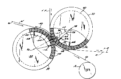
Figure 2 illustrates the invention residing in the
couch dewatering press and web transfer more clearly. The
web W carried on forming fabric 16 is conveyed onto the
foraminous surface of couch roll 38. The construction of
couch rolls is well-known in the paper~Aking industry, so
the details of the individual elements, such as the internal
suction box, the manner in which a source of vacuum is
applied to the suction box through the end of the roll to
provide the vacuum pressure, and the size and type of holes,
or openings, through the roll shell 39 forming the
foraminous surface of the roll shell will not be discussed
further.
W O 91/04372 (6) 2064043 PC~r/US90/02728
The suction box providing vacuum pressure within the
couch roll 38 is defined by upstream (leading) and
downstream (trailing) seals 50,52, respectively, as well as
end seals (not shown). A multitude of small holes 54 are
drilled through the roll shell to provide a means to receive
water from the web W, through forming fabric 16 and into the
suction box 58. The arcuate area on the roll surface over
the leading and trailing seals 50,52 is known as a vacuum
zone 56.
A transfer roll 60, having a construction similar to
couch roll 38, is disposed opposite couch roll 38 and guides
pick-up/press felt F-P into nipping engagement with the web
W on forming fabric 16 over the couch roll 38 in a nip N-P
as the forming fabric 16 travels to turning roll 19. The
transfer roll also has an internal suction box 62 defined by
upstream (leading) and downstream (trailing) seals 64,66
which subtend a vacuum zone 68 over the surface of the roll
shell 70 which has a plurality of small holes 72 drilled in
it to permit vacuum pressure to be applied to the vacuum
zone 68 on its roll surface.
The leading seal 50 extends upstream of a line 74 drawn
between the axes of revolution 76,78 of couch roll 38 and
transfer roll 60, respectively, and through nip N-P.
Similarly, the trailing seal 52 of couch roll 38 extends
downstream of line 74 exten~;ng between the axes 76,78. The
arrows show the direction of forming fabric and felt travel.
In a similar ~Ann~r ~ both 1~A~; ng and trailing seals
64,66 in transfer roll 60 are downstream of line 74 through
axes 76,78 and nip N-P.
In operation, the web W travelling on forming fabric 16
comes into vacuum zone 56 over the couch roll 38 where it is
exposed to additional dewatering vacuum pressure and the
white water is urged primarily into couch roll 38. Pick-up
felt F-P is brought into nipping engagement N-P with the top
wo 91/04372 ( ~ 2 0 6 ~ O ~ 3 Pcr/usgo/02728
surface of web W by transfer roll 60 over couch roll 38.
T~m~Ai ately downstream of nip N-P, forming fabric 16 wraps
the web W and felt F-P over the surface of transfer roll 60
over an arcuate segment defined by angle extending
between line 74 and a radial line 75 between the axis of
rotation 78 of the transfer roll to where fabric 16 leaves
the transfer roll.
The belt pressure of the forming fabric 16 held over
the arcuate segment of the transfer roll subtended by angle
, in combination with the greater affinity of the web
web for the relatively more dense surface of pick-up felt
F-P, compared with the interstices in the surface of forming
fabric 16, combine to transfer the web onto the pick-up felt
F-P. At a point over vacuum zone 68 on transfer roll 60,
the forming fabric 16 is guided away from the web W, which
is simultaneously exposed to the vacuum pressure over vacuum
zone 68 on the surface of the transfer roll to maintain the
web on the felt. The web W is then guided into the press
section by being adhered to the underside of felt F-P.
The trailing seal 52 in couch roll 38 defines a small
arcuate portion 57 of the vacuum zone 56 downstream of nip
N-P. This serves to urge water expressed from the web
through the interstices of forming fabric 16 either through
the foraminous surface of the roll shell 39 of the couch
roll or downwardly and away from forming fabric 16. Either
way, this action in conjunction with the forming fabric
wrapping the web over the transfer roll prevents rewetting
of the web.
Thus, the web is dewatered before and during its pass
through nip N-P. Water on the top side of the web is
received into pick-up felt F-P, while water expressed
through the underside of the web is urged downwardly through
the forming fabric 16 and away from the web. At the same
time, the web W is positively transferred onto the
pick-up/press felt F-P.
WOgl/04372 (8) 2 0 6 4 0 4 3 PCT/Usgo/02728
Naturally, some variations in the structure and method
can be effected without departing from the spirit and scope
of the invention as cl~i m~A . For example, various types of
forming fabrics and pick-up felts can be used. Some forming
fabrics are made of plastic and some are made of metal
strands. Similarly, some pick-up fabrics are also made of
plastic mesh. Naturally, this invention is not limited to
paper webs formed on two-fabric forming apparatus. What is
significant is that the web can be additionally dewatered as
well as transferred from the forming fabric onto a pick-up
fabric and carried directly into the first press nip in a
paperm~king machine.