Note: Descriptions are shown in the official language in which they were submitted.
206~058
The present invention relates to an arrangement for a
railbound vehicle with hydraulic cylinders for tilting of
the car body in track curves.
In vehicles with an active hydraulic tilting of the car
body, the tilting is usually controlled by two servo
functions, one per bogie, each function comprising a servo
valve, hydraulic cylinder(s) and some form of mechanical
bolster. Such multi-function systems involves the risk that
the two (or the different) servo functions may start acting
against each other via the relatively torsionally rigid car
body, which gives diagonal unloading and loading stresses on
the wheels of the two bogies. This, in turn, may entail a
risk of derailment and this eventuality thus requires an
extensive monitoring system.
A similar arrangement is already known, in which the
distance between the car body and the different bogies on
both sides of the car body is measured for the purpose of
obtaining an output quantity, which constitutes a measure of
the rotation of the different bogies in relation to the car
body. The intention is to obtain a fast indication of the
vehicle's entry into and exit out of a track curve. This
signal together with, for example, the lateral acceleration
signal, may be utilized as control signal(s) to the tilting
system of the vehicle. The intention is to develop a
tilting system which is to provide a comfortable journey for
the passengers without any significant influence of lateral
acceleration, and to make possible greater train speeds. It
,~ .
20640S8
is also desired to avoid sensitivity to any unevenness of
the track.
SUMMARY OF THE INVENTION
The invention relates to a solution to the above problems
and other problems associated therewith. The invention is
characterized in that the hydraulic cylinders are mutually
communicating and that the tilting of the car body is
adapted to be controlled by a servo function comprising one
servo valve per vehicle.
By controlling the tilting movement of the two (or the
different) bogies from one single servo valve, i.e. in
parallel and with the hydraulic cylinders freely mutually
communicating, the hydraulic forces of the two bogies are
prevented from counteracting each other in case of a system
fault.
From, for example, the publication Querneigesystem fur
Schnellzugwagen by Von Rolf Wipf, Sonderdruck aus-
"Technische Rundschau", No. 22/1976, a control system is
known in which a feedback control system controls a main
valve, which in turn controls the working cylinders at the
two bogies of a car. However, in this device the working
cylinders are not directly affected by the main valve since,
in addition, hydraulic valves (Bild 3) are arranged at the
respective bogie, which means that the two working cylinders
do not communicate at each point of time.
A laterally sensing acceleration normally constitutes a
control signal to the tiltin~ system. Preferably, the
lateral acceleration is measured in the front bogie of the
train unit. The measured signal is thereafter transmitted
to all tilting cars in the train in order to constitute a
control signal to the tilting system of the respective car.
However, using only laterally sensing acceleration, it is
difficult at a sufficiently early stage to obtain
21~64058
information as to when a track curve occurs under a railway
vehicle with a tilting car body. At the same time as the
lateral acceleration increases/decreases in a track curve,
normally also the superelevation increases/decreases. It is
previously known that the rate of change of the superelevation
can be measured with speed gyro, and also that the twist
between car body and bogies can be measured. By controlling
the tilting movement of the two bogies in parallel with only
one valve and such that the hydraulic cylinders of the two
bogies communicate, the corresponding quantities are formed
internally in the two bogies. Quantities occur as the
difference between the rotation (~1 and ~2~ respectively) of
the mechanical bolster (which follows the car body) of the
bogies towards the bogies (which follow the rail), i.e. ~ =
2. This signal is thus an indication of a transition
curve and is used for acceleration of a reference value signal
for car body tilt.
The turning angle is measured with an angular transducer, for
example an electromechanical transducer, or, alternatively,
with gyro or some other angular sensor.
In a further preferred embodiment, it is possible to
distinguish a transition curve from a track fault by forming
the correlation between the time rate of change of the
acceleration and the time or space rate of change of the
superelevation. By the correlation, a great signal-to-noise
ratio is imparted to this signal. (See further below in this
respect.
According to the present invention, there is also provided an
arrangement on a railbound vehicle comprising a car body, at
least first and second bogies and at least one hydraulic
cylinder mounted at each side of each bogie, each said
cylinder including a lower working space and an upper working
space and each said cylinder being attached at its lower end
~'
J
20640S8
3a
to the bogies side and at its upper end to the car body for
tilting the car body in track curves, and includes:
- first interconnection means for communicating the
lower working spaces of left-handed cylinders of the
respective first and second bogies and second interconnection
means for communicating said lower working spaces of said
left-hand cylinders with the upper working spaces of right-
hand cylinders of the respective first and second bogies, said
first and second interconnection means forming a first freely
communicating conduit system,
- third interconnection means for communicating the
lower working spaces of said right-hand cylinders of the
respective first and second bogies and fourth interconnection
means for communicating said lower working spaces of said
right-hand cylinders with the upper working spaces of said
left-hand cylinders of the respective first and second bogies,
said third and fourth interconnection means forming a second
communicating conduit system, and
- a single servo valve connected to said first and
second communicating conduit systems to control the tilt of
the car body by forcing all of said hydraulic cylinders of the
vehicle to cooperate in order to tilt the car body through a
coordinated rotational movement.
BRIEF DESCRIPTION OF THE DRAWINGS
The invention is exemplified in the accompanying drawings,
wherein Figure 1 shows the prior art and Figure 2 shows a
single-valve device according to the invention. Figure 3
shows the tilt ratio for two bogies associated with a vehicle,
and Figures 4a-e show curves for indication of transition
curves.
B
4 2064058
DESCRIPTION OF THE PREFERRED EMBODIMENTS
Figure 1 shows elements of risk in the case of system faults
in servo systems for different bogies associated with a
vehicle, each one provided with a separate servo valve 11,
12. It is seen here how the torques arisen, M11 and M12,
counteract each other, resulting in wheel unload.
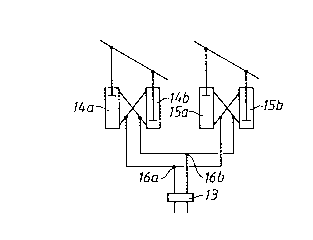
In Fig. 2 the two left-hand hydraulic cylinders 14a, 14b may
be regarded as being the cylinders located at a first bogie
of a railway vehicle for tilting the car body when the two
cylinders are working in opposite directions, while the two
right-hand hydraulic cylinders 15a, 15b may be reared as the
cylinders at a second bogie of the vehicle, also for
effecting tilting movements of the car body in the same way.
As can be concluded from the figure, the lower working
spaces of the left-hand cylinders 14a, 15a of the respective
first and second bogies are interconnected, while these
lower working spaces are also interconnected to the upper
working spaces of the right-hand cylinders 14b, 15b of the
respective first and second bogies, these interconnections
being symbolized by the conduits connected to point 16a of
Fig. 2. In a corresponding way, the lower working spaces of
the right-hand cylinders 14b, 15b of the respective first
and second bogies are interconnected, while these lower
working spaces are also interconnected to the upper working
spaces of the left-hand cylinders 14a, 15a of the respective
first and second bogies, these interconnections being
symbolized by the conduits connected to point 16b of Fig. 2.
The only existing servo valve 13 controls the tilt of the
car body through one connection to 16a and a second
connection to 16b, hence when operating the servo valve by
~064058
4a
pressing a fluid to one of the connections 16a or 16b
forcing all said hydraulic cylinders of the two bogies to
cooperate in order to tilt the body through a coordinated
rotational movement.
By the use of one single servo valve 13 (see Fig. 2), the
hydraulic cylinders 14a, 14b and 15a, 15b, respectively, of
the two bogies are controlled in parallel. As will be seen,
the hydraulic cylinders are also arranged to communicate
(see the hydraulic connections 16c, 16b. 14a and 15a are,
for example, interconnected and the pressure difference
between them will be rapidly equalized.
The angular difference that may arise between bogie 1 and
bogie 2 in a vehicle (see Fig. 3, ~ 2) is controlled
by the geometry of the superelevation.
The difference in tilting angle between different bogies
belonging to a car is adapted to be measured, the measured
signal thus indicating transition curves.
Both the time or space rate of change of the superelevation
and the lateral acceleration are adapted to be measured in
the vehicle. Upon multiplication of dacc/dt and dre/dtl a
correlation signal is obtained. A positive value indicates
a transition curve whereas low or negative values indicate a
straight track, a circular track or a track fault. It is
desirable to obtain a rapid indication of the lateral
acceleration, which deviates as little as possible from the
ideal. Normally, the signals to the different control
systems are filtered to eliminate disturbance, noise etc.
When a track fault occurs, a deviation from the ideal curve
takes place, and the degree of filtering can thereby be
- 2064058
_ 5
adjusted (upwards). This is an example of how to use a
correlation signal.
Figure 4a shows the acceleration signals, both the ideal and
the actual, when entering a transition curve. Figure 4b
shows the time rate of change daCC/dt. Figure 4c shows the
superelevation (re) and Figure 4d shows the time rate of
change thereof, dre/dt. It is also possible to measure its
space rate of change, for example by using the above-
mentioned angular difference ~. The ideal and actual
correlation signal is shown in figure 4e.
In a vehicle with tilting of the car body, the desired value
of the tilting is normally formed taking into account the
lateral acceleration according to the above. To avoid a
large tilting movement, this is normally limited to a
maximum value. Under winter conditions, snow which is
packed between the movable parts of the tilting system may
prevent the tilting movement, which, in turn, may lead to
unfavourable wheel unloads and uncomfortable ride. In the
case of such snow packing, great angular differences,
control errors and forces will arise in the servo system.
One or several of these quantities may be utilized for
indicating the presence of snow packing, for indicating the
degree of snow packing as well as for minimizing the risk of
wheel unload.
The angular difference is measured according to the above.
The control error is formed as the difference between the
actual value and the desired value whereas the forces may be
measured, for example, as the difference in hydraulic
pressure across the cylinders.
By indicating when the quantity exceeds an expected normal
threshold value and then measuring the current tilt angle, a
measure of the degree of snow packing is obtained. By
adapting the maximum limit of the desired value and hence
the tilt angle immediately after the indication, so that the
2064058
indication ceases, the risk of wheel unload is minimized
while at the same time obtaining an indication of the degree
of snow packing.
The means according to the above can be varied in many ways
within the scope of the following claims.