Note: Descriptions are shown in the official language in which they were submitted.
- 1 - 2~6~?37
S P E C I F I C A T I O N
OPTICAL CONNECTOR
TECHhiICAL FIELD
The present invention relates to an optical
connector for optically connecting tacketed optical
fibers.
BACKGROUND ART
As shown in Fig. 3, an optical fiber cord
includes a ~acketed optical fiber 1 formed of an
optical fiber la covered by a coating lb of nylon or
the like, a tension member 2 of aramid fiberæ or the
like arranged around the ~acketed optical fiber 1, and
a sheath 3 of polyvinyl chloride (PVC) covering these
elements. An optical connector for optically -
connecting optical fiber cords is attached to an end
portion of the ~acketed optical fiber 1.
This optical connector is assembled from a
plurality of components. As shown in Fig. 4, for
example, a rubber boot 4, ring 5, caulking ring 6,~
stop ring 7, and spring 8 are previously mounted, in
the order named,~ on the optical fiber cord to whicb
the optical connector is attached.
The sheath 3 at the distal end portion of the
optical fiber cord is removed, and a ferrule 9 is
attached to the distal end of the exposed Jacketed
optical fiber 1. Then, the components 4 to 8 are
successively pushed out toward the ferrule 9 in front,
as~indicated by the arrows, and are fixed to one
:~ :
?
:
.
,' .~ ; ~ : ' .:
37
-- 2
another, and thereafter, a plug frame 10 is fitted on
them, whereupon the optical connector is assembled.
Conventionally, these operations are performed
manually.
In performing this assembling operation, the
caulking ring 6 is staked so that the tension member 2
is caught and held between the caulking ring 6 and the
stop ring 7, and the distal end of the sheath 3 is
held between the ring 5 and the caulking ring 6, as
shown in Fig. 5, whereby the tensile strength of a
mounting portion of the optical fiber cord for the
optical connector is secured.
When the caulking ring 6 and the stop ring 7 are
pushed out forward, in assembling this optical
connector, the tension member 2 and the sheath 3 are
inevitably caught between the ~acketed optical fiber 1
and the stop ring 7 and between the ~acketed optical
fiber 1 and the caulking ring 6, respectively, as
shown in Fig. 6. In the assembling operation for the
optical connector, therefore, the tension member 2 and
the sheath 3 must be drawn out of the stop ring 7 and
the caulking ring 6, respectively, before staking the
caulking ring 6.
Having a wall thickness greater than that of the
tension member 2, however, the sheath 3 cannot be
easily drawn out of the caulking ring 6, so that the
removal work is very troublesome. Thus, the
assembling operation for the optical connector takes
trouble, so that the productivity is low, and
moreover, the assembling operation for the optical
connector cannot be mechanized.
The present invention has been contrived in
,
, ~ . ,
.:
- . - .
... - . .,. ~ ,. ~.. .: -.. - . : ~ :
- 3 - ~ ~ ~5~
consideration of these circumstances, and its object
is to provide a high-productivity optical connector
which attached to an end portion of an optical fiber
cord, and whose assembling operation is easy and can
be mechanized.
DISCLOSURE OF T~E INVENTION
In order to achieve the above object, according
to the present invention, there is provided an optical
connector which comprises a ferrule, provided on the
distal end of an optical fiber cord having a ~acketed
optical fiber covered by a sheath with a tension
member in between, and a stop ring whose distal end
position is regulated by the ferrule, in which a resin
boot for integrally fixing the respective distal ends
of the tension member and the sheath is provided on
the rear half of the stop ring by molding.
The resin boot, which integrally fixes the
respective distal ends of the tension member and the
sheath by the insert molding method, functions as a
rubber boot in a conventional optical connector.
BRIEF DESCRIPTION OF T~E DRAWINGS
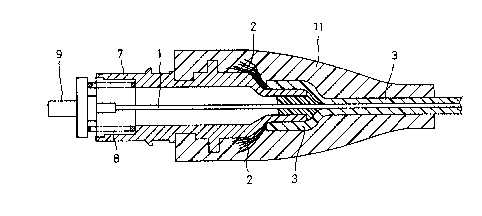
Figs. 1 and 2 show one embodiment of an optical
connector according to the present invention, in which
Fig. 1 is a sectional front view of the principal part
of the optical connector, and Fig. 2 is a perspective
view showing the way of molding a resin boot provided
on the respective distal ends of a tension member and
a sheath and integrally fixing them; and
Figs. 3 to 6 illustrate the construction of a
conventional optical connector, in which Fig. 3 is a
- .
2~ 3~
-- 4
front view showing the construction of an optical
fiber cord, Fig. 4 is an exploded view for
illustrating the assembly of the optical connector,
Fig. 5 is a sectional view of the principal part
showing the way a tension member is held by means of a
stop ring and a caulking ring, and Fig. 6 is a
sectional view o-f the principal part showing the
positional relationships between the stop ring,
caulking ring, and tension member.
BEST MODE OF CARRYING OUT T~E INVENTION
Referring now to Figs. 1 and 2, one embodiment of
the present invention will be described in detail. In
the description to follow, like reference numerals are
used to designate the same components as those of the
conventional optical connector described before.
In an optical connector of the present invention,
as shown in Fig. 1, a spring 8 is interposed between a
ferrule 9, which is attached to the distal end of a
jacketed optical fiber 1, and a stop ring 7 arranged
ad~acent to the ferrule 9, and a resin boot 11 is
provided on the rear half of the stop ring 7.
This resin boot 11, which is molded by the insert
molding method, serves to integrally fix the
respective distal ends of a tension member 2 and a
sheath 3, and to protect the rear half of the optical
connector.
A resin plug frame (not shown) is fitted on the
front half the stop ring 7, which has the resin boot
11 molded thereon.
The optical connector with this construction is
assembled in the following manner.
., - :
.
- 5 - 2~5~37
First, the stop ring 7 and the spring 8 are
previously mounted on an optical fiber cord.
Subsequently, the sheath 3 at the distal end
portion of the optical fiber cord is removed for a
predetermined length, and the ferrule 9 is attached to
the distal end of the exposed ~acketed optical fiber
1.
Thereafter, the stop ring 7, along with the
spring 8, is pushed out toward the ferrule 9 in front
so that the distal end of the stop ring 7 abuts
against the rear end of' the ferrule 9.
Then, the respective distal ends of the tension
member 2 and the sheath 3, caught between the Jacketed
optical fiber 1 and the stop ring 7 as the stop ring 7
is pushed out, are drawn out of the stop ring 7.
Subsequently, the ferrule 9, engaged with the
distal end of the stop ring 7, is mounted, along with
the jacketed optical fiber 1, on a lower mold 12 which
has a recess 12a, corresponding in shape to the resin
boot 11, and an in~ection groove 12b, as shown in Fig.
2.
Then, an upper mold 13, which has a recess (not
shown) and an in~ection groove 13b similar to those of
the lower mold 12, is placed on the lower mold 12 in
the manner indicated by dashed lines.
Thereafter, a resin is poured into both molds 12
and 13 through a passage defined by the in~ection
grooves 12b and 13b as a runner, whereupon the resin
boot 11 is molded on the rear half of the stop ring 7.
In this manner, the respective distal ends of the
tenslon member 2 and the sheath 3 of the optical fiber
cord are integrally fixed by means of the resin boot
-
.: . :........ ., : : . :
2~ ;.?~37
-- 6
11 .
Subsequently, the plug frame (not shown) is
fil,ted on the front half the stop ring 7, whereupon
assembling the optical connector is completed.
Thus, in the optical connector of the present
invention, the respective distal ends of the tension
member 2 and the sheath 3 are buried in the resin of
the molded resin boot 11 and fixed integrally with the
resin boot 11. Unlike the conventional optical
connector, therefore, the optical connector of the
invention does not require use of the ring 5 and the
caulking ring 6.
INDUSTRIAL APPLICABILITY
In the optical connector of the present
invention, as is evident from the above description,
the resin boot, which integrally fixes the respective
distal ends of the tension member and the sheath, is
provided on the rear half of the stop ring by molding,
so that the resin boot can be molded by only drawing
out the tension member and the sheath, caught between
the stop ring and the Jacketed optical fiber, from the
stop ring, and therefore, assembling the optical
connector is easy.
Further, the caulking ring or ring for holding
the tension member and the sheath need not be usedl so
that the components used can be reduced in number. As
compared with the case of the conventional optical
connector, therefore, the productivity is much
improved, and assembling the optical connector can be
mechanized and automated.
Since the tension member and the sheath are
.
' ' ' ~ ' . ' '
.
' ' ~-
.
.
.: . .
_ 7 _ 2 ~ 5 ~?37
buried in the resin boot, moreover, the optical
connector of the invention can enjoy various
industrial applications, taking advantage of, for
example, its tensile strength higher than that of the
conventional optical connector in which the tension
member and the sheath are fixed by caulking.
,
: - .
; ~ .
~; .''
:
... ., , ., . .. - - .- . . .. .:. . . .. : :
. ,, ., . . . . - -
, - , . - . . . .. ~ . . ~ ..
. : ~ .. . : . .