Language selection

Search

Patent 2065589 Summary

Third-party information liability

Some of the information on this Web page has been provided by external sources. The Government of Canada is not responsible for the accuracy, reliability or currency of the information supplied by external sources. Users wishing to rely upon this information should consult directly with the source of the information. Content provided by external sources is not subject to official languages, privacy and accessibility requirements.

Claims and Abstract availability

Any discrepancies in the text and image of the Claims and Abstract are due to differing posting times. Text of the Claims and Abstract are posted:

  • At the time the application is open to public inspection;
  • At the time of issue of the patent (grant).
(12) Patent: (11) CA 2065589
(54) English Title: FLUID FLOW CONTROLLER
(54) French Title: REGULATEUR DE DEBIT DE FLUIDE
Status: Expired and beyond the Period of Reversal
Bibliographic Data
(51) International Patent Classification (IPC):
  • F16K 31/126 (2006.01)
  • F16K 7/14 (2006.01)
(72) Inventors :
  • NISHIMURA, RYUTARO (Japan)
  • YAMAJI, MICHIO (Japan)
  • MAEDA, HIROKATSU (Japan)
  • IKEDA, NOBUKAZU (Japan)
  • YAMAMOTO, KENJI (Japan)
(73) Owners :
  • MASAKO KIYOHARA
(71) Applicants :
(74) Agent: RICHES, MCKENZIE & HERBERT LLP
(74) Associate agent:
(45) Issued: 1995-01-17
(22) Filed Date: 1992-04-08
(41) Open to Public Inspection: 1992-11-10
Examination requested: 1992-04-08
Availability of licence: N/A
Dedicated to the Public: N/A
(25) Language of filing: English

Patent Cooperation Treaty (PCT): No

(30) Application Priority Data:
Application No. Country/Territory Date
3-133450 (Japan) 1991-05-09

Abstracts

English Abstract


A fluid flow controller comprising a flow passage
which is opened and closed by the flexing of a
diaphragm secured at its periphery characterised in
that the diaphragm is a laminate of a plurality of
metal diaphragms and in that friction reducing
material is provided between the diaphragms.


Claims

Note: Claims are shown in the official language in which they were submitted.

The embodiments of the invention in which an exclusive
property or privilege is claimed are defined as follows:
1. A fluid flow controller comprising a flow passage
which is opened and closed by the flexing of a diaphragm
secured at its periphery characterized in that the diaphragm
is a laminate of a plurality of metal diaphragms and in that
friction reducing material is provided between the
diaphragms.
2. A fluid flow controller according to claim 1,
wherein the friction reducing material is lubricating oil
placed between the metal diaphragms.
3. A fluid flow controller of claim 1, wherein the
friction reducing material is a plating layer disposed on
the metal diaphragms.
4. A fluid flow controller according to claim 1
wherein the laminate member is clamped between the body of a
valve surrounding a fluid flow passage and the valve cover.
5. A fluid flow controller according to claim 2
wherein the laminate member is clamped between the body of a
valve surrounding a fluid flow passage and the valve cover.

11
6. A fluid flow controller according to claim 3
wherein the laminate member is clamped between the body of a
valve surrounding a fluid flow passage and the valve cover.
7. A fluid flow controller as claimed in any one of
claims 1 to 6 wherein a pressure fluid actuator operates to
relieve a spring biassed closure of the diaphragm.

Description

Note: Descriptions are shown in the official language in which they were submitted.


2065589
.
I
-1- I
" FLUID FLOW CONTROLL~R "
DESCRIPTION
The present invention relates to a fluid flow
controller used in fluid duct of, for example chemical
apparatus or mechanical apparatus, and in particular
to an improvement in the fluid flow controller which
uses the resilient flexing of a metal diaphragm to
open and close the flow passage.
A fluid flow controller of this type is hitherto known
as disclosed, for example, in the Japanese Laid-open
Patent Sho. 63-72984. This controller is basically
composed of a support member for the diaphragm, a
clamping member disposed so as to be capable of
bearing against the fixing member, and a laminate
consisting of a plurality of metal diaphragms with the
peripheral edges clamped between the support member
and clamping member.
The metal laminate is repeatedly deformed for the
purpose of fluid flow control.
~.

2065589
We have found that such a laminate had a short working
life and have appreciated that this is due to sliding
wear between the diaphragms in the laminate.
According to the present invention there is provided a
fluid flow controller comprising a flow passage which
is opened and closed by the flexing of a diaphragm
secured at its periphery characterised in that the
diaphragm is a laminate of a plurality of metal
diaphragms and in that friction reducing material is
provided between the diaphragms.
When the laminate is deformed, the adjacent diaphragms
slide on each other, but since a sliding and smoothing
anti-friction material is placed between them wear and
consequent damage is reduced.
The invention will now be described by way of example
and with reference to the drawings wherein:-
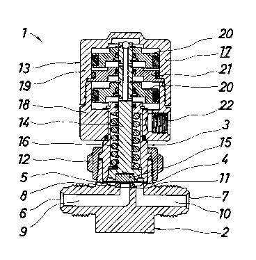
Figure 1 is a longitudinal sectional view showing a
fluid flow controller in a first embcdiment of the
invention;

- 2065589
Figure 2 is a magnified longitudinal sectional view of
essential parts of Figure 1.
A fluid flow controller 1 comprises a base body 2 with
an inlet 6 at the left side, an outlet 7 at the right
side, and a stepped concave chamber 8 opening upward.
The inlet 6 and the middle part of the bottom of the
concave chamber 8 communicate with each other through
a flow-in passage 9, and the right side of the bottom
of the concave chamber 8 and the outlet 7 through a
flow-out passage 10. An upwardly facing annular seat
11 is disposed at a part of the flow-in passage 9
opposite to the concave chamber 8, that is, in the
middle part of the bottom of the concave chamber 8.
A valve cover or bonnet 3 is arranged to be in clamping
relationship with body 2.
Thus the cover 3 is fitted into the enlarged part of
the concave chamber 8, and is fixed to the upper part
of the body 2 by a nut 12 screwed into the upper part
of the body 2.

` -
2065589
A plurality of metal diaphragms 4 are arranged as a
laminate with the peripheral edges held and fixed,
i.e. clamped between the member 2 and cover 3. In
this embodiment, being of direct type contacting
directly with the seat 11, three or four nickel alloy
discs of about 0.1 to 0.2 mm in thickness and about
25 to 30 mm~ in outside diameter are used.
The metal diaphragms 4 are put into the enlarged part
of the concave chamber 8, and their outer
circumferenci are clamped in airtight manner by the
cover 3. The laminates are operated, i.e. flexed by an
actuating mechanism 13.
The actuating mechanism 13 in this embodiment is of
reverse action pneumatic type and comprises a stem 14
elevatably disposed on the cover 3, a diaphragm
holder 15 being located in the lower part thereof to
abut against the metal diaphragms 4, a spring 16
urging the stem 14 downwardly being placed between the
cover 3 and stem 14, and a pneumatic actuator 17 for
lifting the stem 14 by pneumatic pressure such as air
pressure against the bias of spring 16 being mounted
on the upper part of the cover 3. The pneumatic

`- 2065S89
-- 5 --
actuator 17 is composed of an actuating body 18, an
actuator cap 19, a piston 20, a counterplate 21 and
a gas intake/exhaust port 22.
The sliding smoothing non-friction material 5 is
disposed between metal diaphragms 4 and is designed to
smooth their sliding, and in this embodiment it is a
lubricating oil 23 such as grease placed between metal
diaphragms 4, and it is applied to the contacting
surfaces of metal diaphraqms 4.
The operation is described below.
Figures 1 and 2 show the closed state, in which fluid
flow from the inlet 6 is arrested at the position of
the seat . In this state the elastic force of the
spring 16 presses stem 14 and the diaphragm holder 15
downward, and the middle part of the metal diaphragm
4 is deformed downwardly to be seated on.the seat
11.
When a pressure gas is supplied into the pneumatic
actuator 17, the stem 14 and diaphragm holder 15 are
moved upward against the elastic force of the spring

`- 2065589
16, and the metal diaphragms 4 are deformed upward by
their own elastic recovery and the fluid fram the
inlet 6 and are separated from the seat 11.
5 Therefore, the fluid fram the inlet 6 flaws in the route of flaw-in passage 9, concave chamber 8,
flow-out passage 10, and outlet 7, which is the open
state. When supply of pressure gas to the pneumatic
actuator 17 is stopped spring 16 closes the valve as
set out above.
Since the metal diaphragms 4 have their peripheral
edges held and fixed in airtight state between the
body 2 and cover 3, the fluid reaching the concave
chamber 8 will not leak outside.
For the purpose of fluid control, as the metal
diaphragms 4 are repeatedly deformed, the adjacent
ones will slide on each other, but since the
lubricating oil 23 is placed between them, they slide
smoothly.

206S589
Accordingly, wear, seizure or ~rly breakage due to
contact friction of the adjacent diaphragms 4 may be
avoided. As a result of experiment, the life could be
extended 1.5 to 2 times longer.
A second embadiment of the invention is described by
reference to Figure 3.
The second emkodiment is different from the first
embodiment in that the friction reducing sliding
smoothing material 5 is a plating layer 24 such as
silver plating disposed on each metal diaphragm 3.
In the second embodiment, the plating layer 24 is
applied on both face and reverse sides of each metal
diaphragm 3.
The fixing member 2 and tightening member 3 were body
and cover in the preceding embodiment, but these are
not limitative, and for example they may be actuator
body and actuator cap as disclosed in the Japanese
Laid-open Utility Model Sho. 61-119675.

2065589
The metal diaphragms 3 were of direct type directing
contacting with the seat in the foregoing embodiment,
but this is not limitative and for example they may be
of indirect type having a disc to be seated on the
seat as disclosed in the Japanese Laid-open Patent
Sho. 63-72984.
The sliding smoothing material 5 is not limited to the
lubricating oil 23 or plating layer 24 employed in the
above embodiments.
The actuating mechanism 13 was of pneumatic operating
type in the embodiments, but may be also of other
operating type or manual type.
The actuating mechanism 13 was of reverse action type
in the preceding embodiments, but it is not limitative
and it may be of, for example, normal action type.
As described herein, according to the invention, the
following excellent effects are brought about.

-- 2065589
(1) Being composed of flYing member, tightening
member, metal diaphragms and sliding smoothing
material, especially by using the sliding smoothing
material, the metal diaphragms are not broken early if
deformed repeatedly, and the life may be notably
extended.
(2) Only by providing with the sliding smoothing
material, the cost is not increased so much, and it
may be easily applied to the existing structure.
(3) By using lubricating oil or plating layer as the
sliding smoothing material, it also contributes to
prevention of rusting of the metal diaphragms.

Representative Drawing
A single figure which represents the drawing illustrating the invention.
Administrative Status

2024-08-01:As part of the Next Generation Patents (NGP) transition, the Canadian Patents Database (CPD) now contains a more detailed Event History, which replicates the Event Log of our new back-office solution.

Please note that "Inactive:" events refers to events no longer in use in our new back-office solution.

For a clearer understanding of the status of the application/patent presented on this page, the site Disclaimer , as well as the definitions for Patent , Event History , Maintenance Fee  and Payment History  should be consulted.

Event History

Description Date
Time Limit for Reversal Expired 2010-04-08
Letter Sent 2009-04-08
Inactive: Office letter 2006-05-23
Inactive: Corrective payment - s.78.6 Act 2006-04-18
Inactive: IPC from MCD 2006-03-11
Inactive: Entity size changed 2003-08-20
Inactive: Late MF processed 2003-07-10
Grant by Issuance 1995-01-17
Application Published (Open to Public Inspection) 1992-11-10
All Requirements for Examination Determined Compliant 1992-04-08
Request for Examination Requirements Determined Compliant 1992-04-08

Abandonment History

There is no abandonment history.

Maintenance Fee

The last payment was received on 

Note : If the full payment has not been received on or before the date indicated, a further fee may be required which may be one of the following

  • the reinstatement fee;
  • the late payment fee; or
  • additional fee to reverse deemed expiry.

Please refer to the CIPO Patent Fees web page to see all current fee amounts.

Fee History

Fee Type Anniversary Year Due Date Paid Date
MF (patent, 6th anniv.) - small 1998-04-08 1998-02-12
MF (patent, 7th anniv.) - small 1999-04-08 1999-01-22
MF (patent, 8th anniv.) - small 2000-04-10 2000-02-04
MF (patent, 9th anniv.) - small 2001-04-09 2001-01-29
MF (patent, 10th anniv.) - small 2002-04-08 2002-01-31
Reversal of deemed expiry 2003-04-08 2003-01-23
MF (patent, 11th anniv.) - standard 2003-04-08 2003-01-23
MF (patent, 12th anniv.) - standard 2004-04-08 2003-11-26
MF (patent, 13th anniv.) - standard 2005-04-08 2005-02-07
MF (patent, 14th anniv.) - standard 2006-04-10 2006-03-31
2006-04-18
MF (patent, 15th anniv.) - standard 2007-04-10 2007-03-29
MF (patent, 16th anniv.) - standard 2008-04-08 2008-02-25
MF (application, 2nd anniv.) - small 02 1994-04-08
Owners on Record

Note: Records showing the ownership history in alphabetical order.

Current Owners on Record
MASAKO KIYOHARA
Past Owners on Record
HIROKATSU MAEDA
KENJI YAMAMOTO
MICHIO YAMAJI
NOBUKAZU IKEDA
RYUTARO NISHIMURA
Past Owners that do not appear in the "Owners on Record" listing will appear in other documentation within the application.
Documents

To view selected files, please enter reCAPTCHA code :


To view images, click a link in the Document Description column. To download the documents, select one or more checkboxes in the first column and then click the "Download Selected in PDF format (Zip Archive)" or the "Download Selected as Single PDF" button.

List of published and non-published patent-specific documents on the CPD .

If you have any difficulty accessing content, you can call the Client Service Centre at 1-866-997-1936 or send them an e-mail at CIPO Client Service Centre.


Document
Description 
Date
(yyyy-mm-dd) 
Number of pages   Size of Image (KB) 
Abstract 1995-01-17 1 11
Cover Page 1995-01-17 1 20
Description 1995-01-17 9 210
Claims 1995-01-17 2 38
Drawings 1995-01-17 1 55
Representative drawing 1999-07-07 1 23
Late Payment Acknowledgement 2003-08-20 1 167
Maintenance Fee Notice 2009-05-20 1 171
Fees 2003-01-23 1 38
Fees 2003-07-10 1 43
Fees 2002-01-31 1 38
Fees 2003-11-26 1 36
Fees 2000-02-04 1 39
Fees 1999-01-22 1 44
Fees 2001-01-29 1 40
Fees 1998-02-12 1 44
Fees 2005-02-07 1 33
Fees 2006-03-31 1 35
Correspondence 2006-05-23 1 15
Fees 2007-03-29 1 44
Fees 2008-02-25 1 49
Fees 1997-01-29 1 40
Fees 1996-01-26 1 41
Fees 1995-02-03 1 46
Fees 1994-01-05 1 32
PCT Correspondence 1994-10-19 1 65
Courtesy - Office Letter 1992-11-25 1 50
Prosecution correspondence 1994-03-08 2 61