Language selection

Search

Patent 2065655 Summary

Third-party information liability

Some of the information on this Web page has been provided by external sources. The Government of Canada is not responsible for the accuracy, reliability or currency of the information supplied by external sources. Users wishing to rely upon this information should consult directly with the source of the information. Content provided by external sources is not subject to official languages, privacy and accessibility requirements.

Claims and Abstract availability

Any discrepancies in the text and image of the Claims and Abstract are due to differing posting times. Text of the Claims and Abstract are posted:

  • At the time the application is open to public inspection;
  • At the time of issue of the patent (grant).
(12) Patent: (11) CA 2065655
(54) English Title: PLURAL TIME CONSTANT SIGNAL CONTROL
(54) French Title: COMMANDE DE SIGNAUX A CONSTANTES DE TEMPS MULTIPLES
Status: Expired and beyond the Period of Reversal
Bibliographic Data
(51) International Patent Classification (IPC):
  • H03G 3/20 (2006.01)
  • H03G 3/34 (2006.01)
(72) Inventors :
  • LENDARO, JEFFERY BASIL (United States of America)
(73) Owners :
  • THOMSON CONSUMER ELECTRONICS, INC.
(71) Applicants :
  • THOMSON CONSUMER ELECTRONICS, INC. (United States of America)
(74) Agent: CRAIG WILSON AND COMPANY
(74) Associate agent:
(45) Issued: 1996-07-30
(22) Filed Date: 1992-04-09
(41) Open to Public Inspection: 1992-11-07
Examination requested: 1992-04-09
Availability of licence: N/A
Dedicated to the Public: N/A
(25) Language of filing: English

Patent Cooperation Treaty (PCT): No

(30) Application Priority Data:
Application No. Country/Territory Date
696,490 (United States of America) 1991-05-06

Abstracts

English Abstract


The present invention concerns apparatus having a
voltage controlled amplifier wherein the gain of the amplifier is
determined in response to the level of a control signal at an input
terminal. A first rate of change is used for a change of gain from a
low signal level to a higher signal level, and a second rate of
change is used for a change from a high signal level to a lower
signal level with the second rate being faster than the first rate.


Claims

Note: Claims are shown in the official language in which they were submitted.

-4-
Claims:
1. Apparatus for controlling signal level comprising:
a voltage controlled amplifier wherein the gain of the
amplifier is determined in response to the level of a control signal
at an input terminal,
control means for generating said control signal,
first time constant means coupled to said control
means for causing said control signal to change from a low level of
gain to a higher level at a first rate of change, and
second time constant means coupled to said control
means for causing said control signal to change from the higher
level of gain to a lower level at a second rate of change,
the second rate of change being faster than the first
rate of change.
2. The apparatus of claim 1 wherein the first time
constant means comprises a first resistor and a capacitor and the
second time constant means comprises the capacitor and a diode
shunting the first resistor.
3. The apparatus of claim 2 wherein the second time
constant further comprises a resistor in series with the diode, said
second resistor having a resistance value less than the first
resistor.
4. Apparatus for controlling audio volume comprising:
a voltage controlled amplifier for amplifying an audio
signal wherein the gain of the amplifier is determined in response
to the level of a control signal at an input terminal,
control means for generating said control signal,
first time constant means coupled to said control
means for causing said control signal to change from a low level of
volume to a higher level at a first rate of change, and
second time constant means coupled to said control
means for causing said control signal to change from the higher
level of volume to a lower level at a second rate of change,
the second rate of change being faster than the first
rate of change.

-5-
5. Apparatus for muting audio volume comprising:
a voltage controlled amplifier for amplifying an audio
signal wherein the gain of the amplifier is determined in response
to the level of a control signal at an input terminal,
control means for generating said control signal,
first time constant means coupled to said control
means for causing said control signal to change from a low level of
volume to a higher level at a first rate of change, and
second time constant means coupled to said control
means for causing said control signal to change from the higher
level of volume to a lower level at a second rate of change,
the second rate of change being faster than the first
rate of change for muting the volume of the audio signal in
response to a change of operational status of the apparatus.

Description

Note: Descriptions are shown in the official language in which they were submitted.


-1- 20~56~
.
PLURAL TIME CONSTANT SIGNAL CONTROL
BACKGROI~ND
The present invention relates to television receivers, and more
5 particularly, to the processing of signals receiver by television or FM
receiver, with particular application to audio signals.
For a more pleasing sound from a television receiver, it may be
desirable to cause the level of a signal to increase slowly but still to have a
quick decrease in level under some circumstances. This type of different
10 rate signal change can be desirable during a power-up operation, following
a channel change, or following a customer un-mute from a remote control
so that a slow rise time takes the edge off the signal "attack". This is
especially desirable when there is a channel change with the new channel
having a loud audio level. However, on a user mute when going into a
15 channel change and just before set turn-off, the user expects a quick
reduction of audio level and may be disturbed if the lowering of the signal
level takes too long. Accordingly, it is recognized herein that a signal
control having a slow rate of change for increasing signals and a faster rate
of change for decreasing signals is desirable for achieving these results.
2 0 As used herein the term "signal" can be an audio signal, video
composite signal, luminance signal, chroma signal, etc. even though the
exemplary embodiment particularly discusses an audio signal.
SUMMARY OF THE INVENTION
2 5 The present invention concerns apparatus having a voltage
controlled amplifier wherein the gain of the amplifier is determined in
response to the level of a control signal at an input terminal. A first rate of
change is used for a change of gain from a low signal level to a higher
signal level, and a second rate of change is used for a change from a high
3 0 signal level to a lower signal level with the second rate being faster than
the first rate.
BREF DESCRIPrION OF T~E DRAWINGS
Figure 1 shows part block diagram and part schematic
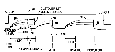
3 5 representation of the circuit according to aspects of the present invention.Figure 2 shows a graphic representation of a representative
timing curves applicable when using aspects of the present invention
shown in Figure 1.
.~

-2- 206~655
DETALED DESCRIP~ION OF THE PREFERRED EMBODIMENT
Referring now to Figure 1, there is shown a digital to analog
converter (DAC) 10 providing an analog audio level control signal at
terminal 12. In the exemplary embodiment, the audio control signal is
5 derived from the microprocessor control IC in response to signals received
from a remote control. The audio signal can be derived from a television
source, FM source, CD disk player, or the like (not shown). If derived from
a television source such as a broadcast station, satellite source, or cable
television source, the audio signal is part of a composite signal which is
1 0 detected in the usual way for providing a sound IF signal which is then
detected to provide the audio signal. The derived audio signal is coupled
to a gain controlled amplifier 14 for processing of the derived audio signal
with the gain controlled by the control signal at the output pin 12 of DAC
10. Thus, the output signal at pin 12 is not the audio signal itself but the
15 control signal for determining the level of the audio signal which, is
subsequently coupled to power amplifiers and loudspeakers (not shown).
As explained above, it is desirable from a user satisfaction
point of view, that the rates of change for the audio sound be different
when changing from a lower level to a higher level of sound than when
2 0 changing from a higher level of sound to a lower level. The gain of gain
controlled amplifier 14 is adjustable in response to a control signal applied
to pin 16. The volume level control signal at pin 12 is coupled to capacitor
18 through resistor 20 for establishing a first time constant with the
voltage across capacitor 18 and at terminal 16 increasing at a first rate.
2 5 For lowering the volume level, the discharge of capacitor 18 and the
change of voltage at pin 16 is accomplished by discharge of capacitor l 8
through diode 22 through the impedance present at terminal 12, which
could be the output impedance of DAC 10 at terminal 12 and/or an
external resistor coupled between terminal 12 and ground (not shown).
3 0 Thus, upon a decrease in sound level, the voltage across capacitor 18 and
at terminal 16 is changed at a second rate which is faster than the first
rate. If the second rate is deemed to be too fast, it can be adjusted by
coupling a resistor 24 in series with diode 22 for slowing the second rate
while still keeping the second rate faster than the first rate of change.
3 5 As applied to an audio system, reference can be had to the
timing and level diagrams of Figure 2 where it is shown that it is desirable
to have a rapid decrease in sound level when certain operational changes
are accomplished in the signal receiver. For example upon set power-on
shown by diagram 26, the sound level is increased, as shown by curve 28,
4 0 to one of various levels which were previously set by the user. Upon

-3- 20656~5
initiation of a change of channel, it may be desirable that the sound be
rapidly decreased as shown by curve 30 thus effectively muting the sound
during the change of channel. Once the channel has been selected, the
sound will again be increased to a level as shown by curve 32. If a mute is
5 initiated from a remote control or the like, the sound is rapidly lowered as
shown by curve 34 and kept at that "off" level until the sound is un-muted
wherein the sound increases in level as shown in curve 36 to the previous
level. Upon the set being shut-off as shown by diagram 26, the sound is
rapidly lowered as shown by curve 38 so that disruptions of operational
1 0 status within the set during power-down do not cause audio transients
which would be audible to the user.

Representative Drawing
A single figure which represents the drawing illustrating the invention.
Administrative Status

2024-08-01:As part of the Next Generation Patents (NGP) transition, the Canadian Patents Database (CPD) now contains a more detailed Event History, which replicates the Event Log of our new back-office solution.

Please note that "Inactive:" events refers to events no longer in use in our new back-office solution.

For a clearer understanding of the status of the application/patent presented on this page, the site Disclaimer , as well as the definitions for Patent , Event History , Maintenance Fee  and Payment History  should be consulted.

Event History

Description Date
Inactive: IPC from MCD 2006-03-11
Time Limit for Reversal Expired 2002-04-09
Letter Sent 2001-04-09
Grant by Issuance 1996-07-30
Application Published (Open to Public Inspection) 1992-11-07
All Requirements for Examination Determined Compliant 1992-04-09
Request for Examination Requirements Determined Compliant 1992-04-09

Abandonment History

There is no abandonment history.

Fee History

Fee Type Anniversary Year Due Date Paid Date
MF (patent, 6th anniv.) - standard 1998-04-09 1998-03-03
MF (patent, 7th anniv.) - standard 1999-04-09 1999-03-01
MF (patent, 8th anniv.) - standard 2000-04-10 1999-12-22
Owners on Record

Note: Records showing the ownership history in alphabetical order.

Current Owners on Record
THOMSON CONSUMER ELECTRONICS, INC.
Past Owners on Record
JEFFERY BASIL LENDARO
Past Owners that do not appear in the "Owners on Record" listing will appear in other documentation within the application.
Documents

To view selected files, please enter reCAPTCHA code :


To view images, click a link in the Document Description column. To download the documents, select one or more checkboxes in the first column and then click the "Download Selected in PDF format (Zip Archive)" or the "Download Selected as Single PDF" button.

List of published and non-published patent-specific documents on the CPD .

If you have any difficulty accessing content, you can call the Client Service Centre at 1-866-997-1936 or send them an e-mail at CIPO Client Service Centre.


Document
Description 
Date
(yyyy-mm-dd) 
Number of pages   Size of Image (KB) 
Cover Page 1994-03-19 1 20
Abstract 1994-03-19 1 17
Claims 1994-03-19 2 68
Drawings 1994-03-19 1 26
Description 1994-03-19 3 140
Abstract 1996-07-30 1 14
Cover Page 1996-07-30 1 14
Description 1996-07-30 3 147
Claims 1996-07-30 2 67
Drawings 1996-07-30 1 17
Representative drawing 1999-07-09 1 8
Maintenance Fee Notice 2001-05-07 1 178
Fees 1996-03-21 1 50
Fees 1997-03-07 1 63
Fees 1995-03-23 1 72
Fees 1994-03-17 1 63
Courtesy - Office Letter 1992-11-26 1 48
PCT Correspondence 1996-05-17 1 49