Language selection

Search

Patent 2065696 Summary

Third-party information liability

Some of the information on this Web page has been provided by external sources. The Government of Canada is not responsible for the accuracy, reliability or currency of the information supplied by external sources. Users wishing to rely upon this information should consult directly with the source of the information. Content provided by external sources is not subject to official languages, privacy and accessibility requirements.

Claims and Abstract availability

Any discrepancies in the text and image of the Claims and Abstract are due to differing posting times. Text of the Claims and Abstract are posted:

  • At the time the application is open to public inspection;
  • At the time of issue of the patent (grant).
(12) Patent: (11) CA 2065696
(54) English Title: METHOD FOR CONNECTING OPTICAL FIBERS
(54) French Title: METHODE DE CONNEXION DE FIBRES OPTIQUES
Status: Expired and beyond the Period of Reversal
Bibliographic Data
(51) International Patent Classification (IPC):
  • G02B 06/255 (2006.01)
(72) Inventors :
  • OSAKA, KEIJI (Japan)
  • YANAGI, TORU (Japan)
(73) Owners :
  • SUMITOMO ELECTRIC INDUSTRIES, LTD.
(71) Applicants :
  • SUMITOMO ELECTRIC INDUSTRIES, LTD. (Japan)
(74) Agent: KIRBY EADES GALE BAKER
(74) Associate agent:
(45) Issued: 1997-01-07
(22) Filed Date: 1992-04-09
(41) Open to Public Inspection: 1992-10-13
Examination requested: 1993-03-24
Availability of licence: N/A
Dedicated to the Public: N/A
(25) Language of filing: English

Patent Cooperation Treaty (PCT): No

(30) Application Priority Data:
Application No. Country/Territory Date
171584/1991 (Japan) 1991-04-12

Abstracts

English Abstract


The present invention is directed to a method of
connecting hermetic optical fibers having a hermetic layer
coated on optical fiber glass. The method comprises
positioning the optical fibers on respective electrically non-
conductive V-shaped grooves, aligning the optical fibers and
fusing and connecting the optical fibers through aerial
discharge. The method of the present invention provides
hermetic optical fibers having a small decrease in break
strength after the connection is made without needing to
remove the hermetic layer.


Claims

Note: Claims are shown in the official language in which they were submitted.

-5-
Claims:
1. A method for connecting hermetic optical fibers
having a hermetic layer coated on an optical fiber glass,
which comprises positioning the optical fibers on respective
electrically nonconductive V-shaped grooves, aligning the
optical fibers and fusing and connecting the optical fibers
through aerial discharge.
2. The method according to claim 1, wherein a material
forming the electrically nonconductive V-shaped groove has a
resistivity of larger than 10+8 ohmm.
3. The method according to claim 1, wherein the aerial
discharge is conducted so that the fusion temperature is from
1600 to 2000°C.

Description

Note: Descriptions are shown in the official language in which they were submitted.


-1- 2065696
Method for Connection Optical Fibers
The present invention relates to a method for fusing and
connecting so-called hermetic optical fibers which have a thin
film coating layer of, for example, a metal or carbon on a
surface of an optical fiber glass.
In the description that follows reference is made to
Figure 3. For the sake of convenience all of the figures will
be introduced briefly as follows:
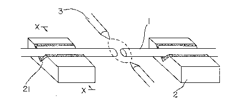
Fig. lA is a perspective view of an embodiment of a
method according to the present invention.
Fig. lB is a cross-sectional view along the X-X line of
Fig. lA.
Fig. 2 shows a splice loss characteristic histogram of
hermetic optical fibers connected according to the method of
the present invention.
Fig. 3 shows the break strength of carbon coated hermetic
optical fibers after splicing with and without removing the
carbon layer according to conventional methods.
Fig. 4 shows a grounding test procedure conducted as a
Comparative Example.
Hitherto, a method for fusing and connecting optical
fibers involved use of aerial discharge heat to permanently
connect the optical fibers. Such a method is advantageous in
that (l) connection loss is small, (2) excellent reliability
over the long term is obtained because the connected part is
reinforced with a heat-shrink tube and the like after the
connection is made.
A hermetic optical fiber has (l) improved water
resistance and (2) improved reliability over the long term by
coating a thin film of a metal, carbon or the like on an
optical fiber surface. Since the surface of the hermetic
optical fiber is electrically conductive, the strength after
the connection is decreased. The reason therefor has been
thought to be that the hermetic layer material is incorporated
in the fused and connected part of the optical fiber.

~ -2- 2065696
In order to solve this problem, a method has been
proposed for connecting carbon hermetic optical fibers, which
comprises removing a carbon layer immediately before setting
the fibers on a fusing instrument, and fusing and connecting
the hermetic optical fibers through aerial discharge (Japanese
Patent Kokai Publication No. 195304/1990 (Japanese Patent
Application No. 14638/1989)).
A sample connected by this method and a sample fused and
connected without removal of the hermetic layer were subjected
to a break strength test. The results of the break strength
are shown in the Table below and Fig. 3. The sample prepared
by removing the carbon layer and fusing and connecting the
optical fibers has an average break strength of almost twice
that of the sample without removal of the carbon layer.
Characteristically, the breakage always occurred on a V-shaped
groove made of a metal.
TABLE
No. Steps Number of Average Maximum Minimum Number of
samples value value value breaks at
V ~oove
coverage removal - 20 0.7 1.1 0.5 16
cutting - fusion
2 coverage removal - 20 1.4 1.8 0.8 8
cutting -
carbon removal -
fusion
As stated above, the method for fusing and connecting the
optical fibers after removing the carbon layer gives a
connection having a slight decrease in strength. But, removal
of the carbon layer is effected through thermal decomposition
by heating the carbon layer to higher than 500C, preferably
500 to 1,000C, thereby requiring much labour and time.
An object of the present invention is to provide a method
for connecting hermetic optical fibers without removing a
hermetic layer, which method forms a high strength connection
between the hermetic optical fibers.

- -3- 2065696
This and other objects of the present invention are
achieved by a method for connecting hermetic optical fibers
having a hermetic layer coated on an optical fiber glass,
which comprises positioning the optical fibers on respective
electrically nonconductive V-shaped grooves, aligning the
optical fibers and fusing and connecting the optical fibers
through aerial discharge.
Fig. 1 shows an embodiment of the method according to the
present invention. Fig. lA is a perspective view as a whole
and Fig. lB is a cross-sectional view along the X-X line. A
hermetic optical fiber 1 has a hermetic layer made of, for
example, a metal and carbon, coated on the optical fiber glass
surface. A pedestal 2 has a V-shaped groove 21 in a part made
of an electrically nonconductive material which contacts with
the optical fiber 1. The pedestal 2 may be made of an
electrically nonconductive material as a whole. A pair of
discharge electrodes 3 fuses the hermetic optical fibers by
aerial discharge heat.
As shown in the figure, the hermetic optical fibers are
located on the electrically nonconductive V-shaped groove 21
of the pedestal 2 without removing the hermetic layer, the
cores are aligned and then the optical fibers are fused and
connected.
A nonconductive material forming the V-shaped groove has
a resistivity of larger than 10~8 ohm-m and specific examples
include ceramics, glass, zirconia and alumina. The diameter
of the hermetic optical fiber is usually from 5 to 1000,
preferably from 50 to 300, more preferably from 120 to 130 ~m.
Thickness of the hermetic layer is usually from 100 to 1000 A.
The aerial discharge is conducted so that the fusion
temperature is usually from 1000 to 2500C, preferably from
1600 to 2000C. Specific examples of the material
hermetically coated on the fiber are nickel, copper, aluminum,
gold, carbon, boron, titanium and magnesium.
The present invention will be illustrated by the
following Example. The invention should not be construed to
be limited to this preferred embodiment.

~4~ 2065696
Example
As shown in Fig. 1, hermetic optical fibers each of which
had a carbon layer of about 500 A in thickness coated on an
outer surface of a single mode optical fiber having a diameter
of 125 ~m were positioned on the electrically nonconductive V-
shaped groove. Cores of the fibers were aligned and then the
optical fibers were fused and connected. Average break
strength was 1.4 kg. Connection loss was as shown in Fig. 2
and average loss was 0.04 dB.
A comparison test was conducted. The hermetic optical
fibers were positioned on the electrically nonconductive V-
shaped groove. While contacting a grounded copper wire 4 with
the hermetic optical fiber at the point between the electrode
3 and the pedestal 2, the discharge was conducted to fuse and
connect the optical fibers. Average break strength of the
connected part decreased to 0.6 kg.
According to the present invention, a connection having a
small decrease in break strength after the connection is made
can be obtained without passing a current in the optical fiber
surface during the fusion and connection.

Representative Drawing
A single figure which represents the drawing illustrating the invention.
Administrative Status

2024-08-01:As part of the Next Generation Patents (NGP) transition, the Canadian Patents Database (CPD) now contains a more detailed Event History, which replicates the Event Log of our new back-office solution.

Please note that "Inactive:" events refers to events no longer in use in our new back-office solution.

For a clearer understanding of the status of the application/patent presented on this page, the site Disclaimer , as well as the definitions for Patent , Event History , Maintenance Fee  and Payment History  should be consulted.

Event History

Description Date
Time Limit for Reversal Expired 2003-04-09
Letter Sent 2002-04-09
Grant by Issuance 1997-01-07
All Requirements for Examination Determined Compliant 1993-03-24
Request for Examination Requirements Determined Compliant 1993-03-24
Application Published (Open to Public Inspection) 1992-10-13

Abandonment History

There is no abandonment history.

Fee History

Fee Type Anniversary Year Due Date Paid Date
MF (patent, 6th anniv.) - standard 1998-04-09 1998-03-20
MF (patent, 7th anniv.) - standard 1999-04-09 1999-03-17
MF (patent, 8th anniv.) - standard 2000-04-10 2000-03-16
MF (patent, 9th anniv.) - standard 2001-04-09 2001-03-16
Owners on Record

Note: Records showing the ownership history in alphabetical order.

Current Owners on Record
SUMITOMO ELECTRIC INDUSTRIES, LTD.
Past Owners on Record
KEIJI OSAKA
TORU YANAGI
Past Owners that do not appear in the "Owners on Record" listing will appear in other documentation within the application.
Documents

To view selected files, please enter reCAPTCHA code :


To view images, click a link in the Document Description column. To download the documents, select one or more checkboxes in the first column and then click the "Download Selected in PDF format (Zip Archive)" or the "Download Selected as Single PDF" button.

List of published and non-published patent-specific documents on the CPD .

If you have any difficulty accessing content, you can call the Client Service Centre at 1-866-997-1936 or send them an e-mail at CIPO Client Service Centre.


Document
Description 
Date
(yyyy-mm-dd) 
Number of pages   Size of Image (KB) 
Description 1997-01-06 4 177
Abstract 1997-01-06 1 17
Claims 1997-01-06 1 18
Drawings 1997-01-06 2 27
Abstract 1994-03-29 1 13
Claims 1994-03-29 1 14
Drawings 1994-03-29 2 23
Description 1994-03-29 4 150
Representative drawing 1999-07-25 1 5
Maintenance Fee Notice 2002-05-06 1 179
Fees 1997-03-05 1 104
Fees 1996-02-28 1 78
Fees 1994-02-22 1 43
Fees 1995-03-22 1 83
Courtesy - Office Letter 1993-04-13 1 70
PCT Correspondence 1996-10-27 1 45
Prosecution correspondence 1993-03-23 9 308