Note: Descriptions are shown in the official language in which they were submitted.
~ 2065850
BACKGROUND OF THE INVENTION
There are a varlety of known ways to prlnt hard copy
in black and white and ln color . Tradlt ional technlques
lnclude letterpress prlntlng, rotogravure printing and offset
print ing . These convent ional prlnt ing procesEes produce hlgh
sluallty coples. However, when only a limlted number of coples
are reS~ulred, the coples are relatively expenslve. In the
case of letterpress and gravure prlntlng, the ma~or expense
results from the fact that the lmage must be cut or etched
into the plate using expenslve photographlc masklng and
chemical etching technl~ues. PlQtes are also re~ulred ln
offset llthography. However, the plates are in the form of
mats or films that are relatively ineXpensive to make. The
image is present on the plate or mat as hydrophil~c (water-
receptive) and hydrophobic ~water-repellent) surface areas7
hydrophobic areas are generally oleophilic, or ink-receptive,
as well. In wet llthography, water and then lnk are applied
to the surface of the plate. Water tends to adhere to the
hydrophilic or water-receptlve areas of the plate, creatlng a
thln f ilm of water thereon which does not accept ink . The ink
does adhere to the hydrophobic areas of the plate and those
inked areas, usually
64421 -494
~ W092/01567 2 0 6 5 8 5 0 PCI/US91/04206
--2--
uULL~ on~lin~ to the printed areas of the original document,
are transferred to a relatively soft blanket cylinder and, from
there, to the paper or other recording medium brought into
contact with the surface of the blanket cylinder by an
impression cylinder.
Most conventional offset plates are also produced
photographically. In a typical negative-working, subtractive
process, the original document is photographed to produce a
photographic negative. The negative is placed on an aluminum
plate having a water-receptive oxide surface that is coated
with a photopolymer. Upon being exposed to light through the
negative, the areas of the coating that received light
(._ulLe~ol~ding to the dark or printed areas of the original)
cure to a durable oleophilic state. The plate is then subjected
to a developing process which removes the noncured areas of the
coating that did not receive light (corresponding to the light
or baukyLuu..d areas of the original). The resultant plate now
carries a positive or direct image of the original document.
If a press is to print in more than one color, a separate
printing plate corresponding to each color is required, each of
which is usually Dade photographically as af oresaid . In
addition to preparing the appropriate plates f or the dif f erent
colors, the plates must be mounted properly on the plate
cylinders in the press and the angular positions of the
cylinders coordinated so that the color components printed by
the different cylinders will be in register on the printed
copies .
The development of lasers has simplif ied the production of
lithographic plates to some extent. Instead of applying the
original image photographically to the photoresist-coated
printing plate as above, an original document or picture is
scanned line-by-line by an optical scanner which develops
strings of picture signals, one for each color. These signals
are then used to control a laser plotter that writes on and
.hus exposes the photoresist coating on the lithographic plate
~ 2065850
~to cure the coat lng ln those areas whlch recelve llght . That
plate iB then developed in the usual way by removing the
unexposed areas of the coatlng to create a direct lma~e on the
plate for that color. Thus, lt ls stlll necessary to
chemlcally etch each plate ln order to create an lmage on that
plate .
There have been some attempts to use more powerful
lasers to wrlte lmages on llthographlc plates by volatlllzlng
the surface coatlng 90 as to avold the need for subsequent
developlng. However, the use of such la6ers for thls purpose
has not been entlrely satlsfsctory because the coatlng on the
plate must be compatlble wlth the partlcular laser; thls
requlrement llmlts the cholce of coatlng materials. Also, the
pulslng frequencies of some lasers used for thls purpose are
80 low that the time required to produce a halftone lmage on
the plate 18 unacceptably long.
There have also been some attempts to use scannlng
~-beam apparatus to etch away the surface coatlngs on plates
used for prlntlng. However, such machlnes are very expenslve.
~0 In addltion, they requlre that the workplece, l.e. the plate,
be malntalne~l ln a complete vacuum, maklng such apparatus
impractlcal for day-to-day use ln a prlntlng faclllty.
Images have also been applled to a llthograph~c
plste by electroeroslon. A type of plate sultable for lmaglng
ln thls fashlon, and dlsclosed ln U.S. Patent 4,596,733, has
sn oleophlllc plsstlc substrate. e.g. Mylar brand plsstlc
fllm, havlng a thln coatlng of aluMlnum metal wlth an
*trade-mark
B 64421-494
... .. .. .... .. .. .... . . . _ _ . _ _ _ . _ .
~ 2065850
3a
overcoatlng that contalns conductlve graphlte; the coatlng
acts as a lubrlcant and protects tlle alumlnum layer agalnst
scratching. A stylus electrode ln contact with the graphlte-
contalnlng surface coat lng 18 caused to move across tlle
surface of the plate and is pulsed ln accordance wlth incom~ng
plcture slgnals. The resultant current flow between the
electrode and the th~n metal coatlng is by deslgn large enough
to erode away the thln metal coatlng and the overlylng
c onduct ~ ve graph 1 t e
.~ . .
B 64221-494
WO92/01567 PCI/US91/042
.
-4~ 2065850
containing surface coating, thereby exposing the underlying ink
receptive plastic substrate on the areas of the plate
corresponding to the printed portions of the original document.
This method of making lithographic plates is disadvantaged in
that the described electroerosion process only works on plates
whose conductive 6urf ace coatings are very thin; moreover, the
stylus electrode which contacts the 6urface of the plate
60metimes scratches the plate. This degrades the image being
written onto the plate because the scratches constitute
inadvertent or unwanted image areas on the plate which print
unwanted marks on the copies.
Finally, we are aware of a press system which images a
lithographic plate while the plate is actually mou~ted on the
plate cylinder in the press. The cylindrical surface of the
plate, treated to render it either oleophilic or hydrophilic,
is written on by an ink jetter arranged to scan over the
surface of the plate. The ink jetter is controlled so as to
deposit on the plate surface a thermoplastic image-forming
resin or material which has a desired affinity for the printing
ink being used to print the copies. For example, the image-
forming material may be attractive to the printing ink so that
the ink adheres to the plate in the areas thereof where the
image-forming material is present, and resistant to the "wash"
used in the press to prevent inking of the background areas of
the image on the plate.
While that prior system may be satisf actory f or some
applications, it is not always possible to provide
thermoplastic image-forming material that is suitable for
jetting and that also has the desired affinity for all of the
inks commonly used for making lithographic copies. Also, ink
jet printers are generally unable to produce small enough ink
dots to allow the production of smooth continuous tones on the
printed copies; in other words, the resolution is not high
enough .
Thus, in spite of all the aforesaid efforts to improve
-
WO 92/01567 ~ - PCI/US91/04206
~ ~5~ 2065850
different aspects of lithographic plate production and offset
printing, these efforts have not reached full fruition
primarily because of the limited number of different plate
col.~LLu. ~ions available and the limited number of different
techniques for practically and economically imaging those known
plates. Accordingly, it would be highly desirable if new and
different lithographic plates became available which could be
imaged by writing apparatus able to respond to incoming data,
so as to apply a positive or negative image directly to the
plate in a manner that avoids the need for subsequent
processing of the plate to develop or fix that image.
8VI~LRRY OF TNE INVENTION ~
The invention comprises an article of manufacture
possessing the features and properties exemplified in the
constructions described herein, and the several steps and the
relation of one or more of such steps with respect to the
others, and the apparatus embodying the f eatures of
construction, combination of elements and the arrangement of
parts which are adapted to effect such steps, all as
exemplified in the following detailed description, and the
scope of the invention will be indicated in the claims.
In accordance with the present invention, images are
applied to a lithographic printing plate by altering the plate
surface characteristics at selected points or areas of the
plate using a non-contacting writing head, which scans over the
surface of the plate and is controlled by incoming picture
signals corr~sponr~; n~ to the original document or picture being
copied. The writing head utilizes a precisely positioned high-
voltage spark discharge electrode to create on the surface of
the ~late an intense-heat spark zone, as well as a corora zone
in a circular region ~urL~Jullding the spark zone. In response
to the ;ncgmin~ picture signals and ancillary data (such as dot
size, screen angle, screen mesh, etc. ) keyed in by the operator
WO92/01567 PCI/1'591/04~
-6- 2065850
and merged with the picture signals, high-voltage pulses having
precisely controlled voltage and current prof iles are applied
to the electrode to produce precisely positioned and def ined
spark/corona discharges to the plate which etch, erode or
otherwise transform selected points or areas of the plate
surface, rendering them either receptive or non-receptive to -
the printing ink that will be applied to the plate to make the
printed copies.
Lithographic plates are made ink-receptive or oleophilic
initially by providing them with surface areas consisting of
11n~ ; zed metals or plastic materials to which oil and rubber-
based inks adhere readily. On the other hand, plates are made
water-receptive or hydrophilic initially in any of three ways.
One plate ~rho~;r~rlt is provided with a plated metal surface,
e . g . of chrome, whose topography or character is such that it
is wetted by surface tension. A second plate has a surface
consisting of a metal oxide, e.g. aluminum oxide, which
hydrates with water. The third plate construction is provided
with a polar plastic surface which is also roughened to rénder
it hydrophilic.
The present apparatus can write images on all of these
different lithographic plates, regardless of whether the
surface is ink-receptive or water-receptive. In other words,
if the plate surface is hydrophilic initially, our apparatus
will write a positive or direct image on the plate by rendering
oleophilic the points or areas of the plate corresponding to
the printed portion of the original document. On the other
hand, if the plate surface is oleophilic initially, the
apparatus will apply a backg~.,u,.d or negative image to the
plate surface by rendering hydrophilic or oleophobic the points
or areas corresponding to the background or non-printed portion
of the original document. Because most documents have less
printed area than non-printed area, direct or positive writing
is usually preferred in order to minimize the amount of plate
~urf ace area that must be written on or converted .
~ WO 92/01567 PCr/US91/04206
2Q6~850 ~7~
The plate imaging apparatus incorporating our invention is
preferably implemented as a scanner or plotter comprising a
writing head that consists of one or more spark discharge
electrodes. The electrode (or electrodes) is (or are)
positioned over the working surface of the lithographic plate
and moved relative to the plate so as to collectively scan the
plate surface. Each electrode is controlled by an incoming
stream of picture signals, which electronically represent an
original document or picture. The signals can originate from
any suitable 60urce such as an optical scanner, a disk or tape
reader, a computer, etc. These signals are formatted so that
the apparatus ' s spark discharge electrode or electrodes write a
positive or negative image onto the surface of the lithographic
plate that corresponds to the original document.
If the lithographic plates being imaged by our apparatus
are flat, then the spark-discharge electrode or electrodes may
be incorporated into a f lat bed scanner or plotter . Usually,
however, such plates are designed to be mounted to a plate
cylinder. Accordingly, for most applications, the spark-
discharge writing head is incorporated into a so-called drum
scanner or plotter, with the lithographic plate being mounted
to the cylindrical surface of the drum. Actually, as we shall
show, our invention can be practiced on a lithographic plate
already mounted in a press to apply an image to that plate ln
. In this application, then, the plate cylinder itself
constitutes the drum cr~mronpnt of the scanner or plotter.
To achieve the requisite relative motion between the spark
discharge writing head and the cylindrical plate, the plate can
be rotated about its axis and the head moved parallel to the
rotation axis 50 that the plate is scanned circumferentially,
with the image on the plate "growing" in the axial direction.
Alternatively, the writing head can move parallel to the drum
axis and the drum incremented angularly after each pass of the
head, so that the image on the plate grows circumferentially.
In both cases, after a complete scan by the head, an image
WO92/01567 ~---- PCI/US91/04206
.. ,, ,~
-8- 2065850
c:o~,P~IJon~l;n~ to the original document or picture will have
been applied to the surface of the printing plate.
As each electrode traverses the plate, it is maintained at
a very small fixed distance above the plate surface and cannot
scratch that surface. In response to the ;nro~;n~ picture
signals, which usually represent a halftone or screened image,
each electrode is pulsed or not pulsed at selected points in
the scan dPro~;ng upon whether, according to the incoming
data, the electrode is to write or not write at these
locations. Each time the electrode is pulsed, a high-voltage
spark discharge occurs between the electrode tip and th~
particular point on the plate opposite the tip. The heat from
that spark discharge and the accompanying corona f i eld
surrounding the spark etches or otherwise transforms the
surface of the plate in a controllable fashion to produce an
image-forming spot or dot on the plate surface. This dot is
precisely def ined in terms of shape and depth of penetration
into the plate.
Preferably, the tip of each electrode is pointed to obtain
close control over the definition of the spot on the plate that
is affected by the-spark discharge from that electrode.
Indeed, the pulse duration, current or voltage controlling the
discharge may be varied to produce a variable dot on the plate.
Also, the polarity of the voltage applied to the electrode may
be made positive or negative tlPpPnrl;n~ upon the nature of the
plate surface to be affected by the writing, that is, depending
upon whether ions need to be pulled ~rDm or repelled to the
surface of the plate at each image point in order to transform
the surface at that point to distinguish it imagewise from the
I~ ';n~Pr of the plate surface (e.g., to render it oleophilic
in the case of direct writing on a plat~ whose surface is
hydrophilic). In this way, image spots can be written onto the
plate surface that have diameters on the order of o. 005 inch
all the way down to 0 . OOOl inch.
After a complete scan of the plate, then, the apparatus
~ WO 92/01567 PCr/US91/04206
2065850
will have applied a complete screened image to the plate in the
form of a multiplicity of 5urface spots or dots which differ in
their affinity for ink from the portions of the plate surface
not exposed to the spark discharges from the scAnn;ng
electrode .
Thus, using our method and apparatus, high-quality images
can be applied to our special lithographic plates which have a
variety of different plate surfaces suitable for either dry or
wet offset printing. In all cases, the image is applied to the
plate relatively quickly and efficiently and in a precisely
controlled manner so that the image on the plate accurately
represents the printing on the original document. 17sing our
technique, a lithographic plate can be imaged while it is
mounted in its press, thereby reducing set-up time
considerably. An even greater reduction in set-up time results
if the invention is practiced on plates mounted in a multi-
color press, because correct color registration between the
plates on the various plate cylinders can be accomplished
electronically (rather than manually) by controlling the
timings of the input data applied to the electrodes that
control the writing of the images on the corresponding plates.
As a consequence of the foregoing combination of features, our
method and apparatus for applying images to lithographic plates -
and the plates themselves should receive wide acceptance in the
printing industry.
BRIEF DE8CRIPTION OF THE DRAWING6
For a fuller understanding of the nature and objects of
the invention, reference should be had to the following
detailed description taken in connection with the accompanying
drawings, in which:
FIG. l is a partial diagrammatic view of an offset press
incorporating a lithographic printing plate made in accordance
with this invention;
WO 92/01567 ~ PCr/~lS91/04206
..,.. ~'
--10--
2~065850
FIG. 2 is an isometric YiCW on a larger scale showing in
greater detail the plate cylinder portion of the FIG. 1 press;
FIG. 3 is a section~l view taken along line 3-3 of ~G. 2
on a larger scale showing the writing head that applies an
image to the surface of the plate cyllnder of FIG. 2, with the
as60ciated electrical components being represented in a block
diagram;
FIG. 4A is a side schematic view of a sensor r^-hAni cr
used to monitor the distance between the writing head and the
plate to be imaged;
FIGS. 4B and 4C depict front and cutaway side vie~zs,
respectively, of the sensor head;
FIG. 5 is a plan view of the writing head and-sensor
a6sembly, which also shows pitch and roll adjustment
nn~ntS;
FIGS. 6A and 6B are isometric and enlarged front views,
respectively, of a multiple-stylus writing head; and
FIG. 7 illustrates the shape Df an especially preferred
cam, which is used to alter the position of the writing and
sensor heads relative to the plate cylinder.
.
DE8CRIP~ION OF T~E PREFERRED ENBODI~IENT8
Ref er .f irst to FIG . 1 of t_e drawings which shows a more
or less conventional offset press shown generally at 10 which
can print copies using lithographic plates made in accordance
with this invention.
Press 10 . includes a plate cylinder or drum 12 around which
is wrapped a lithographic plate 13 whose opposite edge margins
are secured to the plate by a conventional clamping mechanism
12a incorporated into cylinder 12. Cylinder 12, or more
precisely the plate 13 thereon, contacts the surface of a
blanket cylinder 14 which, in turn, rotates in contact with a
large diameter impression cylinder 16. The paper sheet P to be
printed on is mounted to the surface of cylinder 16 so that it
WO 92/0l567 PCr/US91/0~,206
2~6$85~
.
passes through the nip between cylinders 14 and 16 before being
discharged to the exit end of the press 10. Ink for inking
plate 13 is delivered by an ink train 22, the lowermost roll
22a of which is in rolling engagement with plate 13 when press
lO is printing. As is customary in presses of this type, the
various cylinders are all geared together 50 that they are
ariven in unison by a single drive motor.
The illustrated press 10 is capable of wet as well as dry
printing. Accordingly, it includes a conventional dampening or
water fountain assembly 24 which is movable toward and away
from drum 12 in the directions indicated by arrow A in FIG. 1
between active and inactive positions. Assembly 24 includes a
conventional water train shown generally at 26 which conveys
water from a tray 26a to a roller 26_ which, when the dampening
assembly is active, is in rolling engagement with plate 13 and
the intermediate roller 22k of ink train 22 as shown in phantom
in FIG. 1.
When press 10 is operating in its dry-printing mode, the
~1: ^ni nj assembly 24 is inactive 50 that roller 26k is
retracted from roller 22k and thus from the plate 13, as shown
in solid lines in FIG. 1, and no water is applied to the plate.
The lithographic plate on cylinder 12 in this case is designed
for such dry printing. It has a surface that is oleophobic or
non-receptive to ink, except in those areas that have been
written on or imaged to make them oleophilic. As the cylinder
12 rotates, the plate is contacted by the ink-coated roller 22a
of ink train 22. The areas of the plate surface that have been
written on and thus made oleophilic pick up ink from roller
22a. Those areas of the plate surface not written on receive
no ink. Thus, after one revolution of cylinder 12, the image
written on the plate will have been inked or developed. That
image is then transferred to the blanket cylinder 14, and
f inally to the paper sheet P which is pressed into contact with
the blanket cylinder.
When press 10 is operating in its wet-printing mode, the
W0 92/01567 ~ ~ ~ PCI /1 lS91/04206
-12- 2` 0658~0
r~ -n;ng assembly 24 is active 60 that the water roller 26k
contacts ink roller 22k and the surface of the plate 13 as
hown in phantom in FIG. 1. In this case, plate 13 has a
surface that is hydrophilic except in the areas thereof which
have been written on to make them oleophilic. Those areas,
which correspond to the printed areas of the original document
shun water. In this mode of operation, as the cylinder 12
rotates (clockwise in FIG. 1), water and ink are presented to
the surface of plate 13 by the rollers 26k and 22a,
respectively. The water adheres to the hydrophilic areas of
that surface (which correspond to the background or non-image
areas of the original document~ and those areas, being coated
with water, do not pick up ink from roller 22_. On the other
hand, the oleophilic areas of the plate surface that have not
been wetted by rol~ler 26 pick up ink from rolIer 22a, again
forming an lnked image on the surface of the plate. As before,
that image is transferred via blanket roller 14 to the paper
sheet P on cylinder 16.
While the image to be applied to the lithographic plate 13
can be written onto the plate while the plate is "off press",
our invention lends itself to imaging the plate when the plate
is mounted on the plate cylinder 12. The apparatus for
accomplishing this will now be described with reference to FIG.
2; As shown in FIG. 2, the plate cylinder 12 is rotatably
supported by the press frame lOa and rotated by a standard
electric motor 34 or other conventional means. The angular
position of cylinder 12 is monitored by conventional means such
as a shaft encoder 36 and a detector 36a; the encoder 36
rotates with the motor armature.
Also supported on frame lOa adjacent to plate cylinder 12
is a writing head assembly shown genera: ly at 42. This
assembly comprises a lead screw 42_ whose opposite ends are
rotatably supported in the press frame 10_, which frame also
supports the opposite ends of a guide bar 42k spaced parallel
to lead screw 42a. ~qounted for movement along the lead screw
~ WO 92/01567 P~/U591/04206
20.65850 -13-
nnd guide bar is a carriage 44. When the lead screw is rotated
by a stepper motor 46, carriage 44 is moved axially with
respect to plate cylinder 12.
The cylinder drive motor 34 and stepper motor 46 are
operated in synchronism by a controller 50 (shown in FIG. 3 ),
which also receives signals from detector 36a so that, as the
drum rotates, the carriage 44 moves axially along the drum with
the controller "knowing" the instantaneous relative position of
the carriage and cylinder at any given moment. The control
circuitry required to accomplish this is already very well
known in the scanner and plotter art.
Refer now to FIG. 3 which depicts an illustrative
~mho~ nt of carriage 44. It includes a blo~k 52 having a
threaded opening 52a for threadably receiving the lead screw
42a and a second parallel opening 52k for slidably receiving
the guide rod 42_. A bore or recess 54 extends in from the
underside of block 52 for slidably receiving a writing head 56
made of a suitable rigid electrical insulating material. An
axial passage 57 extends through head 56 for snugly receiving a
wire electrode 58, the diameter of which has been exaggerated
for clarity. The upper end 58a of the wire electrode is
received and anchored in a socket 62 mounted to the top of head
56 and the lower end 58_ of the electrode 58 is preferably
pointed as shown in FIG. 3. Electrode 58 is fabricated from
electrically conductive metal or metals; alloys of tungsten or
other refractory metal or cv-llyou~,ds capable of withstanding
very high temperatures are suitable. An insulated conductor 64
connects socket 62 to a terminal 64a at the top of block 52.
If the carriage 44 has more than one electrode 58, similar
connections are made to those electrodes so that a plurality of
points on the plate 13 can be imaged simultaneously by assembly
42 .
The tip 58 of the needle electrode 58 is maintained at a
precisely controlled very small spacing, e.g. 0.001 to 0.005
inch above the surface of plate 13, and should be maintained
WO92/01~67 PCr/l'S9l/04206
_
20558~0
within a band of O. 0004 inches as the earriage 44 scans along
the surface of the plate. Design of a suitable tracking system
to maintain this critieal spaeing in the environment of the
present invention presents a number of engineering
diffieulties. The system must respond quiekly to ehanging
plate surfaee features so as not to reduee the writing speed o~
the pulsing eleetrode. Furthermore, accuracy cannot be
; ~Pd beeause an exeessive distanee between tip 58b and
plate surfaee 13 (hereinafter, the "eteh gap") results in
degraded image quality, while aetual eontact therebetween can
cause physical damage both to tip 58_ and plate surface 1~.
Furthermore, the area proximate to electrode 58 presents
an environment that ïs both electrically noisy and permeated by
airborne particles during imaging, thus preventing the tracking
system from flPr.o~-l;n~ on "clean" electrical signals or a dust-
free atmosphere for operation. Airborne particles additionally
preelude use of t~aeking systems based on optieal devices.
Finally, the system should retain sensitivity across a wide
variety of plate materials, some of which may present special
magnetic characteristics that can a~fect electrical
measurements .
We have developed a tracking system for use with the
present invention that meets the foregoing criteria. Briefly,
our system utilizes a pneumatic distanee sensor and an
elel ~L~ I(?AhAn;cal positioning -~ ` An;~m, together with
appropriate eontrol eireuitry, to make constant fine
adjustments to the position of writing head 56 and thereby
maintain a constant etch gap. In our preferred embodiment, a
pneumatic sensor head discharges air under pressure onto the
elose-proximity plate surface, and the air reflected ~rom this
surfaee is sensed by a pressure transdueer via a sense port and
eonverted into a Yoltage signal. Beeause the magnitude of the
refleeted pressure signal varies inversely (and preferably
linearly) with the distance of the pressure source, the souree- -
io-plate distance is readily calculated without the need for
,
W092/OlS67 ~ ~ PCr/US91tO4206
,~06585~ -15~
physical contact.
It should be understood, however, that numerous
configurations fulfill our criteria for a suitable pneumatic
position sensor. As rl; Ccl~ccpd below, air can either be blown
at the plate surface so as to produce a reflected response, or
drawn directly into the sensor from the :~uLL~)ullding atmosphere.
Furth~ ~, the measured parameter can be pressure (where a
constant-flow gas supply is used) or flow rate (where a
constant-~Le~uL~ gas supply is used). In either case, a
regulated gas supply is employed.
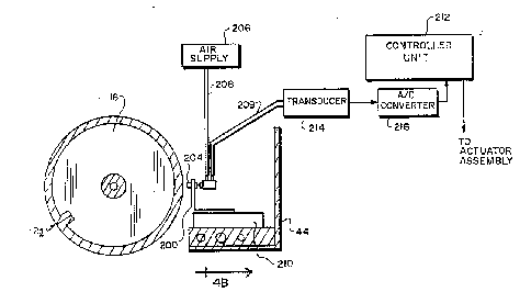
Fig. 4A is a schematic depiction of the preferred
emho~lir-nt of our tracking system. The pneumatic sensing
apparatus is mounted on a slide 200, which is itself affixed to
carriage 44 (shown in FIG. 3). Writing head 56 ~see FIG. 5) is
positioned on sliae 200 above, below or to either side of
sensor head 204. Slide 200, along with the apparatus mounted
thereon, is attached to base support 210.
In this Pmho~;r L, sensor head 204 is equipped both to
deliver a regulated air f low that generates the measurement
signal, and to sense the reflected pressure or airflow signal.
The measurement pressure signal is emitted by sensor head 204,
which is supplied with air by means of flexible tubing 208
connected to a regulated air supply 206. The resultant
reflected pressure signal is coupled through tubing 209 and
measured by a yL~S_ULe tr7lnc~ Pr 214 whose output is digitized
by analog-to-digital (A/D) converter 216 and supplied to a
controller unit 212.
We have obtained good results using applied pressures of
1.0 to 2.5 psig at a constant flow rate of approximately 15
liters/minute. However, it should be understood that
advantageous results could be obtained by using a gas other
than air and with different pressure/flow rate combinations, as
would be well within the skill of an ordinary practitioner to
determine .
As noted above, it is not necessary for gas to be expelled
WO92/01567 PCI/US91/04206
,, ~ _ ~
i~ 2065850 ~
from port 230; it can instead be drawn through port 230, with
u~e tr~n~dl~cpr 214 then measuring the magnitude of the
resultant vacuum.
In the following discussion, elements and steps related to
the distance-sensing assembly are described in terms that
assume use of the preferred configuration outlined above;
however, it should be understood that all operative
configurations are intended to be covered hereby, with such
changes as are rendered necessary by alterations in desiQ,n of
the distance-sensing assembly. I~ particular, for ease of
description, we will describe a constant-~low configuration for
air supply 206, with the intention of implying correlative
features and characteristics of a constant-pressure system.
Thus, instead of measuring pressure as an indicator of
distance, we derive distance from the airflow necessary to
maintain a constant pressure.
The construction of the preferred sensor head 204 is
shown with greater particularity in FIGS. 4B and 4C, which
depict front and side schematic views thereof. The measurement
pressure signal, provided by air supply 206 through tubing 208,
issues from sensor head 204 through an annular port 230. The
resultant pressure at port 232, whlch occupies the center of
port 230, propagates arong the interior of flexible tubing 209
to a pressure transducer 214. Prassure transducer 214 converts
the sensed pressure into an electrical signal that is directly
related to the magnitude of the pressure at transducer 214,
which pressure, in turn, is a function of the pressure at port
230. Transducer 214 thus generates an electrical signal that
is responsive to the pressure that prevails at the orifice.
This electrical signal is transferred to an A/D
converter 216, which applies a digitize~ representation thereQf
to controller unit 212, described below; controller unit 212
performs the processing and evaluation tasks that determine
whether an adjustment to the etch gap is necessary. If so, it
sends appropriate signals to the actuator assembly, which makes
_ _ _ _ _ _ _ , _ . . . . , . . .. . .. _ . . . . _ _
WO92/01567 PCI/US91/04206
20658~ 7~
the nPrpcsAry distance adjustment.
The dimensions of sensor head 204 are dictated by
functional considerations. The sensor should provide accurate
readings to at least 0.007 inch from plate surface 13.
nce is related to distance as a single-valued function,
preferably (although not nprpccArily) linearly in order to
facilitate straightforward calculation. Furthermore, the slope
of the response as a function of distance should be gradual in
order to assure a sufficient working range. Small size is also
desirable in order that the sensor head may be positioned close
to writing head 56, thereby increasing the accuracy of distance
measurements .
The annular orif ice design is well-suited to achieving
these objectives. Because annular port 230 emits a symmetrical
sleeve of air, any pressure drop at port 232 caused by the
emitted air will vary directly with distance to plate surface
13 over a greater range of distances than would be possible
using alternative designs. The annular design is amenable to
manufacture in small dimensions, allows the sensor to deliver a
gradual response as a function of distance, and reduces
measurement inaccuracies of irregular surface features. For
example, we have advantageously employed a sensor produced by
Festo Corp. of Hauppauge, New York, that provides an annular
orif ice of approximately 0 . 01 inch width in a sensor element
0 . 2 inch across .
Refer now to FIG. 5. As shown therein, the actuator
assembly consists of a stepper motor 215 having a track serv~
cam 217. A cam follower 218 is mounted on a slide 200 which
moves toward and away from plate cylinder 16. The slide rests
on 6tationary base support 210. (These _ -nPnts were omitted
for clarity from FIG. 4A). In response to signals from
controller unit 212, stepper motor 215 rotates cam 217 t~.rough
a sufficient angular distance to displace cam follower 218, and
hence slide 200 (to which are affixed writing head 56 and
sensor head 204 ) the requisite linear distance . Slide 200 is
WO 92/01567 PCI /US91 /04206
-18-`~ 206585~ .
normally uryed toward plate cylinder 16 by spring 220, the
other end of which is mounted to stationary base support 210.
Preferably, the surface of cam 217 comprises two spiral:
segments and a dwell segment, and cam follower 218 is
prefQrably a ball-bearing type follower. In the Pmh~ nt
depicted in FIG. 5, the dwell segment represents the highest
point of the cam, since rotation of the cam toward the dwell
segment draws slidQ 200 away from plate cylinder I6. In an
e~pe~ lly preferred Pmhorlir-nt, illustrated in FIG. 7, the
first spiral segment occupies 90 degrees of the cam
circumference; this segment is used to withdraw writing head 56
from impression cylinder 16 (i.e. to the dwell position) when
the tracking system is inactive. In this embodiment, the
second spiral surface, which occupies approximately 200 degrees
of the cam circumf~erence, has a radial increase of 0. 0001 inch
for each 0.9 degreQs of cam rotation; stepper motor 215 is
chosen such that each 0 . 9 degrees of cam rotation represents
one half-step.
While the actuator assembly described above is a
preferred P~ho~lir ~, other means of actuation can be employed
~s well. Such means may include, for example, DC servomotors,
pneumatic actuators, hydraulic actuators, voice coil actllators,
~nd other systems that impart linear or rotary actuation
motion .
Controller unit 212 preferably consists of an analog-to-
digital (A/D) converter and standard microprocessor-based servo
control circuitry. The computer program that directs the
operations of controller unit 212 is stored in read-only memory
(ROM) or other suitable permanent-storage device. An
appropriate amount of random-access memory (RAM) is also
provided to facilitate program execution. Controller unit 212 :
is ~L~JyLallUlled for three modes of operation: park, calibrate
and track.
In the park mode, which is initiated both when the unit
i~ activated and after a plate is imaged, cam 217 is rotated
W092/01567 PC~ S91/04206
.
-19- 2~ 8 5
into the dwell position. When the top of the dwell segment is
reached, a one-bit status flag (the ~park flag~') is set to its
"on" state. The park mode is triggered by a signal from main
system controller 50 (shown in FIG. 3).
Before printing is _ ~nced on a newly mounted plate, a
calibration operation must be performed to orient the tracking
system. Calibration is initiated in response to a calibration
signal provided by main controller 50; this signal is asserted
when the unit is initially turned on, as part of the start-up
sequence. Calibration will not start unless the park flag is
set (thus providing assurance that writing head 56 has been
withdrawn from plate surface 13), the park signal no longer
asserted (confirming that the start-up sequence has, -nr~d),
and plate cylinder 16 is positioned such that the plate-
clamping area or "void" (denoted by reference numeral 12a) is
not under sensor head 204.
The first step in the calibration sequence is movement
of cam 217 along the second spiral surface until contact is
made between electrode tip 58k and plate surface 13. The
amount that cam 217 must be rotated to assure contact is
determined during manufacture, and this value permanently
stored within controller unit 212. In response to the
calibration conditions described above, controller unit 212
issues to stepper motor 215 the signals necessary to obtain the
contact position.
Next, writing head 56 is withdrawn slightly from plate
surface 13 to establish a baseline value representing the
closest allowable distance. This is accomplished by turning
stepper motor 212 a step at a time until a pressure change is
detected by sensor head 204, which indicates that electrode tip
58k is no longer in contact with plate surface 13. In order to
allow for r--h~ni~Al fluctuations and plate surface features,
stepper motor 212 is turned an additional number of fixed
steps, such that electrode tip 58k is further withdrawn from
plate surface 13 but remains well within the useful operating
-
WO 92/01567 ~ PCI /US91/04206
`20b58S0 -20-
range for spark-discharge recording.
Having established a bACol inP value, the control program
then causes stepper motor 215 to turn in half-step increments.
With each half -step, the ref lected pressure signal produced by
pL~SDU~ tr~n~ Pr 214 is transmitted to analog-to-digital
converter 216 and digitized. In order to enhance system
accuracy, a number of pLc:ssuLe: readings are taken and averaged.
The averaged digital value is stored in a correlation table
that relates a 60urce-to-plate distance (which is permanently
stored in ROM, having been calculated from the step size of
stepper motor 215, the number of steps turned by the stepper
motor, and the curvature of the second spiral surface of cam
217) to each successive digital value. The stepper motor is
stepped, and additional values entered into the correlation
table, over the entire useful etch-gap value range.
Upon receiving a tracking signal from main controller
50, controller uni'c 212 begins the track sequence. It is not
necP~ry for tracking to begin at the calibration site. The
track sequence begins with retrieval of a predetermined etch-
gap index value, which reflects the preferred etch gap for the
particular plate in use. The operator or main controller 50
can supply this value, depending on the degree to which the
pre6s or platemaker is automated. Controller unit 212 locates
the entry in the correlation table closest to the etch-gap
index, and actuates stepper motor 215 until the ple:s:~u~:
reading corresponding to the distance closest to this etch-gap
distance is reached. Alternatively, controller unit 212 can be
configured to compare the current etch-gap distance (as
detPrm;necl by sensor 204) with the etch-gap index value,
calculate the number of steps of stepper motor 215 npcpc~:Ary to
reach the index value, and cause executi~n of such steps.
Spark-discharge recording then begins. A/D values are
constantly acs~uired and averaged (approxima~ely eight times per
millisecond in the preferred PmhoS;~ -rt), and the averaged
values compared with entries in the correlation table created
~ WO 92/01~67 ~ Pcr/usgl/04206
-21- 206585~ - -
during calibration to verify that the etch-gap distance remains
at the index value. Any deviation therefrom causes a
comparison to be made between the observed pressure value and
the value COLLI'~ I""lA;n,r~ to the etch-gap index; the number of
entries in the correlation table separating these two values
then represents the number of steps n~rP-:C Ary to correct the
discrepancy. Alternatively, the observed ~Les~uL~ can be
converted directly into its associated distance value, and this
distance compared to the etch-gap index value. Any
differential is then translated into a corresponding pressure
difference, and sensor 204 moved until this pressure difference
is achieved.
As hereinabove noted, main controller 50 maintains
"awareness" of the instantaneous angular position of impression
cylinder 50. When void 12a arrives at a position opposite
electrode 58, main controller 50 provides a trigger signal to
controller unit 212, which causes writing head 56 to be
withdrawn a predetermined distance until the void section has
passed. Main controller 50 similarly signals the end of void
12a and concomitant reappearance of imageable plate surface.
Referring now to FIG. 3, the writing head 56, and
particularly the pulsing of its electrode 58, is controlled by
a pulse circuit 96. One suitable circuit comprises a
transformer 98, the sPc~n~l~ry winding 98a of which is connected
~t one end by way of a variable resistor 102 to terminal 64a
which, as noted previously, is connected electrically to
electrode 58. The opposite end of winding 98a is connected to
electrical ground. The transformer primary winding 98k is
connected to a DC voltage source 104 that supplies a voltage in
the order of 1000 volts. The transformer primary circuit
i nrll-AP~3 a large capacitor 106 and a resistor 107 in series .
The c~pacitor is maintained at full voltage by the resistor
107. An electronic switch 108 is connected in shunt with
winding 98k and the capacitor. This switch is controlled by
switching signals received from controller 50.
WO 9Z/0l567 PCr/US91/04Z06
~ 22-
It should be understood that circuit 96 a5 BpeCif ically
illu6trated is only one of many known circuits that can be used
to provide variable high-voltage pulses of short duration to
electrode 58. For example, a high-voltage switch and a
capacitor-regenerating resistor may be used to avoid the need
ror transformer 98. Also, a bias voltage may be applied to the
electrode 58 to provide higher voltage output pulses to the
electrode without requiring a high- voltage rating on the
~witch .
When an image is being written on plate 13, the press 10
is operated in a non-print or imaging mode with both the ink
and water rollers 22_ and 26_ being fiicon~aged from cylinder
12. The imaging of plate 13 in press 10 is controlled by
controller 50 which, as noted previously, also controls the
rotation of cylinder 12 and the &clnnin~ of the plate by
carriage assembly 42. The signals for imaging plate 13 are
applied to controller 50 by a conventional source of picture
signals such as a disk reader 114. The controller So
synchronizes the image data from disk reader 114 with the
control signals that control rotation of plate cylinder 12 and
movement of carriage 44 so that when the eiectrode 58 is
positioned over uniformly spaced image points on the plate 13,
switch 108 is either closed or not closed dependlng upon
whether that particular point is to be written on or not
written on.
If that point is not to be written on, i . e. it corresponds
to a location in the background of the original document, the
electrode is not pulsed and proceeds to the next image point.
On the other hand, if that point in the plate does correspond
to a location in the printed area of the original document,
switch 108 is closed. The closing of that switch discharges
capacitor 106 so that a precisely shaped, i.e. squarewave, high
voltage pulse, i.e. 1000 volts, of only about one microsecond
or less duration is applied to transformer 98. The transformer
a~plies a stepped up pulse of about 3000 (or more) volts to
~ WO 92/01567 ~e~/US91/04206
~b65~50 23
electrode 58, causing a spark discharge S between the electrode
tip 58_ and plate 13. That sparks and the accompanying corona
field S' ~ùL~-~u~-ding the spark zone etches or transforms the
surface of the plate at the point thereon directly opposite the
electrode tip 58_ to render that point either receptive or non-
receptive to ink, ~rPn~l i n~ upon the type of surf ace on the
plate .
Resistor 102 is adjusted for the different plate
Pmhorlir-rlt5 to produce a spark discharge that writes a clearly
defined image spot on the plate surface which is in the order
of 0 . 0001 to 0 . 005 inch in diameter. That resistor 102 may be
varied manually or automatically via controller 50 to produce
dots of variable size. Dot size may also be varied by varying
the voltage and/or duration of the pulses that produce the
spark discharges. ~leans for doing this are quite well known in
the art. Likewise, dot size may be varied by repeated pulsing
of the electrode at each image point, the number of pulses
detPrm;n;n~ the dot size (pulse count modulation). If the
electrode has a pointed end 58_ as shown and the gap between
tip 58_ and the plate is made very small, i.e. 0.001 inch, the
spark discharge is focused so that image spots of 0 . oOl inch
diameter, more or less, can be formed while keeping voltage
requirements to a minimum. The polarity of the voltage applied
to the electrode may be positive or negative although
preferably, the polarity is selected according to whether ions
need to be pulled from or repelled to the plate surface to
effect the desired surface transformations on the various
plates to be described.
As the electrode 58 is scanned across the plate surface,
it can be pulsed at a maximum rate of about 500,000 pulses/sec.
However, a more typical rate is 25,000 pulses/sec. Thus, a
broad range of dot densities can be achieved, e.g. 2,000
dots/inch to 50 dots/inch. The dots can be printed side-by-
side or they may be made to overlap so that substantially lo
of the surface area of the plate can be imaged. Thus, in
-
WO92101~67 PCI/llS91/04206
., .,
24-;~ 8~;0
response to the in-~o~in~ data, an image corrPCp~n~in~ to the
original document builds up on the plate surface constituted by
the points or 6pots on the plate surface that have been etched
or transformed by the spark discharge S, as compared with the
areas of the plate surface that have not been so affected by
the spark discharge.
In the case of axial cC~nn;n~, then, after one revoIution
of plate cylinder 12, a complete image will have been applied
to plate 13. The press lo can then be operated in its printing
mode by moving the ink roller 22_ to its irking position shown
in solid lines in FIG. 1, and, in the case of wet printing, by
~lso shifting the water fountain roller 26k from its-dotted
line position shown in FIG. 1. As the pIate rotates, ink will
adhere only to the image points written onto the plate that
correspond to the printed portion of the original document.
That ink image will then be transferred in the usual way-via
blanket cylinder 14 to the paper sheet P mounted to cylinder
16 .
Forming the image on the plate 13 while the plate is on
the cylinder 12 provides a number of advantages, the most
important of which is the significant decrease in~ the
preparation and set up time, particularly if the invention is
incorporated into a multi-color press . - Such a press includes a
plurality of sections similar to press 10 described herein, one
for each color being printed. Whereas normally the plate
cylinders in the different press sections after the first are
ad~usted axially and in phase so that the different coIor
i~ages printed by the lithographic plates in the various press
sections will appear in register on the printed copies, it is
apparent from the foregoing that, since the images are applied
to the plates 13 while they are mounted in the press sections,
6uch print registration can be accomplished electronically in
the present case.
I~ore particularly, in a multicolor press, incorporating a
plurality of press sections similar to press lO t the controller
WO92/01567 ~. PCT/US91/0420~i
2065:~5(~ -25-
50 would adjust the timings of the picture signals controlling
the writing of the images at the second and subsequent printing
sections to- write the image on the lithographic plate 13 in
each such station with an axial and/or angular offset that
~ ates for any misregistration with respect to the image
on the f irst plate 13 in the press . In other words, instead of
achieving such registration by repositioning the plate
cylinders or plates, the registration errors are accounted for
when writing the images on the plates. Thus once imaged, the
plates will automatically print in perfect register on paper
sheet P.
Although writing head 56 is depicted in FIG. 3 as
consisting of a single electrode 58, such a simple
conf iguration places signif icant limitations on the speed with
which a plate can be imaged . One means of DYr~n~l; ng the
capabilities of the present invention is to use a writing head
containing a plurality of imaging styli. The image data must
then be divided into parallel rows of vertical points, in the
case of circumferential scanning, or horizontal points in the
case of axial scanning. Data from multiple rows are then
simultaneously fed to all styli, each of which produces a
single row of image dots. After the multiple-stylus head has
made a complete revolution around (or axial traverse of ) the
impression cylinder, the head is moved to a position that is
displaced from the original starting point by the number of
rows that have already been imaged.
The most obvious configuration for a multiple-electrode
arrangement would involve a single horizontal or vertical row
of imaging electrodes. However, the proximity of each
electrode to its neighbors is limited by the effect of
simultaneous spark discharges. If the electrodes are spaced
too closely, simultaneous arcing would cause unwanted
interaction, resulting in deterioration of image ~uality.
However, we have found that the effectlve distance between
styli can be minimized by displacing the styli from one another
WO 92/0l56~ ~ ~ ~ PCr/US91/04206
-26- -20658:5Q
=
in the direction of imaging, resulting in a diagonal ro~ cf
styli. In the following discussi4n, we describe a multiple-
6tylus array that images vertically; in the preferred
r~mhoAir-~t, this corresponds to the direction of plate cylinder
12 rotation . Although this conf iguration provides the simplest
and fastest imaging means, since the impression cylinder can bè
rotated continuously and the writing head simply shifted,
translated axially after each set of vertical rows is scanned,
an analogous arrangement could be employed f or imaging in the
axial direction.
Reference numeral 56 in FIG. 6A denotes generally a
suitable multiple-stylus writing head. The lead from each of
the electrodes (designated collectively by reference numeral
250) is directed to a contact along array 252. Each contact
ultimately connects to main controller 50, which can either
receive image data already arranged into vertical rows, Qr can
be adapted for sampling the contents of a memory buffer
containing a complete bitmap representation of the image and
transmitting appropriate signals to each electrode as it ~
traverses positions along the impression cylinder corresponding
to bitmap points.
A front view of electrode array 252 is shown in FIG. 6B.
The electrodes must be spaced far enough from one another to
prevent arcing therebetween. We have obtained good results
when the electrodes are spaced approximately 0. 05 inch away
from one another, but a range of interelectrode distances will
satisfy the foregoing criterion. Thus, in order to maintain
the electrodes at a horizontal distance of about 0. 001 inch
from one another, the vertical pitch in our preferred
r~hoAi-- t is 0.05 inch.
- After each revolution of the plate cylinder, the array is
advanced along the cylinder ' s axis by a distance equal to the
product of the number of wires in the array and the axial pitch
between the wires.
In some situations, imaging speed can be enhanced even
WO 92/01567 PCr/US91/04Z06
-
~06585a-- -27- - ~,
further by use of a plurality of multiple-stylus writing heads.
However, such arrangements cannot ordinarily be used for si~gle
composite images. Not only are the unimaged strips that result
from the gap between adjoining heads cumbersome to scan, but
these atrips can become electrically isolated from the
rr--inrl~r of the plate; electrical isolation preYents
maintenance of the ground necessary for imaging. Thus, more
than one multiple-stylus head may be employed to print in
strips (such as would be useful for printing labels or tickets)
where adjacent imaged areas do not overlap, and a non-imaged
space remains between adjacent imaging areas.
The length of each electrode is determined by its
position within array 252 and the curYature of plate cylinder
16. Array 252 forms an arc which aligns with the plate
surface. The linear dimension of each electrode must be
controlled precisely during assembly because, as has been
stressed hereinabove, the gap between the electrode tip and the
plate surface is critical.
By themselves, properly measured electrode tips do not
furnish the necessary alignment of array 252 with plate
cylinder 16. The entire writing head 56 must align
circumferentially with the curvature of the plate cylinder 16
in order to maintain a constant etch gap. In addition, the
plane of array 252 must remain at the "correct" angle with
respect to the axis of plate cylinder 12, both to prevent
adjaGent passes oYer the plate surface from overlapping or
leaving a perceptible gap therebetween, and to maintain the
desired horizontal pitch between the electrodes. In this
context, the "correct" angle means the deviation of the plane
of the array of electrodes from a plane perpendicular to the
axis of plate cylinder 16, denoted as e in FIG. 6B, such that
the body of writing head 56 is substantially perpendicular to
said axis.
We have developed a pitch-and-roll adjustment assembly,
shown in FIG. 5, for use with the present invention that
WO 92/01567 PCr/US91/04206
-28~
facilitates fine adjustment of the position of writing head 56
along two axes. This assembly consi6ts of an advantageously
configured flexure plate and associated mounting c ~onPnts.
As shown in FIG. 5, fl~xure plate 260 is secured to base
support 210 by means of screws 268 and 274. To flexure plate
260 is attached writing head support 270, which serves as the
base for writing head 56. Flexure plate 260 is formed from a
single metal plate and is fabricated with grooves extending
substantially more than halfway through its thickness. -These
grooves run in directions parallel and perpendicular to
impression cylinder 16, and allow the plate to bend in a
predictable fashion, through a limited arc, about the roll and
pitch axis without deformation. ~Jack screws 262 and 264 are =
used to set and maintain the desired roll and pitch,
respectively .
Flexure along the pitch axis, which is facilitated by at
least one groove in f lexure plate 260 extending along the pitch
axib, controls the pitch angle of writing head 56 so as to
align it with the ~late cylinder 16 surface. A high degree of
stiffness is maintained along all other directions.
Positioning the flexure plate about the pitch axis is
accomplished by means of pitch adjustment screw 264, which is
threaded through flexure plate 260 and tracking slide 2~0 to
which it is mountGd by attaching screws 268 and 274.
In order to enhance the fineness of pitch adjustment,
adjustment screw 264 can be provided with two threaded portions
on two different diameters along its length. The screw~ pitch
on the smaller-diameter portion is f iner than that on the
larger-diameter portion. One portion is threaded into the
tracking slide 20C and the other portion is threaded into
flexure plate 260. As adjustment screw 264 is turned into
flexure plate 260, the finer pitch advances less then the
coarse pitch, such that flexure plate 260 is spread from
tracking slide 200 but by a lesser amount than the pitch
advance of either screw portion.
WO92/01567 - -- - PCI/US91/0~1206
206585~ -29-
Writing head 56 i5 secured to image head support 270,which is mounted to flexure plate 260 by attaching screws 280.
Roll is facilitated by flexure across at least one groove in
flexure plate 260 extending along the roll axis. The degree of
roll is controlled by means of roll adjustment screw 262, which
i5 threaded through image head support 270 and the flexure
plate 260. As adjustment screw 262 is turned, the angle of
image head support=270 with respect to the plate cylinder axis
i5 altered, thereby causing writing head 56 to rotate along the
roll axis. Furthermore, the fineness of roll adjustment can be
enhanced by use of two threaded portions differing in pitch
along roll adjustment screw 262, as described above in
connection with pitch adjustment screw 264. In a multiple-
stylus configuration, the roll action alters the angle of the
array with respect to plate cylinder 16, thereby varying the
effective distance between electrodes as presented to plate
cylinder 16.
The terms and expressions which have been employed are
used as terms of description and not of limitation, and there-
ïs no intention, in the use of such terms and expressions, of
excluding any equivalents of the features shown and described
or portions thereof, but it is recognized that ~arious
modif ications are possible within the scope of the invention
claimed. For example, although we beliQve that the preferred
s~Tnh9r~ nt of our tracking system offers a highly advantageous
solution to all of the constraints associated with spark-
discharge imaging, it may be possible to adapt alternative
sensing technologies for use with our imaging system. Such
alternative technologies might include proximity monitoring
based on capacitance, optical, eddy-current or magnetic
characteristics .
s~
,_
.
_,