Note: Descriptions are shown in the official language in which they were submitted.
~0~~~2~
AU~1409
1
V-RIBB~~~
Back round of the Tnvention
Field of the, Invention
This invention relates to power transmission belts
and, more particularly, to a belt with longitudinally
extending, laterally spaced ribs and discrete, laterally
directed reinforcing fibers in both the tension and
compression sections of the belt in which a) cracking
between adjacent ribs is minimized without significantly
l0 altering the flexibility of the belt and b) a high
friction drive surface is provided on the back/outside
surface of the belt.
Backaround,_ Art
Power transmission belts having a plurality of
laterally spaced, longitudinally extending, V-shaped ribs
have a wide range of applications in many diverse fields.
These belts, commonly referred ae V-ribbed belts, are
used, for example, in the automotive industry, on
agricultural implements, on domestic electrical
implements, and Surther on general purpose equipment.
V-ribbed belts have a number of desirable features.
Because the v-ribbed belt is normally thinner than a
conventional V-belt, it is highly flexible and thus
capable of wrapping around pulleys of relatively small
diameter. v-ribbed belts are commonly used in What are
known as serpentine drive systems on automobile engines.
The belt is wrapped in a circuitous path so that engine
components are driven by both the inside and autside
surfaces of the v-ribbed belt. The flexibility of the
belt allows the various components driven thereby to be
co~apactly situated. This is particularly desirable in an
~4~5~2~
ALA-14 09
2
automobile engine compartment in which space is at a
premium.
The V-ribbed belt is also desirable for its energy
saving capability. This is due in part to the highly
flexible nature of the V-ribbed belt.
A still further advantage of the V-ribbed belt is
that the individual ribs do not penetrate the grooves in
a cooperating pulley as deeply as those in a convantianal
V-belt drive system. By minimi2ing the friction between
i0 the belt and pulley as the belt engages and disengages
from the pulley, abrasive wear on the belt is reduced
over conventional V-belts. Further, less tension is
required to be applied to the belt during operation. The
advantages of this are both a savings in energy during
operation and prolongation of the belt life.
All of the above features make the V-ribbed belt
desirable in the wide range of industries in which it is
currently being used.
The V»ribbed belt, however, does have a number of
drawbacks. One problem is encountered with the v-ribbed
belt in a serpentine drive system in which both the
inside and outside surfaces of the belt are used for
driving purposes. The outside surface of the belt, which
is typically Flat, i.e, without ribs, facially engages an
annular surface on a pulley to be driven by the belt. To
reinforce the outside surface of the belt, typically the
exposed outer surface is defined by a rubber-coated
fabric. However, the fabric, while reinforcing the
outside of the belt, reduces the coefficient of friction
on the outside belt driving surface and results in the
belt slipping relative to the pulley, which thereby
reduces the power transmission capability of the
back/outside surface of the belt.
One solution to this problem is to define the
exposed outer surface by a rubber layer. This improves
~~~~~~$
FLU-14 09
3
the power transmission capability of the back/outside
surface of the belt. However, the unreinforced outside
rubber layer is prone to cracking, particularly where it
laterally coincides with the troughs between adjacent
ribs, where the belt is the thinnest. A crack that
originates in the rubber layer may propagate freely.
There is a resulting tendency of the ribs to break away
from each other at the relatively thin portion or the
belt between ribs.
l0 In addition to the above problems noted for V-ribbed
belts using a rubber-coated fabric in the back/outside
surface thereof, such belts further require multiple
components, which adds to the cost of manufacture. For
example, a conventional bslt made according to the above
15 may require Pour different components: 1) rubber coated
fabric; 2) load-carrying cords; 3) reinforcing fibers for
the compression section; and 4) at Least one rubber
composition for the tension section, compression section
and load-carrying section defining the neutral belt axis.
20 There is yet another problem resulting from the use
of a rubber-coated fabric on the back/outside surface of
the belt. Tha rubber-coated fabric requires the
formation of a joint to produce an endless band from the
rubber-coated fabric, rn addition to the difficulty in
25 producing a high integrity joint, the
joint itself may
produce a locali2ed variation in the belt thickness.
This variation may induce vibrations to the system and/or
may result in inconsistent drive characteristics.
Further, the belt is prone to failure at the joint, which
30 could make the belt unusable.
~ummarv of the Invention
The present invention is specifically directed to
overcoming the above-enumerated problems in a novel and
simple manner.
2~~~~~~
AU-1409
4
According to the invention, a power transmission
belt having an inside surface and an outside surface is
provided. fhe power transmission belt has: a compression
section defining a plurality of laterally spaced,
longitudinally extending ribs made at least partially of
rubber; a plurality of discrete, laterally extending
reinforcing fibers in the ribs: a tension section outside
of the compression section and defined at least partially
by a rubber layer; and a plurality of discrete, laterally
extending reinforcing fibers in the rubber layer of the
tension section. The length of the reinforcing fibers in
the rubber layer of the tension section is greater than
the length of the reinforcing fibers in the ribs.
According to the invention, the reinforcing fibers
in the rubber layer of the tension section reinforce the
rubber to minimize cracking, as between adjacent ribs,
without significantly altering the flexibility of the
belt. Preferably, the rubber layer in the tension
section defines tha exposed outside surface of the belt
z0 which, in certain systems, sexves as a pulley-engaging
drive surface. The fibers in the rubber layer in the
tension section do not significantly alter the drive
characteristics of the back/outside surface of the belt.
In one forts of the invention, the reinforcing fibers
in the rubber layer of the tension section are at least
1.5 times as long as the reinforcing fibers in tha ribs.
In one form, the length of the reinforcing fibers in the
rubber layer of the tension section is in the range of 5
to 20 mm and more preferably in the range of l0 to 15 ~nm.
The reinforcing fibers in the ribs have a length
preferably in the range of 3-10 mm.
With the reinforcing fibers in the rubber layer of
the tension section, the tension section can be made
relatively thin so as to provide a highly flexible belt
that is not prone to cracking, even at its thinnest
2~~~~28
AU-1409
points betwe~n adjacent ribs. The fibers also prevent
propagation of any crack that might develop in the belt.
In one form, the rubber layer of the tension section has
a thickness of between 0.3 and 5.0 mm and preferably is
5 in the range of 0.5 amn and 2.0 aim.
To optimize both reinforcement of and driving
capability for the back/outside surface of the rubber
layer in the tension section, the reinforcing fibers are
distributed in the rubber layer in the tension section in
the amount of 1 to 50 weight parts of reinforcing fiber
to 100 weight parts of rubber.
In one form, the reinforcing fibers in the ribs are
mixed in the amount of 5 to 30 weight parts of
reinforcing fiber to 100 weight parts of rubber.
In one form, the reinforcing fibers in the rubber
layer of the tension section are made at least partially
of synthetic fiber yarns that are at least one of nylon,
vinylon, polyester and aromatic polyamide. The invention
also contemplates the reinforcing fibers in the rubber
layer of the tension section to be made at least
partially of a mixture of yarns that are made of natural
fib~r yarn that is one of cotton and pulp, etc., mixed in
a predetermined ratio with synthetic fiber yarns, as
described above.
In one form, a cushion rubber layer is provided and
has lead-carrying cards embedded therein to define a
neutral axis gor the belt. The load-carrying cords are
preferably made from at least one of polyester, nylon and
aromatic polyamide.
In one form, the rubber in at least one of a) the
ribs, b) the rubber layer in the tension section, and c)
the adhesive rubber layer, is apt least one of NR, SBR,
CR, and H~1BR. Tn a preferred form, the rubber making up
at least two of a) the ribs, b) the rubber layer in the
tension section, and c) the cushion layer is the sane.
AU-1409
6
In one form of the invention, there are no laterally
extending reinforcing fibers in the cushion rubber layer.
With the present invention, not only are belt
performance arid life improved, but manufacturing is
facilitated by reducing the number of belt components.
In one form of the invention, the same rubber can be used
for the ribs, cushion rubber layer and the rubber layer
in the tension section. The reinforcing fibers in the
rubber layer in the tension section and ribs can be made
l0 from the same material. The only other required
component is the cord structure used to define the
longitudinally extending, load-carrying cords. As a
result of simplifying manufacturing, the costs attendant
thereto are reduced.
Further, by excluding the rubber-coated fabric
layer, in addition to the other advantages noted above,
the point at the free ends of the fabric, normally
required to produce a conventional belt, can be
eliminated.
Further, by having the tension rubber layer with
reinforcing fibers therein, the exposed back/outside
surface of the belt can be ground and polished to a very
uniform surface so that the belt thickness does not
deviate over the entire belt length, resulting in a
consistently high quality belt. Smooth and consistent
operation of the belt result. Also, the possibility of
failure of the fabric joint is eliminated.
brief Description of the Drawings
Fig. 1 fe a crass-sectional, perspective view of a
section of a V-ribbed belt of the prior art and utilizing
rubber-coated fabric to define a back/outside driving
surface therefor:
2~~~~~8
AIJ-14 09
7
Fig. 2 is a cross-sectional, perspective view of a
section of a v-ribbed belt according to the present
invention; and
Fig. 3 is a schematic, side elevation view of a
horsepower testing machine for power transmission belts.
Detailed Description of the Drawings
In Fig. l, a prior art, V-ribbed belt is shown at
10. The belt 10 has a load-carrying section 12, defining
a neutral axis for the belt, a compression section 14,
to and a tension section 16. A single rubber layer 18
defines a cushion layer 17, in which a plurality of
longitudinally extending, Load-carrying cords 20 are
embedded. The rubber layer 18 is contiguous with the
tension section 16 and compression section 14. Two
rubber-coated fabric layers 22, 24 are adhered to the
outer surface 26 of the rubber layer 18. Only one such
layer 22, 24 is required. The outer fabric layer 24
defines the exposed back/outside surface 28 of the belt
10 which i~ directly engageable With a pulley with the
2o belt l0 used as in a serpentine drive system. Alterna-
tively, the layer 24 can be made entirely of rubber
without any fabric reinforcement.
The rubber coated fabric layers 22, 24, by reason of
incorporation of the fabric 30 therein, become relatively
rigid, which detracts from the overall flexibility of the
belt 10. At the same time, the exposed fabric 30 reduces
the coefficient of friction of the outside surface 28 of
the outer layer 24 to compromise its drive capabilities.
A still further problem with the belt l0 in Fig. 1
is that the fabric 30 must be joined at a seam/joint 32
to define ar. endless fabric band. This seam/joint 32 can
be made by any of a number of techniques known to those
skilled in the art. ~Iowever, regardless of the technique
used to define the seam/joint 32, there is a possibility
Au-1409
8
that there will be a variation in the thickness of the
layers 22, 24 at the seam 32, particularly when the free
ends of the fabric 30 are overlapped. Punong other
potential problems resulting from this localized
thickening, there is the potential for rough operation of
the belt, which may induce vibrations to the system.
A further problem with the seam 32 is that it is
normally a weakened portion of the fabric 30. If the
seam 32 fails, the fabric layer 24 could Come apart and
to render the belt unusable .
As previously noted, elimination of the-fabric 30
from the rubber in the layers 22, 24, while providing a
high coefficient of friction for the back/outside drive
surface 2s, may result in cracking of the belt above the
troughs 34, 36, defined between adjacent ribs 38, 40 and
40, 42, respectively. As can be seen, the belt 10 has a
relatively thin dimension in lateral coincidence with the
troughs 34, 36. Cnca a crack starts in the layers 22, 24,
there is little to prevent it from propagating.
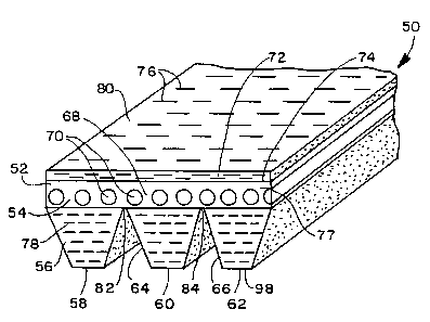
A preferred form of the inventive belt is shown at
50 in Fig. 2. The belt 50 is a V-ribbed belt having a
tension section 52, a load-carrying section 54, and a
compression section 56. The belt 50 has a plurality of
longitudinally extending, laterally spaced, V-shaped ribs
58, 60, 62, with V-shaped grooves 64, 66 defined
respectively between the ribs 58, 60 arid ribs 60, 62 for
reception of cooperating pulley teeth (not shown).
The load-carrying section 54 has a cushion rubber
layer 68 within which a plurality of longitudinally
extending, load-carrying cords 70 are eanbedded. The
cords 70 are made of low elongation, high strength
material. In a preferred form, the cords 70 are made of
at least one of polyester, nylon and aromatic polyamide
giber. The cushion rubber layer 68, in which the load-
carrying cords 70 are embedded, is preferably made either
2~~~~9~8
AU-1d09
9
solely from NR, SBR, CR, and HNBR, etc., or a mixture
thereof.
According to the invention, a rubber layer 72 is
adhered in the tension ssction of the belt 50 to the
outer surface 74 of a rubber layer 77, defining th$
cushion rubber layer 68, which rubber layer 68 is
contiguous with both the tension section 52 and
compression section 56 of the belt 50. Short, discrete,
reinforcing fibers 76 era mixed in the rubber layer ?2
and oriented to extend substantially laterally of the
belt 50.
Short, discrete, reinforcing fibers 78 are also
embedded in the rubber in the compression section 56 and,
in the embodiment shown, are provided only in the ribs
58, 60 and 62. The fibers 78 may be made from a material
that is the same as the material making up the fibers 76.
In a preferred form, the rubber defining the layer
72 is the same as that making up th~ rubber layer 77.
The ribs 58, 60, 62 can also be made from the same rubber
2o material.
According to the invention, reinforcing fibers 76 in
the rubber layer 72 are dispersed in the amount of 1 to
SO weight parts of fiber to 100 weight parts of rubber.
The fiber 76 may be made solely from synthetic fiber
yarns made of nylon, vinylon, polyester, aromatic
polyamide, etc., or a mixture of yarns that are made of
natural fiber that is one of cotton, pulp, etc., mixed in
a pred~termined ratio with the synthetic fiber yarns.
Preferably, the reinforcing fibers 76 are cut to a
length of 5 to 20 min and are more preferably in the range
of to to 15 mm. In any event, the fibers 76 are cut to
be at least 1.5 times as long as the length ~of the
reinforcing fibers 78 in the ribs 58, 60, 62.
The reinforcing fibers 78 are preferably made to
have a length between 3 and 10 mm and are included in an
AU-1409
amount of 5 to 30 weight parts of fibers 78 to l00 weight
parts of rubber in the ribs 58, 60, 62.
The inclusion of the reinforcing fibers 76 in the
layer 72 only minimally diminishes the coefficient of
5 friction of the pulley-engaging outside surface 80 of the
belt 50. At the same time, the reinforcing fibers 76
allow the thickness of the rubber layer 72 to be
relatively small so as not to detract from the overall
flexibility of the belt 50, without significantly
l0 compromising the belt integrity. More particularly, the
rubber layer 72 has a preferred thickness in the range of
0.3 to 5.0 mm, and more preferably 0.5 to 2.0 mm.
The length of the fibers 76 is sufficient to prevent
cracking, particularly at the vertical intersection of
the layer 72 with the troughs 82, 84, defined
respectively between ~ad~acent teeth 58, 60 and 60, 62.
These regions may be highly stressed and thus are
particularly prone to cracking. Stress concentration
over the troughs 82, 84 may result from irregularities in
cooperating pulleys or by reason og misalignment of
cooperating pulleys about which the belt 50 is trained.
A foreign object in a pulley groove may likewise cause
the belt 50 to be highly stressed over the troughs 82,
84. Improved resistance to cracking, which might
ultimately result in separation of the ribs 58, 60, 62,
each from the other, results with the present invention.
Once a crack is developed, the fibers 76 arrest crack
propagation.
If the thickness of the rubber layer 72 is leas than
0.3 m~a, it has been determined that the layer 72 ie prone
to tearing, particularly in the region above the troughs
82, 84. When the thickness of the layer 72 is greater
than 5.0 mm, the overall belt thickness increases to the
point that the desired belt flexibility is lost.
~0~~~28
AU-1409
11
It has been found that if the length of the
reinforcing fibers 76 is less than 5 m~c, no significant
effect is realized in preventing longitudinal tearing of
the layer 72 over the troughs 82, 84. On the other hand,
reinforcing fibers 76 having lengths of 20 mm and over do
not disperse uniformly in the rubber layer 72. That is,
the fibers tend to bend and become randomly oriented
which results in little resistance to cracking of the
layer 72. A crack in layer 72 may propagate through the
layer 77 and result in separation of the ribs 58, 60, 62,
each from the other.
To demonstrate the effectiveness of the device,
tests were conducted comparing variations of the belt 50,
according to the invention, witty conventional belts 10,
as fn Fig. 1.
Te~rina Resistance Test
Inventive Halt
The inventive belt 50 utilized in this test was a K
type belt, as shown in Fig. 2, with four ribs (4PK). 15
parts by weight of short staple reinforcing fibers 7s
made of nylon yarn were mixed per 100 parts by weight of
rubber in the tension rubber layer 72 of the belt 50.
The belt 50 was tested using two different lengths of
reinforcing fibers - 6.0 mm and 12.0 mm. The rubber
layer 72 for each of the inventive test belts was 0.5 mm
thick.
A second test was conducted wherein the reinforcing
fibers were made from aromatic polyamide yarns, rather
than nylon yarns. 5 weight parts of reinforcing fiber
were mixed for each 100 weight parts of rubber. Two
lengths of reinforcing fiber were also tested - 3.0 mm
and 6.0 mm.
~~u~~2~
AU-1409
12
Conventional Belt
The conventional belts 10 tested were the same as
that 10, shown in Fig. 2. The layer 24, in one form, had
n~ reinforcing fibers therein and utilized a rubber-
s coated fabric, while the other belt 10 had an
unreinforced rubber layer 24.
Tae ~ System
The vertical tearing resistance batween the V-ribs
on each belt 10, 50 was measured by a tensile testing
machine having 50 mm/min of pulling speed with two ribs
as a boundary.
The results of these tests are shown in Tables 1 and
2.
TABLE 1
~w~~r wi..~~
Inventive Conventional
Belt Belt
Length of Nylon 6 mat 12 m1n None Fabric
Yarns (Rein-
forcing Fibers)
Vertical Tearing 3.8 4.7 3.0 5.7
Resistance (kgf)
Baak Surface 3.1 3.1 3.3 1.2
Transmission
Capacity (ps)
xw-~.ao9
7.3
TABLE,_2
InventiveConventional
Belt
Selt
Length of 6 mm 3 mm None Fabric
Aromatic
Polyamide Yarns
(Reinforcing
Fibers)
vertical Tearing 4.5 3.2 3.0 5.7
Resistance (kgf)
Back Surface 3.1 3.1 3.3 1.2
to Transmission
Capacity (ps)
A review of the results 1n Tables 1 and 2
demonstrates that the tearing resistance of the inventive
belts 50 is I.2 to 1.6 times as large as that for
conventional belts using rubber alone in the outside
layer 24 without reinforcing fibers. The inventive belts
50 had approximately 0.7 to 0.8 times the longitudinal
tearing resistance compared to the conventional belts i0
using the rubber coated fabric on the outside layer 24.
It was found that the tearing resistance of the
inventive belt was improved by increasing the length of
the reinforcing fibers 76 up to a certain point.
Back Surface Power Transmission Test
Test System
The belts were tested on a device, shown
schematically at 86 in Fig. 3. The testing device 86
consists of an idler pulley 88 and a drive pulley 90,
rotatable about parallel axes 92, 94. The pulleys 88, 90
both had the same diameter of 120 mm. A tensioning
pulley 96, having a 45 mm diameter, was boxne against the
inside surface 98, 98~ of the test belts 10, 50. A
AU-lao9
14
driven pulley 100, having an 85 mm diameter, was utilized
to drive the back/outside surfaces 80, 28 of the belt 10,
50. The system was arranged so that the bending angle
around the driven pulley 100 was equal to 120°-
The system was operated at room temperature with no
load applied to the idler pulley 88 arid tensioning pulley
96. The driven pulley 100 was operated at 4900 rpm with
kgf/3 ribs of belt tension.
The load on the dxiven pulley 100 was varied and
10 noted at the time of 2% slippage for each belt 10, 50.
Conyentional Belt
The same belts ZO were used in this test as in the
tearing resistance test, described above.
entive Bel
15 The V-ribbed belt 50 had three ribs and a length of
1100 mm (3PK1100) and was otherwise constructed the same
as the belts shown in Tables 1 and 2.
The test results are shown in Tables 1 and 2. From
the results, it can be seen that substantially the same
back surface force transmission capability of the
inventive belt 50 is realized using the reinforcing
fibers in the back surface as the conventional belt 10
using a back/outside layer 24 made of rubber with no
short staple reinforcing fibers therein. The back
surface transmission force of the inventive belt 5o was
2.6 times as large as that of the conventional belt 10
using rubber coated fabric.
The foregoing disclosure of specific embodiments is
intended to be illustrative of the broad concepts
comprehended by the invention.