Note: Descriptions are shown in the official language in which they were submitted.
EXPOSURE CONTROL APPARATUS OF CAMERA
BACKGROUND OF THE INVENTION
1. Field of the Invention
The present invention relates to an exposure control
apparatus of a camera, having a plurality of exposure
modes, such as a program exposure mode, a shutter speed
priority exposure mode, and a diaphragm priority exposure
mode, etc., and more precisely, it relates to an exposure
1o control apparatus in which a photographer can set upper and
lower limits of the shutter speed and the diaphragm value.
2. Description of Related Art
In a conventional camera having a plurality of
exposure modes, a photographer can select a desired
exposure mode from a plurality of exposure modes by
actuating an associated switch or button, etc.
In a recent camera having modes other than the
exposure modes, such as a continuous shot mode, etc., the
mode selection is effected by actuating a plurality of
2o switches in combination.
However, ordinary photographers do not frequently use
all of the exposure modes. Namely, only a few specific
exposure modes are used. Therefore, for ordinary
photographers, the need to actuate several switches in
combination to select a mode is troublesome and
1
CA 02065984 1997-12-03
complicated.
Furthermore, in a program exposure mode of a known camera,
a shutter speed and a diaphragm value are automatically
determined in a certain relationship (combination), and
accordingly, it is impossible for the photographer to set
optional shutter speed and diaphragm value which do not satisfy
the predetermined relationship in the same mode. In particu-
lar, if the photographer wants to set a diaphragm value, within
a specific range of diaphragm values, or a shutter speed within
a specific range of shutter speeds, it is impossible for the
photographer to optionally determine the specific diaphragm
value or shutter speed.
The primary object of the present invention is to
eliminate the above-mentioned drawbacks of a known exposure
control system having a plurality of exposure modes including
program, shutter priority, diaphragm priority and bulb exposure
modes, etc., by providing a simple exposure control apparatus
in which a photographer can easily and optionally set a desired
diaphragm range or shutter speed range.
SUMMARY OF THE INVENTION
According to an embodiment of the present invention there
is provided an exposure control apparatus of a camera including
a photographing lens and a camera body, including at least a
pair of variable exposure factors, that include a shutter speed
and a diaphragm value comprising: exposure factor setting means
for setting the variable exposure factors; and limit value
setting means, positioned on the camera body, for varying and
setting at least one of an upper limit value and a lower limit
value of the variable exposure factors.
With this arrangement, the shutter speed and the diaphragm
selected by a photographer are prevented from exceeding the
respective limits.
According to another aspect of the present invention,
there is provided an exposure control apparatus of a camera
including a photographing lens and a camera body, including a
2
CA 02065984 1997-12-03
pair of variable exposure factors that include a shutter speed
and a diaphragm value comprising: means for setting the
variable exposure factors; limit value setting means, posi-
tioned on the camera body, for varying and setting an upper
limit value and a lower limit value of the variable exposure
factors.
In an alternative embodiment, an exposure control
apparatus of a camera comprising a photographing lens and a
camera body, including photometering means for metering a
brightness of an object to be taken and exposure factor setting
means for setting a pair of exposure factors that include a
shutter speed and a diaphragm value, comprising: first and
second manual setting means for manually and independently
setting the pair of exposure factors; a plurality of exposure
modes, which are selectively set and which include a manual
exposure mode, wherein both the pair of exposure factors are
manually set by the first and second manual setting means, an
automatic exposure mode in which one of the pair of exposure
factors is manually set by associated exposure factor setting
means and the other exposure factor is automatically set, and
a program exposure mode in which both exposure factors are
automatically set; and limit value setting means, positioned
on the camera body, for varying and setting at least one upper
limit and lower limit of the exposure factors which can be
manually set by the exposure factor setting means.
Preferably, the apparatus further comprises a clear switch
means for initializing the set upper and lower limit values.
Furthermore, it is preferable that the indication means
is provided with a means for discriminatively indicating the
limited program exposure mode and the program exposure mode.
According to another aspect of the present invention there
is provided an exposure control apparatus of a camera that
includes a camera body, a photographing lens and photometering
means for metering a brightness of an object to be taken and
exposure factor setting means for setting a pair of exposure
3
CA 02065984 1997-12-03
factors that include a shutter speed and a diaphragm value,
comprising: first and second manual setting means for manually
and independently setting the pair of exposure factors; an
automatic exposure mode, in which one of the pair of exposure
factors is manually set by associated exposure factor setting
means and a second one of the pair of exposure factors is
automatically set in accordance with the object brightness
detected by the photometering means; and limit value setting
means, positioned on the camera body, for varying and setting
at least one of the upper limit value and the lower limit value
of the pair of exposure factors which can be automatically set
by the exposure factor setting means.
Yet another embodiment of the present invention provides
for an exposure control apparatus of a camera including a
photographing lens and a camera body, in which at least a pair
of exposure factors that include a shutter speed and a
diaphragm value is variable within a predetermined range
corresponding to a capacity of the camera, comprising: limit
value setting means, positioned on the camera body, for
defining a variable exposure factor range within the prede-
termined range by varying and setting at least one upper limit
value and one lower limit value of the variable exposure
factors; and exposure factor setting means for setting at least
one variable exposure factor within the variable exposure
factor range.
In accordance with a still further embodiment of the
present invention there is provided an exposure control
apparatus of a camera including a photographing lens and a
camera body, in which at least a pair of exposure factors that
include a shutter speed and a diaphragm value, is variable
within a predetermined range corresponding to a capacity of the
camera, comprising: limit value setting means, positioned on
the camera body, for defining a variable exposure factor range
within the predetermined range by varying and setting an upper
limit value and a lower limit value of the variable exposure
4
CA 02065984 1997-12-03
factors; and exposure factor setting means for setting at least
one variable exposure factor within the variable exposure
factor range.
According to the present invention, the photographer can
easily take a picture in the shutter speed priority automatic
exposure mode, the diaphragm priority automatic exposure mode,
or the program exposure mode within a range of shutter speeds
and diaphragm values determined by the photographer.
20
5
BRIEF DESCRIPTION OF THE DRAWINGS
The invention will be described below in detail with
reference to the accompanying drawings, in which:
Figure 1 is a plan view of a single lens reflex
camera to which the present invention is applied;
Figures 2 and 3 are a back view and a front
elevational view of a main part of a single lens reflex
camera shown in Fig. 1, respectively;
Figure 4 is a block diagram of a circuit arrangement
of a single lens reflex camera shown in Fig. 1;
Figure 5 is a flow chart of a main operation of a
CPU, according to the present invention;
Figure 6 is a timing chart of a communication
operation between a CPU and an IPU, according to the
present invention;
Figure 7 is a flow chart of an automatic expasure
mode operation, according to the present invention;
Figure 8 is a flow chart of an error correcting
operation, according to the present invention;
Figure 9 is a flow chart of a hyper-program exposure
mode operation according to the present invention;
Figure 10 is a diagram of a hyper-program exposure
mode shown in Fig. 9;
Figure Il is a flow chart of a limited program
2s exposure mode operation, according to the present invention;
f
20~~~~t.~
Figure 12 is a diagram of a limited program exposure
mode shown in Fig. 11;
Figure 13 is a flow chart of a hyper-shutter speed
priority automatic exposure mode operation, according to
the present invention;
Figure 14 is a flow chart of a hyper-shutter speed
priority automatic exposure mode operation, according to
another embodiment of the present invention;
Figure 15 is a diagram of a hyper-shutter speed
priority automatic exposure mode shown in Figs. 13 and 14;
Figure 16 is a flow chart of a hyper-diaphragm
priority automatic exposure mode operation, according to
the present invention;
Figure 17 is a flow chart. of a hyper-diaphragm
i5 priority automatic exposure mode operation, according to
another embodiment of the present invention;
Figure 18 is a diagram of a hyper-diaphragm priority
automatic exposure mode shown in Figs. 16 and 17;
Figure 19 is a flow chart of a LA manual exposure
mode operation, according to still another embodiment of
the present invention;
Figure 20 is a flow chart of an LM manual exposure
mode operation, according to the present invention;
Figure 21 is a flow chart of an LM aperture priority
'S automatic exposure mode operation, according to the present
7
invention;
Figures 22 and 23 are .flow charts of an LA bulb and
LM bulb exposure mode operation, respectively, according to
the present invention;
Figure 24 is a flow chart of an LA hyper-manual
exposure mode operation, according to the present invention;
Figure 25 is a view showing an example of a
hyper-manual select flag;
Figure 26 is a flow chart of a main operation of an
to IPU, according to the present invention;
Figure 2.7 is a flow chart of a communication
operation between an IPU and a taking lens, according to
the present invention;
Figure 28 is a flow chart of a switch input operation;
15 Figure 29 is a flow chart of a Tv electronic dial
operation;
Figure 30 is a flow chart of a diaphragm value AV
changing operation as effected by an Av electronic dial;
Figure 31 is a flow chart of an Av electronic dial
20 operation;
Figure 32 is a flow chart of a shutter speed changing op
eration as effected by a Tv electronic dial;
Figure 33 is a flow chart of a mode ~h;~t;r,n
operation;
25 Figures 34A and 34B are together a flow chart of a
g
mode selecting operation;
Figure 35 is a flow chart of a checking operation;
Figure 36 is an example of data storage in a RAM of
an IPU;
Figure 37 is a flow chart of a memory locking
operation;
Figure 38 is an example of a memory locking flag in a
RAM of an TPU;
Figures 39A, 39B, 39C, 39D, 39E, 39F, 39G and 39H are
flow charts of an indication operation, according to the
present invention;
Figure 40 is a flow chart of an Ev checking
operation, according to the present invention;
Figures 41A, 41B, 41C, 41D, 41E, and 41F show an
indication of an LCD panel and an indication unit within a
finder shown in various initial indication positions;
Figures 42A, 42B, 42C, 42D, 42E, 42F, 42G and 42H
show various exposure modes indicated on an LCD panel and
an indication unit within a finder;
Figures 43A, 43B and 43C show various exposure modes
in a .lens manual mode, as indicated on an LCD panel and an
indication unit within a finder;
Figures 44A and 44B are modified flow charts of an
indicating operation of a hyper-program shown in Fig. 39A;
~5 Figure 45 is a flow chart of a sub-routine of a
9
second Tv dial checking operation; and,
Figure 4S is a flow chart o.f a sub-routine o:E a
second Av dial checking operation.
DESCRIPTION OF THE PREFERRED EMBODIMEN'PS
The invention will be discussed below with reference
to the preferred embodiments of the present invention.
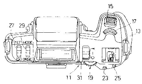
Figures 1 and 3 are a plan view and a front
elevational view of a single lens reflex camera body having
l0 an exposure control apparatus according to the present
invention, respectively. Figure 2 is a back view of a DX
code reading portion of the camera body shown in Figs. 1
and 3.
The camera body 11 has a grip portion 13 which is
i5 provided, on a front end (i.e., t:he object side) of an
upper surface thereof, with a shutter button 15. A Tv
electronic dial 17 and an Av electronic dial 19 are
provided behind the shutter button 15 and on an upper end
of the back surface of the grip portion 13, respectively.
Both the Tv electronic dial 17 and the Av electronic dial
19 are in the form of rotary dials which will be discussed
below in detail. When the Tv electronic dial 17 and the Av
electronic dial 19 are rotated, the shutter speed Tv, the
diaphragm value Av and the exposure mode can be changed. '
25 The Tv electronic dial 17 and the Av electronic dial 19
1 0
constitute part of first and second manual setting means or
first and second shutter speed and diaphragm value manual
setting means, respectively.
A clear button 23 is provided on the upper portion of
s the back surface of the camera body 11 in the vicinity of
the Av electronic dial 19. A hold button 25 is provided on
the right side of the clear button 23. 'fhe clear button 23
constitutes a part of a clear switch means.
The electronic dials 17 and 19, the clear button 23,
i0 and the hold button 25 are arranged so that when a
photographer holds the camera body 11 in a normal posture,
they can be actuated by his or her thumb or forefinger
without having to shift the camera body 11.
A slidable exposure correction/ISO lever 27 and a
15 slidable exposure mode/drive lever 29, both being slidable
in opposite directions from a neutral position are located
on the top surface of the camera body 11 to the left of a
pentagonal prism. A main switch 31 is located on the top
surface of the camera body 11 to the right of the
20 pentagonal prism and can be moved to three different
positions in a slidable manner.
DX pins DX1 ~-DX6 are provided in a patrone receiving
chamber 33 of the camera body 11 and come into contact with
DX codes, which are printed on the surface of a patrone of
25 film, to thereby read the data. In particular, the DX pins
1 1
~~~5~~~.~
DX1 ---DX6 are brought into contact with the portion of the
DX codes which represents the ISO sensitivity Sv, so as to
read the data thereof.
A group of mount pins (CONT, RES/Fmin3, SI/Fmin2,
Fmaxl, A/M, Fmax2, and -SCK /Fminl) are provided on a
body mount 35 of the camera body 11 to effect, for example,
data communication between the camera body 11 and a taking
lens. When the body mount 35 is attached to a lens mount of
the taking lens, the mount pins of the body mount 35 are
io electrically connected to the corresponding mount pins of
the taking lens, so that the camera body 11 can read lens
data, including a minimum F number Fmin (open F number) and
a maximum F number, from the taking lens and perform data
communication with a control means (ROM or CPU). The
control means (ROM or CPU) is provided in the taking lens
to read additional lens data, such as focal length data f,
or data representing the kind of taking lens attached,
etc. Note that a mark or a symbol, etc. , with an affix "-"
and a suffix "--" (e. g., -SCK , as mentioned above)
represent an active low or an inverted value in this
specification.
Figure 4 shows a circuit arrangement of a control
unit of a camera system according to the present invention.
'Phe camera body 11 has CPU 41 and IPU 43 as a control
2s means. The CPU 41 performs the fundamental photographic
1 2
calculations and control functions, such as the calculation
and determination of the exposure factors (i.e., diaphragm
value Av and shutter speed Tv), exposure control,
calculation of data necessary for automatic focus control,
etc. The CPU 41 also functions as a means for compulsively
changing the mode, returning an exposure mode, changing a
priority exposure factor, compulsively changing an exposure
mode within a specific exposure mode, setting a limit value,
holding an exposure value, manual shifting, and switching a
to set mode.
The IPU 43 functions as an input interface of the
switches, such as the shutter button 15, the Tv electron:ic
dial 17, the Av electronic dial 19, etc. The IPU 43 also
functions as an exposure mode setting means, a means for
15 controlling the indicators, a regulator for making the
power source of the CPU 41 ON and OFF (power holding), and
memory means for storing the set data and shutter speed Tv,
etc. The IPU 43 has a ROM 43a which stores programs for
determining the input of the switch data, indication of the
2o modes, communication with the CPU 41, communication with
the taking lens, etc. The IPU 43 also has a RAM 43b which
temporarily stores the set modes, the shutter speed Tv, and
the diaphragm value, etc. The IPU 43 further has an EZ PROM
(EZPROM) 43c which holds the number of film, the ISO
25 sensitivity, etc., even after the camera power source is
1 3
turned OFF.
The TPU 43 communicates with the taking lens 65 and
receives lens data, such as a maximum F number Fmax, the
minimum F number Fmin and the focal length f, etc. The IPU
43 communicates with the CPU 41 to transmit and receive the
data therebetween to control the photographic operation and
the indication of the data.
The output of a light receiving element 45 is
logarithmically compressed by an operation amplifier 47 and
to a diode D1, amplified by an amplifier 49, converted to a
digital value (Bv, BV) corresponding to an apex value by an
A/D converter 51, and input to the CPU 41 through input
ports P30 ~- P37.
The A/D converter 51 operates at a predetermined time
~5 to input the level signals of the: ports P30 -r P37 to the
C.PU 41 which reads object brightness signals and diaphragm
value signals set by the taking :lens 65 and converts the
signals to corresponding apex values. The port P40 is an
input switching control port which switches the
20 logarithmically compressed voltages amplified by the
amplifier 49 and the diaphragm voltages set by the
diaphragm volume 53. The diaphragm volume 53 generates
diaphragm voltage which corresponds to the value set by the
photographer when rotating the diaphragm ring of a taking
z5 lens (not shown) in the manual mode.
1 4
The ports P10 ~-P14 of the CPU 41 are connected to
the DX pins DX2 ~-DX6. TYze CPU 41 checks the levels of
these ports P10 ~- P14 at a predetermined time to read the
ISO sensitivity Sv. The CPU 41 then stores the input data
including the diaphragm value Av, the object brightness Bv
and the ISO sensitivity Sv, etc., in the RAM 41b at
predetermined addresses.
A winding motor 55 winds and rewinds the film, and a
mirror motor 57 moves a mirror up and down. The operations
to of the motors 55 and 57 are controlled by the CPU 41
through a motor drive circuit 59.
A release magnet RL releases the mechanical
engagement of the shutter to begin the release operation. A
shutter mechanism (shutter curtain) thus released from the
mechanical engagement by the release magnet RL is
disengageably engaged by a leading curtain magnet ES1 and a
trailing curtain magnet ES2, so that the movement of the
shutter curtain is controlled thereby. A diaphragm magnet
EE stops the stop-down operation of the the taking lens
diaphragm. The operations of these magnets are controlled
by the CPU 41 through a magnet drive circuit 61.
An EE pulse counter 63 generates EE pulses in
association with the stop-down operation, which is in turn
associated with the up-down movement of the mirror,
subsequent to the shutter release and sends the outputs
J
thereof to the port PDD of the CPU 41. The CPU 41 counts
the level change of the port PDD and when the counted
number reaches a value corresponding to the set diaphragm
value Av, the diaphragm magnet EE is turned ON through the
magnet drive circuit 61 to stop the stop-down operation
thereby maintaining the diaphragm value Av.
The parts PLO- PL6 of the CPU 43 are connected to the
mount pins (A/M, CONT, RES/Fmin3, SI/Fmin2, Fmaxl, Fmax2,
SCK /Fminl) thereby completing an electrical connection
to to 'the takizig lens 65 (i.e., memory or control means
thereof). The IPU 43 communicates with the taking lens 65
through the ports PLO ~ PL6 to read the lens data including
the open F number Fmin, the maximum F number Fmax, the
focal length f, etc.
The taking lens 65 has a lens auto/manual selection
switch 67 which switches between a manual diaphragm mode
(lens-manual mode) and an automatic diaphragm mode
(lens-auto mode) in association with a diaphragm ring 12.
The lens auto/manual selection switch 67 is connected to an
z~ input port PLO of the IPU 43 through the mount pin A/M. The
TPU 43 determines the existence of the manual diaphragm
mode or the automatic diaphragm mode in accordance with the
level of the port PLO. The "lens-auto mode" mentioned above
is an automatic diaphragm mode in which the stop-down
z5 mechanism of the camera continues the stop-down operation
1 6
until the diaphragm value becomes a predetermined value
which has been set in the camera body. The "lens manual
mode" mentioned above is a manual diaphragm mode in which
the diaphragm value is manually set on the taking lens
side. The lens-auto mode will also be referred to as a
"body set'° hereinafter.
Input ports PCO -~- PC2 and PBO ~- PB5 of the IPH 43 are
connected to a main switch SWMAIN, a photometer switch SWS,
a release switch SWR, an exposure mode switch SWMODE, a
1o drive switch SWDRIVE, an exposure correcting switch SW~ EF,
an ISO sensitivity setting switch SWISO, a clear switch
SWCL and a hold switch SWHOLD, respectively.
The main switch SWMAIN is associated with a main
switch lever 31. The photometer switch SWS and the release
switch SWR are associated with the shutter button 15. The
switch SWS remains open until the shutter button 15 is
depressed by a half step at which point it is turned ON.
The switch SWR is turned ON when the shutter button 15 is
depressed by full step. The exposure mode switch SWMODE and
2o the drive switch SWDRIVE are associated with the exposure
mode/drive lever 29. The exposure correcting switch SW~ EF'
and the ISO sensitivity setting switch SWTSO are associated
with the exposure/ISO lever 27. The clear switch SWCL and
the hold switch SWHOLD remain open until their respective
associated buttons, clear button 23 and hold button 25, are
1 7
effected.
The IPU 43 detects the ON/OFF state of the switches
SW, mentioned above, in accordance with the input levels of
the input ports PC and PB of the IPU 43 to perform the
necessary operations.
A pair of input ports PAO and PA1 and another pair of
input ports PA2 and PA3 of the IPU 43 are connected to the
TV electronic dial 17 and the Av electronic dial 19,
respectively. Each of the TV electronic dial 17 a.nd the Av
electronic dial 19 has a click-stop rotation mechanism per
se known. For example, a pair of input ports PAU and PAl
are in a floating state at a click-stop position, when the
electronic dials 17 and 19 are rotated in a clockwise or
counterclockwise direction, the level of one of the input
ports first drops to "L" and then the level of the other
drops to level "L", in accordance with the direction of the
rotation of the dials. Thereafter, the one input port, the
level of which has dropped to level "L" prior to the other,
is returned to the floating state prior to the other. Since
the order of change in the level of the input ports PAO and
PA1 or PA2 and PA3 depends on the rotation of the dials,
the IPU 43 can discriminate the direction of rotation based
on the order of change.
A group of ports PLCD of the IPU 43 are connected to
an LCD display panel 69 and an indicator 71. The indicator
1 8
71 is located in the finder. The LCD panel 69 is
controlled by the IPU 43 to indicate various photographic
information, such as the exposure mode, the shutter speed
Tv, the diaphragm value Av, the number of remaining frames
in a roll of film, the drive mode and other data (i.e., ISO
sensitivity data, and exposure correcting data~ EF, etc.).
The indicator 71 within the finder has indicating elements
71a and 71b which indicate the shutter speed Tv, the
diaphragm value Av, and an under-exposure, over-exposure
to or optimum exposure of the film. The indicator 71 also has
an indicating element 71c which indicates whether or not
the memory is locked.
The main circuit structure of the camera system
according to the present invention, as discussed above,
i5 operates as follows. Note that the values of the shutter
speed '.I'v, the diaphragm value Av, and the object brightness
Bv in the arithmetic operation discussed below are all
those used in calculating the APEX values.
25
1 9
~~~~9~~
Main Operation of CPU
The main operation of the CPU 41 will be discussed
below with reference to the flow chart shown in Fig. 5. The
main operation is carried out in accordance with the
program stored in the ROM 41a of the CPU 41.
When the photometer switch SWS is turned ON after the
main switch SWMAIN is turned ON, electrical power is
supplied to the CPU 41 and the operation shown in the flow
chart of Fig. 5 is performed.
to The CPU 41 first initializes all the input ports P at
step 511, anc9 then initializes the RAM 41b at step 512.
Thereafter, the DX code (ISO sensitivity SV), the object
brightness Bv, and the diaphragm value Av set by the
diaphragm volume 53 when in the LM mode, are input to the
i5 CPU (steps S13, S14 and S15).
Thereafter, the CPU 41 communicates with the IPU 43
to receive the necessary data, such as the set photographic
exposure mode and the exposure factors, etc., from the IPU
43 (step S16).
20 The control proceeds to step S18 in which the
exposure calculation is effected to obtain optimum exposure
factors in accordance with the selected photographic
exposure mode, the calculation being based on the ISO
sensitivity Sv and the object brightness Bv, etc.
25 Thereafter, the CPU 41 performs data communication with the
2 0
20~~~~
IPU 43 to send the calculated exposure factors (i.e.,
shutter speed Tv and diaphragm value Av) to the IPU 43
(step S19).
After the exposure factors are determined, the
control proceeds to step S20 where it is determined whether
or not the release switch SWR is turned ON. I.f the release
switch SWR is turned ON, the releasing operation is
effected (step S21). If the release switch SWR is turned
OFF, the control is returned to step 513. While the power
1o is held (i.e., while the power continues to be supplied),
the operations of step S13 to step S20 are repeated.
Data Communication with IPU
The CPU 41 performs data communication with the IPU
43. The data communication will be explained below with
reference to F'ig. 6 and Table 1 (at:tached to the last page
of the specification). Each of the CPU 41 and IPU 43 has
terminals corresponding to CE, READY, -SCK-, and DATA which
are connected to each other.
2o The CPU 41 raises the level of the terminal CE (not
shown), so that IPU 43 is ready for communication. When the
IPU 43 monitors the level of the terminal CE which is
changed from "L" to "H" , the level of the terminal READY is
dropped and then raised, so that interruption by the CPU 41
is permitted.
2 1
When the CPU 41 monitors 'the permission to interrupt,
a clock signal is output to the terminal -SCK (not shown),
and a command is output to the terminal DATA. Upon
completion of receipt of the command, the IPU 43 drops and
then raises the level of the terminal READY, so that the
CPU 41 detects the completion of the receipt. The IPU 43
outputs data corresponding to the received command in
accordance with the clock signal sent from the terminal
SCK of the CPU 41, or receives data from the CPU 41.
to When the communication of the necessary data is
completed, the IPU 43 drops the level of the terminal
READY. Thereafter, the CPU 41 drops the level o.f the
terminal CE, so that the IFU 43 detects that the data
communication with the CPU is completed. When the IPU 43
i5 monitors the level drop of the germinal CE, the IPU 43
raises the level of the terminal READY to finish the data
communication.
AE Sub-routine
The sub-routine for calculating the exposure
(automatic exposure mode) at step S18 will be discussed
below with reference to the flow chart shown in Fig. 7.
In this AE process, the DX codes representing the ISO
sensitivity are converted to APEX values (film sensitivity
25 Sv) at step 550. The DX codes of the ISO sensitivity
2 2
consist of 5 bit signals and are read by the five DX pins
(5 bits) DX4, DX3, DX2, DX5 and DX6 which come into contact
with the codes in the illustrated embodiment. The upper
three bits (DX4, DX3 and DX2) constitute an integer and the
lower two bits (DX5 and DX6) a decimal. For example, if the
decimal is "O1" or "11", the APEX value is 0/3, if the
decimal is "10", the APEX value is 1/3, and if the decimal
is "00", the APEX value is 2/3. The decimal thus converted
to the APEX value is added to the integer. For example, the
DX code of :LSO 100 is represented by Sv=5, since the
integer "101" is converted to an APEX value "5" and the
decimal "O1" is converted to an APEX value "0".
Thereafter, the object brightness Bv is converted to
a calculating object brightness BVD suitable for
calculation by using the following equation: BVD=Bv + 7,
(step S51). Thereafter, the film sensitivity Sv and the
exposure correcting value Xv are converted to a calculating
sensitivity SVD and a calculating exposure correcting value
XVD suitable for calculation by using the following
2U equations, respectively (step S52):
SVD=Sv- 1; XVD=4- Xv
The above-mentioned operations are effected not only
to prevent the values of the calculating exposure factors
BVD, SVD, XVD from being negative, but also to unify the
accuracy or precision of the exposure factors to be a 1/8Ev
2 3
step. Consequently, the APEX calculation (i.e., addition
and subtraction) can be easily effected without considering
the calculation accuracy. Note that since the precision of
Sv and Xv is within 1/3 Ev, it is in theory impossible to
convert them to values of a 1/8Ev step. To this end, Sv and
Xv are rounded to approximately 1/3Ev and 2/3Ev to 3/8Ev
and 5/BEv, respectively.
Thereafter, the brightness correction value MND
depending on a change of the open F number, is calculated
1o at step 553. The brightness correction value MND is adapted
to correct the object brightness Bv so as to maintain the
exposure on a film plane at a constant value, regardless
of, for examp:Le, a change in the open F number (i.e.,
change in brightness of the lens) during zooming and is a
value peculiar to the taking lens. The brightness
correction value MND is input from the taking lens by
communication of the IPU 43 with the taking lens (IPU-lens
communication), which will be discussed hereinafter, and is
transferred from the IPU 43 to the CPU 41 through the
2o CPU-1PU communication at step 516.
Thereafter, the calculating exposure value LVD is
calculated, based on the calculating object brightness BVD,
the calculating sensitivity SVD, the calculating exposure
correcting value XVD, and the brightness correcting value
MND by using the following formula;
2 4
~p~~~~4
~VD=BVD + SVD + XVD + MND
The CPU ~~l detects the selected exposure mode and
calls the exposure factor calculating sub-routine
corresponding to the selected exposure mode (steps S55-1-~-.
S55-n, S56-1-~-S56-n). The diaphragm value Av and the
shutter speed Tv are then calculated in accordance with the
algorithm of the selected exposure mode. Thereafter, the
control is returned. If an incorrect exposure mode is set,
an error operation as described below is carried out (step
to S57).
Error Operation
In the error operation at step 557, the calculating
shutter speed TVD and the calculating diaphragm value AVD
are replaced with a calculating maximum shutter speed
TVDMAX and a calculating maximum diaphragm value AVDMAX,
respectively, and the number PN (or Pno) of EE pulses is
set at the maximum value, i.e., 225. Thereafter, the
calculating shutter speed TVD (the calculating maximum
2o shutter speed TVDMAX ) and the calculating diaphragm value
AVD (i.e., the calculating maximum diaphragm value AVDMAX)
are converted to values suitable for transmission to the
IPU in processes labeled TVDT (TVD~ 'PVT) and AVDT (AVD-~
AVT), as explained in detail hereinafter (see Fig. 8).
Thereafter, the control is returned.
2 5
It is possible to replace one or both of the
calculating shutter speed TVD and the calculating diaphragm
value AVD with a calculating minimum shutter speed TVDMIN
and a calculating minimum diaphragm value AVDMIN, in place
of the calculating maximum shutter speed TVDMAX and the
calculating maximum diaphragm value AVDMAX, respectively.
Exposure Calculating Sub-routine
In the illustrated embodiment, the exposure modes
to include a program automatic exposure mode in which the
shutter speed and the diaphragm value are automatically set
in accordance with the object brightness, a shutter speed
priority (EE LA) automatic exposure mode (lens-auto mode)
in which the diaphragm value is automatically set in
accordance with the manually set shutter speed and object
brightness, a diaphragm priority (ES LA) automatic exposure
mode in which the shutter speed is automatically set in
accordance with the manually set diaphragm value and object
brightness, a manual exposure (Manual LA) and bulb
2o exposure (Bulb LA) modes, and a diaphragm priority (ES LA)
automatic exposure mode (lens-manual mode).
Furthermore, in the illustrated embodiment, there is
a limited program (Program LIMT) automatic exposure mode, a
hyper-program (Hyper Program) automatic exposure mode used
25 as a specific program exposure mode, a hyper shutter
2 E~
2~0~~9~~
priority (Hyper EE) automatic exposure mode (lens-auto
mode), and a hyper diaphragm priority (Hyper ES) automatic
exposure mode.
The following discussion will be directed to an
exposure factor calculation process in the above-mentioned
exposure modes with reference to Figs. 9 through 23.
Hyper Program
The hyper program exposure mode referred to herein is
a mode in which the program mode, the EE automatic exposure
mode and the ES automatic exposure mode are changed by
optionally selecting the hyper program exposure mode, the
hyper EE automatic exposure mode, or the hyper ES automatic
exposure mode. Operations of Hyper-program mode are
s5 identical to those of the ordinary program mode, except
that the exposure mode can be varied between the above
three modes by actuating the electronic dials 17,19 or the
clear button 23.
Figure 9 shows a flow chart involving the hyper
program exposure mode and the ordinary program exposure
mode and Fig. 10 shows a program diagram thereof.
First, the relationship between the calculating TVD
corresponding to the Tv value and the calculating AVD
corresponding to the Av value is obtained by the following
formula, in accordance with the formula at step 554.
2 7
LVD=BVD+ SVD + XVD -E- MND
(Bv+ 7)+ (Sv - 1)+ (4- Xv) -I- MND
_ ( Bv-F Sv- Xv+ MND ) + 10
=Ev + 10
=Tv + Av+ 10
=(Tv+ 5 4/8)+ (Av + 4 4/8)
=TVD+ AVD
Here,
Ev=Bv -I- Sv- Xv+ MND
TVD=Tv + 5 4/8 ...(1)
AVD=Av + 4 4/8 ...(2)
From the equations (1) and (2), the relationships
between Tv and TVD and between Av and AVD are obtained, The
respective constants added to Tv and Av in equations (1)
i5 and (2) are not limited to 5 4/8 and 4 4/8 and can be any
two values whose sum is 10. The values of 5 4/8 and 4 4/8
are selected to be approximate to each other in the
embodiment. Correspondences between Tv and TVD and between
Av and AVD thus obtained are shown in Table 2 and Table 3
20 (attached to the last page of the specification), by way of
example:
In the program exposure mode, the optimum calculating
shutter speed TVD is obtained by the following equation:
TVD=3/8 LVD + 4 6/8
25 The calculating exposure value LVD is obtained at
2 8
step 554. Consequently, the optimum calculating diaphragm
value AVD is obtained from the result of this calculation
( steps S61-v S?8 ) .
The equation mentioned above is obtained from the
basic formula of the program line (Tv=3/8 Ev-;- 3) in which
TVD=Tv+ 5 4/8 and AVD=Av+ 4 4/$. When the optimum
calculating shutter speed TVD and the optimum calculating
diaphragm value are within the shutter capability range of
the camera body 11 (range between the calculating maximum
to shutter speed TVDMAX and the calculating minimum shutter
speed TVDMIN) and the diaphragm capability range of the
taking lens (range between the calculating maximum
diaphragm value AVDMAX and the calculating minimum
diaphragm value AVDMIN), the optimum calculating shutter
speed and 'the optimum calculating diaphragm value are
maintained, and the EE pulse number PN, used to maintain
the diaphragm value Av of the diaphragm of the taking lens
during the releasing operation, is calculated (steps S62,
S64 -~-566, 568, 569, S72). The maximum shutter speed TVDMAX
2o and the minimum diaphragm value AVDMIN referred to are the
maximum shutter speed and the open F number, respectively.
The maximum and minimum shutter speeds TVDMAX and
TVDMIN are peculiar to. the camera body 11 and are TVDMAX
=13 (1/8000 sec.) and TVDMIN -- 5 (30 sec.) in the
illustrated embodiment, respectively. Consequently, as
2 9
TVD=TV+ 5 4/8, the calculating maximum and minimum shutter
speed TVDMAX and TVDMIN are represented respectively by;
TVDMAX =TVMAX + 5 4/8=18 4/8
TVDMIN =TVMIN + 5 4/8=0 4/8
The calculating maximum and minimum shutter speed
TVDMAX and TVDMIN are stored in advance in the internal ROM
41a of the CPU 41 and are memorized at predetermined
addresses of the RAM 41b during the operations.
Using the inherent maximum and minimum diaphragm
1o values AVMAX and AVMIN and the formula (AVD=AV+ 4 4/8), the
calculating maximum and minimum diaphragm values AVDMAX and
AVDMIN are represented respectively by;
AVDMAX =AVMAX + 4 4/8
AVDbIIN =AVMIN + 4 4/8
The maximum and minimum diaphragm values AVMAX and
AVbIIN are input by the communication with the taking lens
at step S35 and the calculating maximum and minimum
diaphragm values AVDMAX and AVDMIN are stored in the
internal RAM 41b of the CPU 41 at predetermined addresses
2o thereof.
If the object is too bright or dark to calculate the
optimum exposure factors using the above-mentioned program
line, the following operations are carried out.
When the object is too bright:
Tf the calculating shutter speed TVD is larger than
3 0
the calculating maximum shutter speed TVDMAX, the optimum
calculating diaphragm value AVD is calculated after the
calculating shutter speed TVD is replaced with the
calculating maximum shutter speed TVDMAX (steps S62 ~-S64).
If the optimum calculating diaphragm value AVD thus
obtained is within the diaphragm capability range, the EE
pulse number PN is obtained in accordance therewith (steps
565, 566, S68 and S72).
If the optimum calculating diaphragm value AVD ~.s
to larger than the calculating maximum diaphragm value AVDbiAX,
the optimum calculating shutter speed TVD is recalculated
after the optimum calculating diaphragm value AVD is
replaced with the calculating maximum diaphragm value
AVDMAX (steps S65 -v S68). zf the recalculated calculating
shutter speed TVD is larger than the calculating
maximum shutter speed TVDMAX, it is out of the range in
which optimum exposure can be obtained by any combination
of the calculating shutter speed TVD and the calculating
diaphragm value AVD. Consequently, an Ev out-of association
2o bit is set at "1" to indicate that the calculating shutter
speed is out of association (i.e., the allowable range), and
the calculating shutter speed 'PVD is then replaced with the
calculating maximum shutter speed TVDMAX to calculate the
EE pulse number PN (steps S69 ~ S72). If the recalculated
calculating shutter speed TVD is within the shutter
:> 1
5
capability range, since optimum exposure can be effected,
the control skips steps S70 and S71 and performs the
calculation of the EE pulse number PN in accordance with
the optimum calculating diaphragm value AVD (steps S69 and
72).
When the EV out-of association bit is set at "1", the
shutter speed (maximum shutter speed TVMAX) and the
diaphragm (maximum diaphragm value AVMAX) is indicated in
the LCD display panel 69 in a flickering manner.
to When the object is too dark:
If the optimum calculating diaphragm value AVD is
smaller than the calculating minimum diaphragm value
AVDMIN, the optimum calculating shutter speed TVD is
recalculated after the calculating diaphragm value AVD is
=~5 replaced with the calculating minimum diaphragm value
AVDMIN. If the recalculated calculating shutter speed TVD
is within the shutter capability range, the value is
held and the EE pulse number PN is set at 0, as the
diaphragm is an open F number (steps S73-~-575, S78).
2o If the optimum calculating shutter speed TVD is
smaller than the calculating minimum shutter speed TVDMIN,
under-exposure conditions exist, and accordingly, the Ev
out-of association bit is set at "1" and the calculating
shutter speed TVD is replaced with the calculating minimum
25 shutter speed TVDMIN. Thereafter, the EE pulse number PN
3 2
~~~a98~
is set at 0 (steps S75-~-S78). TVD and AVD are stored at
predetermined addresses of the RAM 41b and are utilized to
control the shutter speed anrl r~i ar~hrarrm vW "o ,.,r,o.,
releasing.
When the above-mentioned operations are completed,
the calculating diaphragm value AVD and the calculating
shutter speed TVD are replaced with a transferring
diaphragm value AVT and a transferring shutter speed TVT,
respectively (steps S79 and S80). The relationships between
l0 the calculating diaphragm value AVD and the transferring
diaphragm value AVT and between the calculating shutter
speed TVD and the transferring shutter speed TVT are as
follows.
TVT-TVD+ 10 4/8
AVT=AVD
Although TVT and AVT are not rounded in the above
equations, TVT and AVT are rounded in the actual operation.
The transferring shutter speed TVT and the
transferring diaphragm value AVT are data of a 1/2Ev step.
Namely, when this data is transferred from the CPU 41 to
IPU 43, the calculated values of a 1/8Ev step are rounded
to 1/2Ev. This is because the data is used only to indicate
the necessary information in the IPU 43, so that accuracy
greater than a 1/2Ev step is unnecessary. Tables 2 and 3
mentioned above show indicating sections corresponding to
3 3
2~0~~~4
the values of TVD and AVD by way of example.
Thus, the operation of the program exposure mode is
finished and the program line (diagram) shown as a solid
line in Fig. 10 is obtained.
l0
20
,'3 4
Limited Program Exposure Mode
Figure 11 shows a sub-routine of the limited program
exposure (automatic exposure) mode in which a photographer
can set the calculating minimum and maximum shutter speeds
TVD1 and TVD2 and the calculating minimum and maximum
diaphragm values AVD1 and AVD2, respectively. The
operational flow in this sub-routine is similar to that of
the sub-routine of the program exposure mode except for the
following points. Namely, in the sub-routine shown in Fig.
z0 11, the calculating minimum and maximum diaphragm values
AVDMIN and AVDMAX are replaced with the set minimum and
maximum diaphragm values AVD1 and AVD2, respectively (steps
585, 593, 586, S87), and the calculating minimum and
maximum shutter speeds TVDMIN and TVDMAX are replaced with
i5 the set minimum and maximum shutter speeds TVD1 and TVD2,
respectively (steps 595, 597, S82,S83, 589, S91). The
program diagram of the limited program exposure mode is
shown in Fig. 12.
The calculating minimum and maximum diaphragm values
20 AVDMIN and AVDMAX, and the calculating minimum and maximum
shutter speeds TVDMIN and TVDMAX are set by actuating the
hold button 25 and rotating the Tv electronic dial 17 and
the Av electronic dial 19 when the limited program exposure
mode has been selected. The setting operation shown in the
'~ flow chart of Figs. 39C and 39D will be discussed in
3 5
detail hereinafter.
Hyper-EE Automatic Exposure Mode
Figure 13 shows a flow chart of the hyper-shutter
priority (Hyper-EE) automatic exposure mode. The program
diagram thereof is shown as a dotted-dashed line in Fig. 10.
The operation for calculating the exposure factors
at the hyper-shutter priority automatic exposure mode is
basically the same as the operation of the ordinary shutter
to priority automatic exposure mode (lens-auto mode), except that
the exposure mode can be changed by actuating the
electronic dials 17, 19 or the clear button 23.
The hyper-EE automatic exposure mode is an EE
automatic exposure mode which is compulsively selected when
i5 'the hyper program exposure mode is selected and when the Tv
electronic dial 17 has been actuated. Return from the
hyper-EE automatic exposure mode to the hyper-program
exposure mode is effected by the operation of the clear
button 23 or the power switch, etc. The switch from the
2o hyper-EE automatic exposure mode to the hyper-ES exposure
mode is compulsively effected by the rotation of the Av
electronic dial 19.
In the hyper-EE automatic exposure mode, the set
shutter speed TVT transferred from the IPU 43 by the data
25 communication is read and converted to the calculating
6
shutter speed TVD (step 5101). The relationship between the
transferring shutter speed TVT and the calculating shutter
speed TVD is as follows.
TVD=TVT- 10 4/$
The transferring shutter speed TVT, which is 1/2 Tv
in step, is converted to the calculating shutter speed TVD,
which is 1/8 Tv in step, by the above operation.
The transferring shutter speed TVT is represented by
data of a 1/2Ev step and is processed upon calculating, so
io that the decimal place thereof is identical to that of the
calculating shutter speed TVD (i.e., data which is 1/8Ev in
step). Accordingly, the Tv value, which is set by the user
(i.e., TVT) set as the calculating shutter speed TVD in
predetermined addresses of RAM 41b.
Thereafter, the optimum calculating diaphraam value
AVD is calculated using the calculating shutter speed TVD
and the calculating exposure value LVD (step 5102).
If the optimum calculating shutter speed AVD is
within the diaphragm capability range, the values are held
2o and the EE pulse number is calculated (steps S103, 5104,
S 10 8-~- S 110 ) .
If the optimum calculating diaphragm value AVD is out
of the diaphragm capability range, namely, if the object is
too bright or dark, the following operations are performed.
When the object is too bright:
J 7
If the optimum calculating diaphragm value AVD is
greater than the calculating maximum diaphragm value AVDMAX,
the calculating diaphragm value AVD is replaced with the
calculating maximum diaphragm value AVDMAX. This
replacement causes an over-exposure condition, and
accordingly, the EE pulse number PN is set after the Av out-
of-association bit signal is set at "1" to indicate that
the optimum calculating diaphragm value AVD is ou-t of
association (steps S103, 5106 -~-5110). When the Av
out-of-association bit signal is set, the number "22",
indicating the diaphragm value Av in the LCD display panel
69, flickers to indicate over-exposure.
When object is too dark:
If the optimum calculating diaphragm value AVD is
smaller than the calculating minimum diaphragm value
AVDMIN, the calculating diaphragm value AVD is replaced
with the calculating minimum diaphragm value AVDMIN. This
replacement causes an under-exposure condition, and
accordingly, the EE pulse number PN is set at "0" after the
Av out-of--association bit signal is set at "1" (steps 5103~-
5105, 5107, 5108, and 5110). Thus, the diagram as shown as
a dotted and dashed line in Fig. 10 is obtained.
When the setting of the EE pulse number PN is
finished, the calculating diaphragm value AVD and the
calculating shutter speed TVD are converted to the
3 g
transferring diaphragm value AV'P and the transferring
shutter speed TVT to complete the operation, respectively
(steps 5111 and 5112).
Hyper-ES Automatic Exposure Mode
An embodiment of the hyper diaphragm priority (ES)
automatic exposure mode (lens-auto mode) will be explained
below with reference to Figs. 10 and 16.
The basic operations in the hyper-ES automatic
to exposure mode is basically the same as the operation of the
conventional ES automatic exposure mode (lens-auto or
body-set mode).
The hyper-ES automatic exposure mode is an ES
automatic exposure mode which is compulsively selected when
15 the hyper program exposure mode is selected and when the Av
electronic dial 19 has been actuated. The return from the
hyper-ES automatic exposure mode to the hyper-program
exposure mode is effected by the operation of the clear
button 23 or the power switch, etc. The switch from the
20 hyper-ES automatic exposure mode to the hyper-EE exposure
mode is compulsively effected by the rotation of the Tv
electronic dial 19.
In the hyper-ES automatic exposure mode, the set
diaphragm value AVT transferred from the IPU 43 by the data
25 communication is read to convert same to the calculating
3 9
~~~~~8
diaphragm value AVD (step 5131). The transferring diaphragm
value AVT is identical to the calculating diaphragm value
AVD (i.e., AVD=AVT). Accordingly, the diaphragm value Av
manually set by the user(i.e., AVT) is set as the
s calculating diaphragm value AVD at predetermined addresses
of the RAM 41b.
The transferring diaphragm value AVT is represented
by data which is 1/2Ev in step, and it is processed upon
calculating so that the place thereof is identical to that
1o of the calculating diaphragm value AVD (i.e., data which is
1/8Ev in step).
Thereafter, the optimum calculating shutter speed TVD
is calculated using the calculating exposure value AVD and
the calculating exposure value LVD (step 5132).
l5 If the optimum calculating shutter speed TVD is
within the shutter capability range, the values are held
and the EE pulse number is calculated in accordance with
the calculating diaphragm value AVD (steps 5133, 5134, 5138 --
5140).
2o If the optimum calculating shutter speed TVD is out
of the shutter capability range, namely, if the object is
too bright or dark, the following operations are performed.
When the object is too bright:
Tf the optimum calculating shutter speed TVD is
25 greater than the calculating maximum shutter speed TVDMAX,
4 0
2~~~~~
the calculating shutter speed TVD is replaced with the
calculating maximum shutter speed TVDMAX. This replacement
causes an over-exposure condition, and accordingly, the EE
pulse number PN is set after the Tv out°of-association bit
signal is set at "1" to discriminate that the optimum
calculating shutter speed TV is out of association (steps
5133, 5136- 5140).
When the object is too dark:
If the optimum calculating shutter speed TVD is less
than the calculating minimum shutter speed TVDMIN, the
calculating shutter speed TVD is replaced with the
calculating minimum shutter speed TVDMIN. This replacement
causes an under-exposure condition, and accordingly, the EE
pulse number PN is set at "0" after the Tv out-of-association
bit signal is set at "1" (ste,ps 5133-5135, 5137, 5138-4
5140).
When the EE pulse number PN is set, the calculating
diaphragm value AVD and the calculating shutter speed TVD
are converted to the transferring diaphragm value AVT and
the transferring shutter speed TVT to complete the
calculation of the exposure factors (steps 5141 and 5142),
respectively. Thus, the diagram as shown as a dotted line
in Fig. 10 is obtained.
Second Hyper-EE or ES Automatic Exposure Mode
~l I
'the second hyper-EE or ES automatic exposure mode is
an automatic exposure mode in which the priority exposure
factor is modified only under the condition that the '
non-priority exposure factor cannot be adjusted to avoid
the occurrence of under-exposure or over-exposure. Namely,
unlike the above mentioned hyper-EE or hyper-ES automatic
exposure modes in which a change of the priority exposure
.factor (i.e., diaphragm value or shutter speed having a
priority) does not take place even if the object is too
to bright or dark, the exposure factor having a priority is
modified when the modification of the exposure factor
having no priority , cannot be adjusted to avoid
over-exposure or under-exposure.
Tn the second hyper-EE or ES automatic exposure mode,
i5 i.f the shutter speed or the diaphragm value having priority
causes under-exposure or over-exposure, the shutter speed
or the diaphragm value is modified to provide an optimum
exposure (Figs. 15 and 18).
The operations in the second hyper-EE automatic
2o exposure mode and the second hyper-ES automatic exposure
mode will be discussed below with reference to Figs. 14 and
17, respectively.
In the second hyper-EE automatic exposure mode, the
set shutter speed TVT stored in the IPA 43 is read by the
25 operation of the Tv electronic dial 17 to convert same to
4 2
the calculating shutter speed TVD, so that the optimum
calculating diaphragm value AVD is calculated in
accordance with the calculating shutter speed TVD and the
calculating exposure value LVD (steps S121 and 5122). If
the optimum calculating diaphragm value AVD is within the
diaphragm capability range, the control enters step 5132 of
the hyper-ES automatic exposure mode as can be seen in Fig.
16 ('steps S123, 5125 and 5127).
If the optimum calculating diaphragm value AVD is
to greater than the calculating maximum diaphragm value
AVDMAX (i.e., if the object is too bright), the calculating
diaphragm value AVD is replaced with the calculating
maximum diaphragm value AVDMAX, and then the control
enters step 5132. Conversely, if the optimum calculating
diaphragm value AVD is less than the calculating minimum
diaphragm value AVDMIN (i.e., if the object is too dark),
the control enters step S132 after the calculating
diaphragm value AVD is replaced with the calculating
minimum diaphragm value AVDMIN (steps 5123, 5125 5127).
2~ In step 5132 of the hyper-ES automatic exposure made
(diaphragm priority automatic exposure mode), the
calculating shutter speed TVD is recalculated to modify the
shutter speed.
Consequently, the diagrams as shown by a solid line,
a dotted line and a two-dotted and dashed line in Fig. 15
~ 3
are obtained. As can be seen in Fig. 15, the optimum
exposure range is widened. This can be considered a kind of
program automatic exposure mode in which the shutter
priority automatic exposure mode functions in a certain
exposure range.
In the second hyper-ES automatic exposure mode, the
set diaphragm value AVT stored in the IPU 43 is read by the
operation of the Av electro.nic dial 17 to convert the same
to the calculating diaphragm value AVD, so that the optimum
calculating shutter speed TVD is calculated in accordance
with the calculating diaphragm value AVD and the
calculating exposure value LVD (steps 5151 and 5152). If
the optimum calculating shutter speed TVD is within the
shutter capability range, the values are held and the
15 control enters step 5102 of the hyper-EE automatic exposure
mode in Fig. 13 (steps 5153, 5155 and 5157).
If the optimum calculating shutter speed TVD is
greater than the calculating maximum shutter speed TVDMAX
(i.e., if the object is too bright), the calculating
20 shutter speed TVD is replaced with the calculating maximum
shutter speed TVDMAX, and then, the control enters step
S102 of the shutter priority automatic exposure mode.
Conversely, if the optimum calculating shutter speed
TVD is less than the calculating minimum shutter speed
2s TVDMIN (i.e., if the object is too dark), the control
L1
enters step 5102 after the calculating shutter speed TVD
is replaced with the calculating minimum shutter speed
TVDMIN. In step S1U2, the calculating diaphragm value AVD
is recalculated to modify the diaphragm value (steps 5103 -~
5112).
Consequently, the diagrams as shown by a solid line,
a dotted line and a two-dotted and dashed line in Fig. 18
are obtained. As can be seen in Fig. 18, the optimum
exposure range is extended. This can be considered a kind
to of program automatic exposure mode in which the diaphragm
priority automatic exposure mode functions in a certain
exposure range.
Although the first and second hyper EE automatic
exposure modes and the first and second hyper ES automatic
exposure modes are separately explained, the operations of
these modes can be performed in the same camera. Namely, 2
bit signals of the exposure mode data of the EZPROM 43c
included in the IPIJ 43 correspond to those of the
above-mentioned first and second methods in the hyper-EE
2o and hyper-ES automatic exposure modes, respectively. The
signal data is transferred to the CPU 41 by the CPU-IPU
communication, so that the 2 bit signals can be determined,
after the hyper-EE mode or the hyper-ES mode is detected,
to switch the first or second hyper-EE and hyper-ES modes.
4 5
LA Hyper-Manual Exposure Mode
The hyper-manual exposure mode (body set mode) in
which both the shutter speed and the diaphragm value can be
manually set by the operation from the camera body side
s will be discussed below with reference to Fig. 19.
In the hyper-manual exposure mode (lens-auto or body
set mode), a photographer can set the exposure factors by
actuating the electronic dials 17 and 19. However, when the
clear button 23 is turned ON, the optimum exposure factors
1o are automatically calculated in accordance with the object
brightness I~v, based on the algorithm identical to that of
the prograrn exposure mode. When the clear button 23 is
turned OFF, the calculated exposure factors a.re replaced
with those which are manually set.
15 In the LA hyper-manual exposure mode, both the
shutter speed Tv and the diaphragm value Av can be set when
the Tv and Av electronic dials 17 and 19 are actuated,
respectively. Furthermore, when 'the clear button 23 is
turned ON, the function equivalent to the program automatic
2o exposure mode can be performed. The set shutter speed Tv
and diaphragm value Av are stored in the IZAM 43b of the IPU
43 at predetermined addresses thereof and are indicated in
the LCU panel 69 and the indicator unit 71 within the
finder.
25 While the clear button 23 is turned ON, the
4 6
calculating shutter speed TVD and the calculating diaphragm
value AVD are calculated in accordance with the program
exposure mode and the control then proceeds to step 5167
(step 5164).
If the clear button 23 is not turned ON, the set
diaphragm value AVT and the set shutter speed TVT,
transferred from the IPU 43, are converted to the
calculating diaphragm value AVD and the calculating shutter
speed TVD, and the control then proceeds to step 5167
(steps s161 ~-5163).
At step 5167, an exposure error p Ev is calculated by
the following equation which is based on the optimum
calculating exposure value LVD, obtained from the result of
the actual photometering, and the exposure value (AVD -~-
15 TVD), which is obtained by the calculating diaphragm value
AVD, identical to the set calculating diaphragm value, and
the calculating shutter sgeed TVD, identical to the set
calculating shutter speed:
4 Ev=LVD-~ ( AVD-h TVD )
2o If the exposure error p Ev is within an allowable
limit ( - 3/8 < p Ev< + 3/8), overexposure and
underexposure indication bits are set to illuminate a pair
of LED exposure indicating elements 71a and 71b (Fig. 42E)
in the indicator unit 71 within the finder (steps 5168,
25 5170, S171).
L
If the exposure error p Ev is greater than the
allowable upper limit, only the overexposure indication bit
is set to illuminate the indicating element 71a to thereby
indicate over-exposure (steps 5168 and 5169). Conversely,
if the exposure error p Ev is less than the allowable lower
limit, only the underexposure indication bit is set to
illuminate the indicating element 71b to thereby indicate
under--exposure (steps 5168, 5170 and 5172). Although
the allowable limit of exposure error p Ev is ~ 3/8Ev in
lp the illustrated embodiment, another limit may be selected.
Furthermore, the upper limit value and the lower limit
value can be different from each other. It is also possible
to read the latitude of the loaded film from the DX code,
so that the allowable limit is determined to be identical
to that of the film latitude.
'thereafter, the number PN of EE pulses is obtained
from the calculating diaphragm value AVD (steps 5173, 5174
and 5175), and the calculating diaphragm value AVD and the
calculating shutter speed TVD are converted to the
transferring diaphragm value AVT and the transferring
shutter speed TVT, respectively.
When the clear button is turned OFF after being ON,
the optimum exposure value in the program exposure mode is
converted to the series value at steps S162 and 5163, which
will be discussed hereinafter, and is stored at
4 8
predetermined addresses of the RAM 41b with the accuracy
equivalent to that of the manual mode.
As can be understood from the foregoing, since, when
the clear button 23 is turned ON in the hyper-manual
exposure mode, both the shutter speed Tv and the diaphragm
value Av are modified to optimum values depending on the
photometering data (object brightness Bv) in accordance
with the program exposure mode, the optimum exposure value
can be manually and quickly set by a simple operation.
1o Although the calculation of the optimum exposure factors
continues while the clear button 23 is turned ON in the
above mentioned embodiment, it is possible to calculate the
exposure factors and store the same in the RAM 41b only
when the clear button 23 is switched from OFF to ON. In
this alternative, at step S161, whether the clear button 23
is switched from OFF to ON is checked.
2.0
d 9
Second L~A Hyper-manual Exposure Mode
In the above mentioned embodiment, the diaphragm
value Av and the shutter speed Tv are modified to these
detected by the photometering operation, in accordance with
s the program automatic exposure mode, when the clear button
23 is turned ON. It is possible to modify only one of the
exposure factors Av and Tv to an optimum value.
Furthermore, it is also possible to set the exposure
factor or factors at the rounded or system Av and Tv values
io instead of the optimum exposure value Ev. The rounded (or
system) values referred to herein mean values having steps
(accuracies) which can be manually set and obtained by
rounding calculated APEX values, taking into account the
step of the APEX values calculated by the CPU 4.1 being
15 smaller than that of the manually set APEX values.
Selection of the optimum value and the rounded value
is determined in accordance with one bit of the hyper
manual select flag of the EZPROM 43c. In the illustrated
embodiment, as can be seen in Fig. 25, when the 0-order
20 hits are "0" and "1", the optimum value and the rounded
value are selected, respectively. Furthermore, the kind of
automatic exposure mode is determined in accordance with
the first and second bits of the flag. The bit data can be
preset when the camera is shipped or can optionally be set
25 and modified by a photographer.
0
Fig. 24 shows a flow chart of an example in which at
least one of the exposure factors is modified to an optimum
value a.nd an example in which the optimum/system value
selection is effected in combination, using the data of ttxe
hyper manual. select flag of the EZPROM 43c within the IPU
43. The data of the EZ PROM 43c is stored in the RAM 43b of
the IPU 43 upon operation, and the same data is transferred
to the CPU 41 also to be stored in the RAM 41b thereof by
the CPU-CIP communication.
to The state of the clear button 23 is checked at step
5601. If the clear button 23 is turned ON, the control
proceeds to step 5603 at which point the modifying mode of
Tv and Av in the LA hyper-manual mode, in accordance with
the hyper-manual select flag data, is checked. In the
a5 illustrated embodiment, the first and second bits of the
hyper-manual select flag data are used. If the value
represented by the 2 bits is "0", "1" and "2", the control
proceeds to step 5605 (program automatic exposure made
operation), step 5607 (LA diaphragm priority automatic
2o exposure mode operation), and step 5609 (LA shutter
priority automatic exposure mode operation), respectively.
If the value represented by the 2 bits is "3", the control
proceeds to step S611 without performing the exposure mode
operation. Consequently, the calculating shutter speed TVD,
'S the calculating diaphragm value AVD, the indicating shutter
5 1
speed TV'r, and the indicating diaphragm value AVT are
memorized in the RAM 41b of the CPU 41.
Thereafter, the system/optimum bits of the select
flag data are checked at step 5611. If the va1"P
represented by the bits is "0", the control proceeds to
step 5163 (system value setting operation) and if the value
is "1", the control proceeds directly to the sub-routine
of the Manual-1 (optimum value setting operation).
The optimum value setting operation is the same as
l0 that of the first embodiment. The system value setting
operation will be explained below. The calculation of AVTD
and TVTD subsequent to the operations at steps 5605, 5607
and 5609 means that the calculating shutter speed TVD
(5613) and the calculating diaphragm value AVD (5615) are
i5 calculated again after the calculating optimum values AVD
and TVD are obtained, based on the indicating optimum
values TVT and AVT which are obtained in accordance with
the obtained calculating optimum values AVD (=AVT) and TVD
(TVT) (by the last calculation of AVDT and TVDT in the
2o sub-routine of steps 5605, 5607 and 5609). As a result, the
calculating optimum diaphragm values AVD and the
calculating optimum shutter speed TVD once obtained are
replaced with the calculating system diaphragm value and
the calculating system shutter speed, respectively. The
25 operations subsequent to step 167 are identical to those in
5 2
the first embodiment.
In the second embodiment mentioned above, six kinds
of LA hyper-manual exposure modes (control modes) below can
be selected.
1~ Exposure control by the optimum shutter speed Tv
and the optimum diaphragm value Av which are obtained when
the clear button 23 is actuated in the program automatic
exposure mode (first embodiment);
~2 Exposure control by the system (rounded) shutter
speed Tv and the system (rounded) diaphragm value Av which
are obtained when the clear button 23 is actuated in the
program automatic exposure mode;
~3 Exposure control by the optimum diaphragm value Av
which is obtained when the clear :button 23 is actuated in
the shutter speed priority automatic exposure mode;
~ Exposure control by the system (rounded) diaphragm
Value Av which is obtained when the clear button 23 is
actuated in the shutter speed priority automatic exposure
mode;
~ Exposure control by the optimum shutter speed Tv
which is obtained when the clear button 23 is actuated in
the diaphragm priority automatic exposure mode;
(] Exposure control by the system (rounded) shutter
speed Tv which is obtained when the clear button 23 is
actuated in the diaphragm priority automatic exposure mode.
5 3
LM Hyper-Manual Exposure Mode
The following discussion will be directed to the
hyper-manual exposure mode (lens-manual mode) in which the
shutter speed is set on the camera body side and the
diaphragm value is set by the taking lens 65, with
reference to Fig. 17.
In the LM hyper-manual exposure mode, the shutter
speed Tv is manually set by adjusting the Tv electronic
dial 17, but when the clear button 23 (clear switch SWCL)
to is turned ON, the shutter speed is automatically modified
to an optimum value in accordance with the object
brightness Bv.
If the clear button 23 :is not turned ON, the
transferring shutter speed TVT (value of 1/2EV step) sent
1s from the IPU 43 is directly converted to the calculating
shutter speed TVT (steps 5181 and 5182). Thereafter, the
control proceeds to step 5185.
Conversely, if the clear button 23 is turned ON, the
shutter speed Tv is calculated in accordance with the
20 lens-manual diaphragm priority (ES) automatic exposure mode
which will be discussed hereinafter, based on the diaphragm
value which is set by the diaphragm ring of the taking lens
65 and which is input through the diaphragm volume 53 and
the A/D con erter 51 by step S15 in fig. 5 (steps 5181 and
25 5183). Thereafter, the selection of the system/optimum
5 4
values is effected similar to the LA hyper-manual exposure
mode at step 5184. If the system value is selected, the
calculation of TVDT is effected for the same reason as that
in the LA hyper-manual exposure mode.
At step 5185, the calculating diaphragm value AVVRD
is calculated, based on the diaphragm value Av converted to
the digital value AvA/D and set by the diaphragm ring of
the taking lens 65 and based on the adjusting value AVadj
peculiar to the camera body 11. Consequently, the exposure
to error p Ev is obtained by the following equation (step
5186):
p Ev=LVD- TVD - AVVRD - MND
If the exposure error p Ev is within the allowable
limit, the overexposure and underexposure indication bits
t5 are set. If the exposure error 1~ Ev is greater than the
upper limit value, the overexposure: indication bit data is
set, and if the exposure error p Ev is less than the lower
limit value, the underexposure indication bit data is set
(steps 5187 -v 5191). Thereafter, the EE pulse number PN is
2o set to the greatest value (255 in the illustrated
embodiment), and the calculating shutter speed TVD is
converted to the transferring shutter speed TVT. This
campletes the exposure factor setting operation (steps 5192
and 5193). The reason that the EE pulse number PN is set to
25 the greatest value is to ensure that the stop-down
5
mechanism of the camera body 11 is driven to an extreme
stop-down position corresponding to the diaphragm value set
by the diaphragm ring of the 'taking lens 65.
As can be seen from the foregoing, according to the
present invention, since the shutter speed Tv is set to the
optimum value or the rounded system value obtained in the
diaphragm priority automatic exposure mode when the clear
button 23 is turned ON in the LM hyper-manual exposure mode,
the optimum exposure value can be manually and quickly
to obtained by a simple operation.
LM Diaphragm Priority Automatic Exposure Mode
The following discussion will be addressed to the
lens-manual diaphragm priority (ES) exposure mode in which
the diaphragm is set by the diaphragm ring of the taking
lens 65, with reference to Fig. 21.
The calculating diaphragm value AVVRD is calculated
in accordance with the converted diaphragm value AvA/D
which is obtained by converting the diaphragm value Av set
2o by the diaphragm ring of the taking lens 35, and the
inherent adjusting value AVADJ of the camera body 11 (step
S201). Based on the AVVRD value thus obtained, the
calculating shutter speed TVD is calculated by the
following equation ( step 5202 ) ;
TVD=LVD - AVVRD - MND
5 6
Thereafter, if the calculating shutter speed TVD is
within the shutter capability range, the EE pulse number PN
is set to be the largest value (steps 5203, 5205, 5208). If
the calculating shutter speed TVD is greater than the
calculating maximum shutter speed TVMAX, or less than the
calculating minimum shutter speed TVMIN, the calculating
shutter speed TVD is replaced with the calculating maximum
shutter speed TVMAX (steps 5203 and 5204), or with the
calculating minimum shutter speed TVMIN (steps 5203, 5205
to and 5206). Thereafter, the EE pulse number PN is set at the
largest value after the Ev out-of-association bit is set
(steps 5207, 5208).
Finally, the calculating shutter speed TVD is
converted to the transferring shutter speed to be
transferred to the IPU 43 to thereby complete the operation
(step 5209).
LA, LM Dulb Exposure Mode
The bulb exposure mode will be discussed below with
2o reference to Figs. 22 and 23.
In the lens-auto bulb exposure mode, the
transferring diaphragm value AVT set by the Av electronic
dial 19 is read through the CPU-IPU communication and
converted to the calculating diaphragm value AVD (step
5211). Thereafter, the EE pulse number PN corresponding to
5 T
the calculating diaphragm value AVD is calculated (steps
5212 and 5213), the underexposure and overexposure
indication bits are reset, and then, the calculating
diaphragm value AVD is again converted to the transferring
diaphragm value AVT (steps 5215 and 5216). The operation is
thus completed. If the calculating diaphragm value AVD is
identical to the calculating minimum diaphragm value
AVDMIN, the EE pulse number PN is set at "0" (steps S212,
5214).
1o In the lens-manual bulb exposure mode, the EE pulse
number PN is set at the greatest value, so that the
stop-down mechanism can be driven to the diaphragm value
set by the diaphragm ring of the taking lens. Thereafter,
the underexposure and overexposure indication bits are
i5 reset to finish the operation.
IPU Main Routine
The above explanation has been directed to the
operations of the CPU 41. The main routine of the IPU 43
20 will be explained below (Fig. 26). The photographic data,
such as the manually set diaphragm value Av and shutter
speed Tv, the indicating diaphragm value Av and shutter
speed Tv, the selected exposure modes, the transferring
diaphragm value AVT and shutter speed TVT transferred
25 through the communication between the CPU 41 and the taking
5 8
lens, the maximum F number FNo, and the minimum F number
FNo are stored in the internal RAM 43b of the IPU 43 at
different addresses thereof.
The IPU 43 always operates when the battery is in the
camera performing IPU-MAIN shown in Fig. 2S. The IPU 43
first initializes the ports thereof and the RAM 43b to
carry out the initial setting of the modes (steps S220~
S222). Thereafter, the exposure mode is set to its initial
mode. The initial mode is determined in accordance with the
1o state of the port PLO of the IPU 43 and is either the hyper
program exposure mode or the diaphragm priority automatic
exposure mode corresponding to the case of the lens-auto
mode and the lens-manual mode, respectively.
Thereafter, intermittent operations are repeated by
i5 the 32ms timer (steps 5223-5229-2). The IPU 43 performs
the following intermittent operations. When the set time
of the 32ms timer is up, the switch inputs, i.e., the
levels of the switch input ports PCO~-PB5 are successively
input to the IPU 43. If the level of the ports is "L" (ON),
2~ the input operation corresponding to the switches and the
determination of the type of taking lens are performed, so
that the data, such as the modes set by the switches or the
lens type data, etc., is written into the RAM 43b, and the
lens data is input to the IPU 43 through the communication
with the lens (steps 5223 ~- 5225). If time of the 32ms
5 9
timer is not up, the control jumps to step 5228 (steps 5223
and 5228).
Thereafter, whether or not the main switch SWMAIN is
turned ON is checked. If the main switch is turned OFF, the
Hyp-Tv flag and the Hyp-Av flag are reset to turn the
power-hold OFF (i.e., turn the main power source of the CPU
41 OFF). Thereafter, the ML mode flag is reset (i.e., hold
bit is cleared), and the control is then returned to step
5223 (steps 5226, S226-2, S229-2). If the main switch
to SWMAIN is turned ON, whether or not the photometering
switch SWS is turned ON is checked. If the photometering
switch SWS is turned ON, which usually means the picture
'taking operation has already begun, the photometering timer
starts and the power-hold is activated to actuate the CPTJ
41 (steps 5226, 5227-1, 5227-2 and 5228). Thereafter,
control proceeds to step 5228. Conversely, if the
photometering switch SWS is not turned ON, control skips
the start of the photometering timer and the power-hold
operation to step 5228 (steps 5226, 5227-1 and S228).
2o In step 5228, the diaphragm value (F) and the shutter
speed (S-1) etc., used in the photographing operation at
the selected photographic mode are indicated in the LCD
panel 69 and the indicator unit 71 within the finder.
Thereafter, whether or not the set time of the
photometering timer is up is checked. If the time is up,
E~ 0
the power-hold is inactivated and the control is then
returned to step 5223. Conversely, if the time is not up,
the control is directly returned to step 5223 (steps
5229-1, S229-2, S223).
If the intermittent operation by the timer is
interrupted by the communication with the CPU41, the
communication is performed. Similarly, if the electronic
dials 17 and 19 are rotated, the electronic dial setting is
carried out. Note that when the main switch SWMAIN is
to turned OFF, interruption does not occur.
Communication with Lens
The sub-routine of the communication with the lens
CPU at step 5225 will be described below with reference to
15 Fig. 27. The CPU 43 drops the level. of. the pin CONT to "L"
(Logic "0"), and receives the mount pin data (open F number
Fmin, the maximum F number Fmax, and Auto/Manual (A/M) data
input thereto (steps S31 and S32). As disclosed in Japanese
Patent Kokai (Unexamined Publication) No. 63-184719 filed
2o in the name of the assignee of the present application, the
pins of the taking lens coming into contact with the pins
RES/Fmin3, SI/Fmin2, Fmaxl, Fmax2 and -SCK /F'minl are
connected to the transistors, so that the maximum F number
Fmax of 2 bits and the open F number Fmin of 3 bits are
25 constituted by the levels thereof in combination depending
6 1
2~~~9~~
on the ON/OFF states of the transistors. The pin A/M is
connected to the A/M selection switch SWAM, so that the
diaphragm Auto/Manual data of 2 bits is constituted by the
ON/OFF states of the A/M selection switch.
The CPU 41 inverts the level of the gin CONT into
logic "1" (i.e., level "H") to determine the presence of
the automatic focusing (AF) lens KAF attached to the camera
body and the kind of the attached lens (steps S33 and S34).
The taking lens which can be discriminated in the present
1o invention is a manual lens K having no mount pin, an auto
lens KA having the mount pins but no lens ROM, or an auto
AF lens KAF having the mount pins and the lens ROM.
If the level of the pin CONT is "1", the
communication with the taking lens 65 is carried out and
the lens data is input (steps S34 and S35). If the levels
of the mount pins Fmaxl, Fmax2, Fminl, Fmin2 and Fmin3 are
all "1", and if the 5 bits representing the kind of lens
are "11111", it is determined that there is a problem with
the lens, and accordingly, the no lens bit NoLens is set
?.o and the control is returned (steps S36, S37 and S38). If
the level of at least one of the mount pins Fmaxl ~- Fmax2
and Fminl -v Fmin3 is "0" and if the kind of lens
discriminated is the AF lens KAF, the AF lens KAFLens bit
is set and the control is returned (steps 536, S39 and
S40 ) .
6 2
Otherwise, whether or nat the mode is the lens-auto
mode or the lens-manual mode is checked. If the mode is the
lens-auto, the auto lens KALens bit is set and the control
is returned (steps S34-~ S36, 539, 541, S42).
If the mode is the lens-manual and if the levels of
the pins Fmaxl and Fmax2 are "11" and the levels of the
pins Fminl~-Fmin3 are "111", the no lens flag (I~oLens bit)
is set and control is returned, since the taking lens is
not attached to the camera body (steps S43 and S44).
If the mode is the lens-manual mode and if the levels
of the pins Fmax 1 and Fmax2 are "00" and the levels of the
pins Fminl~-Fmin3 are "000", the lens is the manual lens K,
and accordingly the manual lens flag (KLens bit) is set and
the control is returned (steps S45 and S46).
i5 Unless the levels of the pins Fmaxl Fmax2, Fminl-~-
Fmin3 are all "1" or "0", the lens is the auto lens KALens
in the lens-manual mode, and accordingly, the auto lens
KAlens bit is set and the control is returned (steps S41,
543, S45 and S42).
Thus, the type of lens, the lens data, and the lens
Auto/Manual data are set in the memory of the IPU 43 and
are transferred to the CPU 41.
Figure 28 shows a sub-routine of the switch input
operation at step 5224. If any one of the drive switch
SWDRIVE, the ISO sensitivity setting switch SWISO, the
6 3
exposure correcting switch SW ~ EF, and the exposure mode
switch SEMODE is turned ON, the operation in the
corresponding sub-routine (note: only the mode shift and
MODE IN sub-routines are shown in Fig. 28) is performed
(steps 5231 -~-5233). Upon completion of the input
operation, the mode shift operation, the MODE IN
operation, and the mernory lock operation are effected and
the control is returned (steps 5234 ~-S236). The mode shift
sub-routine, the MODE IN sub-routine and the memory lock
io sub-routine will be discussed hereinafter.
m
25
Operation of Electronic Dials
Figures 29 and 30 show the sub-routines of the
operations of the Tv and Av electronic dials 17 and 19. The
main routine is interrupted by these sub-routines when the
Tv or Av electronic dial 17 or 19 is rotated, so that any
one of the ports PAO, PA1, PA2, PA3 is turned ON to set the
associated Tv or Av dial change bit (steps 5271, 5281).
When the Tv electronic dial 17 is rotated, the
direction of the rotation of the Tv electronic dial 17 is
checked at step S272. If the Tv electronic dial 17 is
rotated in the right (clockwise) direction, the port PAO is
set at "0" (the port PA1 remains at "1"), the clockwise
rotation bit is set, and if the Tv electronic dial 17 is
rotated in the left (counterclockwise) direction, the port
PA1 is set at "0" (the port PAO remains at "1"), the right
direr_tion bit is reset, and then the control is returned
(steps 5273 and 5274).
Similarly, when the Av electronic dial 19 is rotated,
the Av dial change bit is set, and the right direction bit '
2o is set or reset (steps 5282 ~-5284). The electronic dial
change bits and the right direction bits are used in the
setting operations of the Av and Tv electronic dials 17 and
19 and the exposure mode selecting operation, etc., which
will be explained below.
f> 5
~~~~~~~4
Setting of Tv, Av Electronic Dials
The following discussion will be addressed to the
operation of the IPU 43 in accordance with the sub-routine
shown in Figs. 31 and 32 when the electronic dial 17 or 19
is actuated in a specific exposure mode.
The specific exposure mode in the illustrated
embodiment is either the program mode, the limited program
mode, the hyper-program mode, the EE automatic mode, the
lens-auto ES automatic mode, or the manual mode.
iU Furthermore, in the illustrated embodiment, the shutter
capacity of the camera is 30 sec. ~. 1/8000 sec. (Tv= - 5Tv ~-
-~ l3Tv) and the diaphragm capacity is the open F number
Fmin (=Avmin) read from the taking lens through the maximum
F number Fmax (=Avmax). For clarification, it is assumed
that Tv and Av are both 1/2Ev.
Concerning the Tv dial check, the Tv dial change bit
is first checked. If the bit is "0", the control is
directly returned, and if the bit is "1", whether or not
the right direction rotation bit is set is checked (steps
5401, 5402). If the right direction rotation bit is set
(i.e., the Tv electronic dial 19 is .rotated in the right
direction), the shutter speed Tv is increased to the
maximum shutter speed Tvmax 1/2 Tv by 1/2 Tv (steps 5402,
5403, 5404). Conversely, if the right direction rotation
bit is reset (i.e., the Tv electronic dial 19 is rotated in
6 6
~0~~~~~
the left direction), the shutter speed Tv is decreased 1/2
Tv by 1/2 Tv until the minimum shutter speed Tvmin is
reached (steps 5402, S405, 5406). Thereafter, the Tv dial
change bit is cleared and the Tv right direction rotation
bit is reset (step 5407).
With respect to the Av dial check, if the Av
electronic dial 17 is rotated in the right direction, the
diaphragm value Av is increased 1/2 Av by 1/2 Av until the
maximum diaphragm value Avmax is reached (steps 5411~-
io 5414). Thereafter, the Av dial change bit is cleared and
the Av right direction rotation bit is reset (step 5418).
Conversely, if the Av electronic dial 17 is rotated in the
left direction, the diaphragm value Av is decreased 1/2 Av
by 1/2 Av until the minimum diaphragm value Avmin is
i5 reached (steps 5411, 5412, 5415, S416). Thereafter, the Av
dial change bit is cleared and the Av right direction
rotation bit is reset (step 5418), and the control is
returned. The sub-routines of figures 31 and 32 are called
at the Tv dial set and the Av dial set, respectively, which
2o will be discussed hereinafter.
Selection of Exposure Mode
Figures 33, 34A and 34B show sub-routines of the
selection or modification operation of the exposure modes.
The change of the exposure modes is effected by the IPU 43
6 7
in accordance with the program memorized in the internal
ROM 43a of the IPU 43.
~ Mode Shift
The made shift operation is effected to convert the
IPU exposure movie to the CPU exposure mode. Namely, the IPU
mode which is used in the IPU 43 is converted to the CPU
mode which is used in the CPU 41. Table 4 (attached to the
last page of the specification) shows a relationship
between the IPU mode NO. and the CPU mode No.
to In the mode shift operation (Fig. 33),' the IPU 43
checks the lens diaphragm mode. If the lens diaphragm mode
is a manual mode, tine CPU mode is set to be the lens-manual
mode (i.e., one of IPU modes LB (0~-2) is set as the CPU
mode) and the control is returned (steps S621 and 5623). If
the hyper-Tv flag and the hyper-Av flag are both cleared in
the lens-auto mode, the CPU mode corresponds to the
lens-auto mode plus 8, and the control is returned. Tf the
hyper-Tv flag is set, the CPU mode is set at "8", and the
control is returned (steps 5621, 5625, 5629 and 5631).
~ Mode-In
The made-in operation (step 5235) is performed as a
sub-routine of the SW-IN operation (step 5224) when the
exposure mode/drive lever 29 is moved to the MODE side
i.e., when the exposure rnode switch SWMODE is turned ON,
during the intermittent operation by the 32 ms timer. The
6 g
variation of the exposure rnodes is effected by the Tv
electronic dial 17 when the exposure mode/drive lever 29 is
moved to the MODE side. The exposure modes corresponding to
the exposure mode numbers are shown in Table 4 mentioned
above.
The mode-in operation will be described below in more
detail with reference to Figs. 34A and 34B. The hyper-EE
and hyper-ES modes have no independent mode No. and have an
exposure mode No. (14) which is the same as that of the
to hyper program. The hyper-EE and hyper-ES modes can be
discriminated by the Hyp-TV and Hyp-Av flags, respectively.
The taking lens in the illustrated embodiment has, an
auto/manual selection switch SWAM which is actuated by the
diaphragm ring thereof. When the auto/manual selection
switch SWAM is moved to the manual side, the diaphragm is .
set on the taking lens side. If the lens-manual mode is
detected at step 5241, the control proceeds to step 5242 to
select a desired exposure made from among the LM diaphragm
priority (ES) automatic exposure mode (exposure mode No.
2), the LM hyper-manual exposure mode (exposure mode No. 1)
and the LM bulb exposure made (exposure mode No. 0). The LM
diaphragm priority automatic exposure mode (exposure mode
No. 2) is the initial exposure mode.
At step S242, whether or not the mode switch SWMODE
is turned ON is checked. If the mode switch SWNIODE is
6 ~3
turned ON, whether or not the Tv electronic dial 17 is
actuated (i.e., the Tv dial change bit is set) is checked.
If there is no change, the Tv dial change bit is reset,
and the control then proceeds to the checking sub-routine.
Tf there is a dial change, the direction of rotation of the
dial is checked (steps 5243, 5244 and 5251).
When the Tv electronic dial 17 is rotated in the
leftward direction (counterclockwise direction), i.e., if
the right direction bit is "0", the exposure mode is
to switched from the LM diaphragm priority mode to the LM
hyper-manual mode and the LM bulb mode in this order one by
one. After the Tv dial change bit is reset, the control
jumps to the check sub-routine (steps 5241 -~ 5247 and
5251).
When the Tv electronic dial 17 is rotated in the.
right direction (the right direction bit is "1"), the
exposure mode is changed in the order opposite to the
above-mentioned order. After the Tv dial change bit is
reset, the control jumps to the check sub-routine (steps
5244, 5248~-S251).
If the exposure mode switch SWMODE is turned OFF, or
if the Tv electronic dial 17 is not actuated (the Tv dial
change bit is "0"), the Tv dial change bit is reset without
modifying the exposure mode, so that the control jumps to
the check sub-routine (steps 5242, 5243 and 5251).
'7 0
Check Sub-routine
In the check sub-routine, if one of the NOLens bit
flag, the hyper-Av flag, or the hyper-Tv flag is set, the
mode indication operation is carried out after the
hyper-Av flag and the hyper-Tv flag are reset. The
hyper-Av flag and the hyper-Tv flag represent the AE mode.
Namely, although the hyper-EE mode and the hyper-ES mode
are not included in the types of AE modes, the hyper-EE
to mode and the hyper-ES mode can be discriminated by the
hyper-Av flag and the hyper-Tv flag, respectively.
Consequently, the hyper program No. 14 and the hyper
Tv flag are set in the hyper-EE mode, and the hyper program
No. 14 and the hyper Av flag are set in the hyper-ES mode,
respectively.
To return the mode from the hyper-EE mode or hyper-ES
mode to the respective hyper program modes, the hyper-Av
flag or the hyper Tv flag is reset. The hyper-Av flag and
the hyper-Tv flag are always reset in the lens-manual mode
by the check sub-routine, and accordingly, when the
auto/manual selection switch SWAM is switched from
"MANUAL" to "AUTO", or when the taking lens is detached
from, and again attached to the camera body, the exposure
mode is initialized to be the hyper-program exposure mode.
2s If the taking lens is the auto-lens, and accordingly,
7 1
the auto/manual selection switch SWAM is switched to
"AUTO", the exposure mode is switched mode by mode in the
order: program mode--~ h
yper-program mode-. limited
program mode-. ... ~ LA bulb mode-
program mode. The
exposure mode is indicated (steps 5241, 5251-~-5257, 5264),
when the exposure mode switch SWMODE is turned ON and the
Tv electronic dial 17 is rotated in the leftward direction.
If the Tv electronic dial 17 is rotated in the right
direction, the exposure mode is changed in the order
to opposite to the above-mentioned order and is then indicated
(steps S258 ~-S260 and 5264).
If the taking lens is an auto-lens and if one of the
exposure mode switch SWMODE or the Tv electronic dial 17 is
turned OFF, exposure selection operation is not effected
(steps 5241, 5251 ~-5253, 5261). I:E the clear button 23 is
not turned ON (i.e., clear sw itch SWCL is not turned ON),
the latest exposure mode is indicated (steps 5261 and 5264).
If the clear button 23 is turned ON, and if the
exposure mode is the hyper-EE mode or the hyper ES mode,
2o the exposure anode is initialized to be the hyper-program
mode. Tf the exposure mode is neither the hyper-EE mode nor
the hyper ES mode, the current exposure mode is maintained.
Namely, since the hyper-Tv flag or the hyper-Av flag is set
when the exposure mode is the hyper-EE mode or the
hyper-ES mode, the flag is reset (steps 5261 and 5263).
7 2
Consequently, when the photographer presses the clear
button 23, the hyper-EE automatic exposure mode or the
hyper-ES automatic exposure mode is returned to the
hyper--program exposure mode.
In the exposure mode selection operation mentioned
above, it is impossible to directly select the hyper-EE or
hyper-ES automatic exposure mode. The selection of the
hyper-EE or hyper-ES automatic exposure mode is effected by
the electronic dial 17 or 19 when the hyper-program
to exposure mode is selected. Namely, when the electronic dial
17 or 19 is actuated at the hyper-program mode, the
hyper-Tv flag or the hyper-Av flag is set, so that the mode
can be compulsively changed to the hyper-EE or hyper-ES
automatic exposure mode. Furthermore, when the electronic
15 dial 17 or 19 is actuated at tlne hyper-EE or hyper-ES
program mode, the mode can be compulsively changed to the
hyper-ES or hyper-EE automatic exposure mode, respectively.
If the clear button 23 is turned ON, the hyper-EE or
hyper-ES automatic exposure mode can be compulsively
2o changed to the .respective hyper-program exposure modes. The
indication of the compulsive change of the exposure mode is
performed in the exposure mode indication operation which
will be discussed hereinafter.
In the illustrated embodiment, the exposure modes in
25 the lens-auto mode and the lens-manual mode are designated
7 3
2~~~~
with serial numbers. However, in practice, the exposure
modes in the lens-auto mode and the exposure modes in the
lens--manual mode are stored in the memory of the IPU 43 as
separate data. Furthermore, the lens-auto/lens-manual (A/M)
data, the Hyp-Tv flag and the Hyp-Av flag are separately
allocated in the memory of the IPU 43, as can be seen in
Fig. 36.
The exposure mode is determined in accordance with
the 3-bits for the lens-auto mode and the Hyp-Tv or Hyp-Av
i0 flag when the auto/manual data (A/M terminal), which is
switched by the diaphragm ring of the taking lens, is
"AU'PO", i.e., "U". On the other hand, when the auto/manual
data (A/M terminal) is "MANUAL", i.e., "1", the exposure
mode is determined in accordance with the 2-bits for the
~.5 .Lens-manual mode.
The exposure mode data of 4--bits including both the
auto exposure mode and the manual exposure mode is sent to
the CPU 41. The correspondence in the exposure modes (IPU
mode and CPU mode) between the IPU and CPU is shown in
2o Table 4 listed above.
Memory Lock
In the memory lock operation, the exposure value Ev
is locked in the memory when the hold button 25 is pressed
25 once and the lock is released when the hold button 25 is
7 4
pressed twice. Namely, every time the hold button 25 is
turned ON and OFF, the memory lock of the exposure value Ev
and the release thereof are repeated. For example, 3 bits
within the memory lock flag data in the RAM 43b are
employed in the memory lock operation. As can be seen in
Fig. 3g, one bit is the ML mode flag (hold bit), another
bit the present hold switch data, and another bit the old
hold switch data. All _of these data are cleared at the
initial state.
to The memory lock operation at step 5236 is performed
as follows (Fig. 37). In this operation, every time the
hold switch 25 is ON and OFF, the ML mode flag is set and
reset.
First, the present hold switch data is transferred to
the old hold switch data, so that the ON/OFF state of the
hold switch 25 is input to the present hold switch data
(steps S641 and 5643). Namely, when the hold switch is
turned ON and OFF, the ML mode flag is set at "0" and reset
at "1", respectively. The hold switch 25 is a normally open
2o self-returning type. Generally speaking, since the
processing time of the microcomputer is extremely short,
the memory lock sub-routines are repeated several times
while the photographer actuates the hold switch 25.
Thereafter, the state of the present hold switch data
is checked (step 5645). Since the r1L mode flag is reset
7 5
when the hold switch 25 is turned OFF, the control proceeds
to the memory lock indication operation. Since when the
hold switch 25 is turned ON, the ML mode flag is set, the
control proceeds to step 5647 to check the old hold switch
data. Upon the first operation when the hold switch 25 is
turned ON, or upon the second and subsequent operationswhen
the hold switch 25 is turned OFF, the ML mode flag is
reset, and accordingly, the control proceeds to step 5651.
Upon the second and subsequent operations when the hold
Io switch 25 is turned ON ar upon the first operation when 'the
hold switch 25 is turned OFF, the ML mode flag is set, and
accordingly, the control proceeds to step 5649.
Whether or not the ML mode flag is set is checked at
step 5651. If the ML mode flag is set, the flag is cleared.
i5 If the flag is cleared, the ML mode: flag is set (steps 5655
and 5653). When the ML mode flag is set, the current
exposure value Ev is stored (locked), and the power hold
flag is set for 5 sec. Thereafter, the control proceeds to
the ML indication operation (steps 5655, 5657 and 5659). If
2o the ML mode flag is cleared, the control directly proceeds
to the lviL indication operation (steps 5651 and 5653).
At step 5649, whether or not the ML mode flag is set
is checked. When the hold switch 25 is turned ON, the ML
mode flag is set, and accordingly, the control proceeds to
25 step 5659. Conversely, when the hold switch 25 is turned
7 6
OFF, the ML mode flag is cleared, and accordingly, the
control directly proceeds to the ML indication operation.
In the ML indication operation, the asterisked mark
indication flag is cleared. If the ML mode flag is reset,
s the control is returned. If the ML mode flag is set, the
asterisked mark indication flag is set, and then the
control is returned (steps 5663 and 5665). When the hold
switch 25 is turned off, the present ML switch data, 'the
old ML switch data and the ML mode flag are all cleared.
Exposure Mode Indication; Mode and Set Value
hlodification
Examples of the indication of the LCD panel 69 and
the indicator unit 71 within the finder are shown side by
side to the left and right, .respectively, in Figs. 41A
through 41F, Figs. 42A through 42F, and Figs. 43A through
43C. In Fig. 41A, all the indicating elements (liquid
crystal segments) such as letters, marks, symbols and
figures, etc., constituting the indication information are
2o shown. Fig. 41B shows the indication (display) when the
main switch SWMAIN is turned OFF. The other figures show
various indication examples. The relationship between the
exposure mode indication operation and the indication
(display) will be described below with reference to Figs.
39A through 39D. The exposure mode indication operation is
7 7
carried out by the IPU 43 in accordance with the program
stored in the ROM 43a of the IPU 43.
When the taking lens attached to the camera body is
an auto-lens, the control proceeds to step S302 from step
5301 to perform the following operations.
to
20
7 8
Hyper-Program Exposure Mode
If the hyper-program exposure mode is set, but none
of the electronic dials 17 and 19 are actuated, the
hyper-program exposure mode is indicated as shown in Fig.
42B. Namely, "Hy P" representing the hyper-program exposure
mode, "Tv 8000" representing the initial value (1/8000 sec.)
of the shutter speed, "Av 5.6" (=F5.6) representing the
initial value of the diaphragm value, "22" representing the
number of the photographed frames of film all appear in the
1o LCD panel 69, and the initial values of the the shutter
speed Tv and the diaphragm value Av appear in the indicator
unit 71 within the finder (steps 5302 through 5308).
The IPU 43 reads the optimum shutter speed Tv
(transferring shutter speed TVT) and the optimum diaphragm
value Av (transferring diaphragm value AVT), calculated in
the hyper-program exposure sub-.romtine by the CPU 41,
provided that the power of the CPU 41 is held (remains on)
and stores these data in the RAM 43b at predetermined
addresses thereof (steps 5309 and 5310). The transferring
2o shutter speed TVT and the transferring diaphragm value AVT,
stored in the RAM 43b are indicated in the LCD panel 69 and
the indicator unit 71 within the finder provided that the
power of the CPU 41 is held.
when the Tv electronic dial 17 is actuated (i.e.,
when the Tv dial change bit is set at "1"), the hyper-Tv
7 9
flag is set and the hyper--Av flag is reset thereby
actuating the hyper-EE automatic exposure mode (steps 5303
and 5311). Thereafter, the shutter speed Tv is modified in
accordance with the operation of the Tv electronic dial 17,
with the modified shutter speed being stored in the RAM 43b
at a predetermined address thereof and the hyper-EE
automatic exposure mode and the set shutter speed Tv, etc.,
being indicated in the LCD panel 69 and the finder
indicator unit 71, as shown in Fig. 42G (steps 5312 and
io 5313 ) .
The initial value of the set diaphragm value Av is a
value calculated at the hyper-program exposure mode or the
hyper-EE exposure mode. Note that in Fig. 42G, the three
duarter circle which surrounds the symbol "Tv" and the two
i5 black arrows located above the symbol "Tv", in the LCD
panel, and the line underlining the numeral "4000" in the
finder indicator unit 71 represent the feasibility of
the shutter speed Tv modification by rotation of the Tv
electronic dial 17.
20 While the power of the CPU ~41 is held, the IPU 43
reads (or receives) data (AVT) corresponding to the optimum
diaphragm value Av (AVD), calculated in the hyper-FE
automatic exposure sub-routine, and stores the data in the
RAM 43b while indicating the same in the LCD panel 69, etc.
25 (steps S314 and S315).
8 0
When the Av electronic dial 19 is actuated (i.e.,
when the Av dial change bit is "1"), the hyper-Av flag is
set and the hyper-Tv flag is reset thereby actuating the
hyper-ES automatic exposure mode (steps 5304 and 5316). The
diaphragm value Av is varied in accordance with the
direction of rotation of the Av electronic dial 19, so
that the modified diaphragm value Av is stored in the RAM
43b. The hyper-ES automatic exposure mode and the modified
diaphragm value Av are indicated in the LCD panel 69 and
to the finder indicator unit 71, as shown in Fig. 42H (steps
S317 and 5318).
The initial value of the set diaphragm value Av is a
value calculated in the hyper-program exposure mode or the
hyper-EE exposure mode. Note that in Fig. 42H, the three
quarter circle which surrounds the symbol "Av" and the two
black arrows located below the symbol "Av", in the LCD
panel, and the line underlining the numeral "8.0" in the
finder indicator unit 71, represent the feasibility of the
diaphragm value Av modification by rotation of the Av
zo electronic dial 19.
The IPU 43 reads data (TVT) corresponding to the
optimum shutter speed Tv (TVD) calculated in the hyper--ES
automatic exposure sub-routine and stores the data in the
RAM 43b, provided that the power of the CPU 41 is held. The
stored data is indicated in the LCD panel 69 and the finder
8 1
2~~~~
indicator unit 71 (steps 5319 and 5320).
When the hyper-EE or ES automatic exposure made is
selected (i.e., when the hyper-Tv or hyper-Av flag has
already been set), the IPU 43 stores the optimum
transferring shutter speed TVT and the optimum
transferring diaphragm value AVT, calculated in the
hyper-ES or hyper-EE automatic exposure sub-routine by the
CPU 41, into the RAM 43b and displays the same on the LCD
panel 69, etc., even if neither of the electronic dials 17
to or 19 are actuated. Nevertheless, the IPU 43 does not
perform the modification of the diaphragm value Av or the
shutter speed Tv (steps 5303- 5305, 5313- 5315 or 5303~-
5306, 5319 S320).
Thus, the photographer can rotate the Tv electronic
dial 17 to switch the hyper-program exposure mode to the
hyper-EE automatic exposure mode and select the shu't'ter
speed Tv. Similarly, it is possible for the photographer to
switch the hyper-program exposure mode to the hyper-ES
automatic exposure mode and select the diaphragm value Av
2o by ratating the Av electronic dial 19. In the illustrated
embodiment, upon switching exposure modes, the optimum
shutter speed or the optimum diaphragm value, calculated in
the previous exposure mode, become the initial value of the
exposure factor (i.e., the shutter speed or the diaphragm
value) which can be set at the newly selected exposure
S 2
20~~~~~
mode. The initial value of the exposure factor, set at the
newly selected exposure mode, can again be varied by the
subsequent operation of the electronic dial 17 or 19.
Alternatively, it is possible to adopt a control system in
which the exposure factors are modified at the time the
exposure mode is changed.
As can be understood from the above discussion, the
mode can be switched from the hyper-EE automatic exposure
mode or the hyper-ES automatic exposure mode to the hyper
io program exposure mode when the clear button 23 is turned
ON. The change from the hyper-EE automatic exposure mode
to the hyper-ES automatic exposure mode and vice versa can
be effected by the rotation of the Av electronic dial 19
and the Tv electronic dial 19, respective.l.y. In the
illustrated embodiment, when the hyper-program exposure
mode is selected, the diagrams shown at a solid line, a
dotted line and a dotted and dashed line in Fig. 10 can be
easily obtained by actuating the clear button 23 and the
electronic dials 17 and 19, respectively.
2o As mentioned above with reference to Figs. 33 and 34,
the hyper Tv and Av flags are released when either the
clear button 23 is turned ON (steps S261-r S263), the
hyper-program exposure mode is selected, the main switch
SWMAIN is turned OFF or the taking lens is detached from
the camera body. When the main switch SWMAIN is turned on
S 3
or when the taking lens is attached, the mode is returned
to the initial mode, i.e., the hyper-program automatic
exposure mode.
Program Exposure Mode
When the ordinary program exposure mode is selected,
"P", which represents the program exposure mode, is
indicated in the LCD panel 69 (steps 5301, S302, 5321 --
5323). Furthermore, when the power hold of the CPI1 41 is
to effected, the IPU 43 reads the communication TVT, AV'f data
corresponding to the the optimum shutter speed Tv and the
optimum diaphragm value Av, calculated in the program
exposure sub-routine, and stores the data in the RAM 43b.
The data is indicated in the LCD panel 69, etc., as shown
in Fig. 42A (steps 5324 and 5325).
Limited Program Exposure Mode
In the limited program exposure mode, the
photographer can modify the upper and lower limits of the
2o shutter speed and the diaphragm value, both varying along
the program diagrams, by actuating the electronic dials 17
and 19 and the hold switch 2~.
Selection of the limited program exposure mode is
indicated by illuminating the three quarter circle
surrounding the symbols "Av" and "Tv", as shown in fig. 41C
8 4
(steps 5461 and 5462).
GJhen the clear switch SWCL is turned ON, the lower
and upper limits TV1 and TV2 of the shutter speed and the
lower and upper limits AVl and AV2 of the diaphragm value
are initialized (steps 5463-l, 5463-2). The initial values
of the shutter speed limits and the diaphragm value limits
at the limited program exposure mode in the illustrated
embodiment are as follows. Namely, TV1=TVMIN=30 (sec.); TV2
=TVMAX=1/8000 (sec.), AV1=AVMIN; AV2=AVMAX. These initial
io values are set when the limited program exposure mode is
selected for i:he first time after the battery is charged.
If the clear switch SWCL is turned OFF, the control
proceeds to step 5464 to check the photometering switch SWS
without initializing the shutter speed limits TVl and TV2
and the diaphragm value limits AV1 and AV2. Namely, the
limits set by the photographer in accordance with the
following processes are initialized when the clear button
23 (clear switch SWCL) is turned ON.
When the photometering switch SWS is turned ON or
2U when the power is held, even if the photometering switch
SWS is turned OFF, the control proceeds to step 5485 (steps
S464, 5465-1). When the photometering switch SWS is turned
OFF and when the power of the CPU 41 is held, the limit
value is modified, and the control then proceeds to step
S485 (steps 5465-1, 5465-2, 5466-~-5486). At step S485,
8 5
2005984
whether or not the power of the CPU 41 is held is checked.
If the power is held, the CPU 41 reads the optimum
diaphragm value Av and the optimum shutter speed Tv
calculated at the limited program exposure mode and stores
the data in the RAM 43b. The data is indicated in the LCD
panel 69, etc. Thereafter, the control is returned. If the
power is not held, the control is directly returned (step
5486).
Change of the limit values is effected as follows
to (step 5465-2 and steps subsequent thereto).
When the Tv electronic dial 17 is actuated, the
limits of the shutter speed Tv are increased or decreased
in accordance with the direction of the rotation of the Tv
electronic dial 17. The limits are stored in the RAM 43b
and indicated (steps S465-2, 5466).
When the hold button 25 is turned ON, the upper and
lower limits TV1 and TV2 of the shutter speed are set.
Namely, when the hold button 25 is turned ON for the first
time or an add number of times, since the ML mode flag is
2o set, the set Tv data is modified to the lower limit TV1
(steps 5467-5470), and when the hold button 25 is turned
ON the second time or an even number of times, the set Tv
data is modified to the upper limit TV2, and the control
proceeds to step 5485 (steps 5467, 5468, S469,S472). If the
hold button 25 is not turned ON, change of the shutter
8 6
speed is not effected (steps S467, 5485).
On the other hand, when the Av electronic dial 19 is
turned ON, the limits of the diaphragm value are changed
simultaneously with the limits of the shutter speed Tv.
Namely, the diaphragm value is increased or decreased in
accordance with the direction of rotation of the Av
electronic dial 19. The diaphragm value is consequently
stored in the RAM 43b and indicated in the LCD panel 69,
etc., (steps 5475, 5476). If the hold button is turned ON
l0 for the first time or an odd number of times, since the ML
mode flag is set at "1", the set Av data is modified to the
lower limit AV1, and when the hold button 25 is turned ON
the second time or an even number of times (Ml mode flag is
"0"), the set Av data is modified to the upper limit AV2,
and the control proceeds to step 5485 (steps 5478, 5479,
5482).
Upon completion of the modification of the limits TV1
and TV2 and AVl and AV2 of the shutter speed and the
2o diaphragm value, the CPU 41 reads the optimum shutter speed
Tv and diaphragm value Av calculated in the limited program
exposure mode and stores the data in the RAM 43b, provided
that the power of the CPU 41 is held (steps S485, 5486).
The stored data is indicated in the LCD panel 69 and the
indicator unit within the finder.
8 7
~Q~59~
As can be understood from the foregoing, in the
limited program exposure mode, the shutter speed and the
diaphragm value set by the photographer are changed to the
upper or lower shutter speed limit and the upper or lower
s diaphragm limit when the hold switch 25 is turned ON. In an
alternative, to change the shutter speed limits or the
diaphragm limits every time the electronic dial 17 or 19 is
actuated, it is possible to skip the operations at steps
5467 and 5477.
io
LA ES Automatic Exposure Mode
When the body-set diaphragm priority (ES) automatic
exposure mode (lens-auto ES automatic exposure mode) is
selected, the LCD panel 69 and the indicator unit 71
i5 within the finder are displayed as shown in Fig. 42D (steps
5301, 5302, S321, 5461, 5331-5333). When the Av electronic
dial 19 is rotated, the diaphragm value Av is increased or
decreased in accordance with the direction of rotation
thereof, stored as the set diaphragm value Av in the RAM
20 43b, and indicated in the LCD panel 69, etc. When the power
of the CPU 41 is held, the 1PU 43 outputs the diaphragm
value AVT, calculated in the diaphragm priority automatic
exposure mode, to the CPU 41 which reads the optimum
shutter speed Tv calculated in the LA diaphragm priority
25 automatic exposure sub-routine, stores the data in the RAM
8 8
2~~~9~~
43b and indicates the same in the LCD panel 69, etc. (steps
5334. 5338 ) .
LA EE Automatic Exposure Mode
When the shutter speed priority (EE) automatic
exposure mode is selected, the display of the LCD panel 69
and the indicator unit 71 within the finder is as shown in
Fig. 42C, in which the initial value (1/8000 sec.) of the
shutter speed Tv appears (steps 5301, S302, 5321, 5331, 5341~-
io 5343). When the Tv electronic dial 17 is rotated, the
shutter speed Tv~ is increased or decreased in accordance
with the direction of rotation thereof, stored as the set
shutter speed Tv in the RAM 43b, and indicated in the LCD
panel 69, etc. When the power of the CPU 41 is held, the
TPU 43 outputs the shutter speed 'PVT calculated in the
shutter speed priority automatic exposure mode to the CPU
41 which reads the optimum transferring diaphragm value AVT
calculated in the EE automatic exposure sub-routine, and
stores the data in the RAM 43b and indicates the same in
2o the LCD panel 69, etc., respectively, as shown in Fig. 42C
(steps 5344 ~-S348).
Hyper-Manual Exposure Mode
In the hyper-manual exposure mode in the illustrated
z5 embodiment, the function equivalent to the calculation of
8 9
the shutter speed Tv and/or the diaphragm value Av in the
program exposure mode, the EE automatic exposure mode or
the ES automatic exposure mode is achieved by actuating the
clear button 2.3.
When the body-set hyper-manual exposure mode is
selected, the display of the LCD panel 69, etc., is as
shown in Fig. 42E (steps 5301, 5302, 5321, 5461, 5331,
5341., S379-V 5351). When the Ev check sub-routine is
performed, the shutter speed Tv and the diaphragm value Av
io which are increased or decreased in accordance with the
direction of rotation of the electronic dials 17 and 19 are
set in the RAM 43b and indicated in the LCD panel 69, etc.,
respectively (step 5352.).
If the power of the CPU 41 is held, the shutter speed
15 TVT and the diaphragm value AVT selected in the manual
exposure mode are output to the C:PU 41 , which reads the
specific point LED bit calculated in the body-set manual
exposure sub-routine, stores the same in the RAM 43b, and
controls the illumination of the exposure indicating
2o elements 71a and 71b (steps 5353-5360).
LA Bulb Exposure Mode
When the body-set bulb exposure mode is selected, the
display of the LCD panel 69, etc., is as shown in Fig. 42F
25 (steps 5301, 5302, 5321, 5461, S331, 5341, 5349, S361, 5362).
9 0
When the Av electronic dial 19 is rotated, the diaphragm
value Av is increased or decreased in accordance with the
direction of rotatioa of the Av electronic dial 19, stored
in the RAM 43b, and indicated in the LCD panel 69 and the
indicator unit 71 (steps S363 ~-5365).
In the body-set shutter priority exposure mode,
diaphragm priority exposure mode, manual exposure mode and
bulb exposure mode, as mentioned above, the photographer
can set the shutter speed Tv and the diaphragm value Av by
i0 actuating the electronic dials 17 and 19. In this case, the
three quarter circle, the arrows, and the letters °'Tv" and
"Av" appear in the LCD panel 69. Also, the shutter speed
Tv or the diaphragm value Av is underlined, as mentioned
above. Accordingly, the photographer is alerted that the
i5 shutter speed Tv and the diaphragm value Av can be manually
set by actuating the electronic dials 17 and 19,
respectively.
Furthermore, when the hold button ~5 is turned ON,
the asterisk mark of the indicating element 71c is
2o illuminated in the indicator unit 71 within the finder, and
accordingly, the photographer is alerted that the memory is
locked.
Lens-Manual Mode
25 Indication of the exposure mode in the lens-manual
9 1
mode, in which the diaphragm value is set on the taking
lens side, is effected by the IPU 43 as follows:
LM hyper-Manual Exposure Mode
Selection of the LM hyper-manual exposure mode is
indicated in the LCD panel 69, etc., as shown in Fig. 43A
(steps 5301, 5371 -v S373). When the Tv electronic dial 17
is rotated, the shutter speed Tv which is increased or
decreased in accordance with the direction of rotation
1o thereof is stored in the RAM 43b as the set shutter speed
Tv and indicated in the LCD panel 69 and the indicator unit
71 within the finder ( steps 5374-.. 5376 ) .
Furthermore, when the power of the CPU 41 is held,
the shutter speed TVT and the diaphragm value AVT selected
in the manual exposure mode are output to the CPU 41 which
reads the exposure indication bit set in the LA manual
exposure sub-routine, stores the read data in the RAM 43b,
and controls the illumination of the indicating elements
71a and 71b (steps 5377 and 5378). Figs. 43A, (a), (b) and
(c) designate optimum exposure, over exposure, and under
exposure, respectively.
?.5
9 2
c
LM Manual ES Automatic Exposure Mode
The lens-manual diaphragm priority (ES) automatic
exposure mode is indicated in the LCD panel 69, as shown in
Fig. 43B ( steps 5301, 5381-~- 5383 ) . I f the power o~ the CPU
41 is held, the CPU 41 reads the shutter speed TVT
calculated in the lens-manual ES automatic exposure
sub-routine and stores the data in the RAM 43b. The data is
indicated in the LCD panel 69, etc., and the control is
returned (steps 5384, 5385).
to
LM Bulb Exposure Mode
When the lens-set bulb exposure mode is selected, the
shutter speed Tv is set at "B" (bulb) which is indicated in
the LCD panel 69, as shown in Fig. 43C (steps 5301, 5371,
5 5381, 5391, 5392).
Ev Checking Sub-Routine
In the Ev check operation, when the hold switch 25 is
turned OIN, the optimum exposure value at that 'time is
20 locked, and if the electronic dial 17 or 19 is actuated
thereafter, the associated exposure factor (shutter speed
or diaphragm value) is increased or decreased in
accordance with the direction of rotation of the
electronic dial 17 or 19, and the other exposure factor
25 (diaphragm value or shutter speed) is decreased or
9 3
increased, respectively, to retain the locked exposure
value. In the Ev checking sub-routine at step 5352, every
time the electronic dial 17 and I9 are rotated by one step
when the hold button 25 is turned ON, the increment or
decrement of the shutter speed Tv and the diaphragm value
Av by 1/2 Tv and I/2 Av takes place, respectively. The Ev
checking sub-routine will be discussed below with reference
to Fig. 40.
The RAM 43b of the IPU 43 has a hold bit
io corresponding to the switching operation of the hold button
25. If the hold bit is "0", i.e., if the hold button 25 is
not turned ON, the shutter speed Tv and the diaphragm value
Av, which have already been set are not modified (steps
5421, 5437). Conversely, if the hold bit is "1", i.e., if
the hold button 25 is 'turned ON, the following operation is
performed.
If the Tv electronic dial 17 is rotated in the
leftward direction (counterclockwise direction) by one step
or more (i.e., the Tv change bit is "0") the shu't'ter speed
2o Tv is decreased 1/2 Tv by I/2 Tv and 'the diaphragm value Av
is increased 1/2 Av by 1/2 Av until the shutter speed Tv is
equal to- 5 (Tv=- 5 ~- 30 sec. ) or the diaphragm value Av
is equal to 'the maximum diaphragm value AVIwIAX ( steps 5422 -..
5427). If the Av electronic dial lg is rotated in the ,
rightward direction (clockwise direction), the same
9 4
operation as above is performed (steps 5422, 5428, 5429,
5424- 5427 ) .
If the Tv electronic dial 17 is rotated in the
rightward direction (clockwise direction), the shutter
speed Tv is increased 1/2 Tv by 1/2 Tv and the diaphragm
value Av is decreased 1/2 Av by 1/2 Av until the shutter
speed Tv is equal to 13 (Tv=13~-1/8000 sec.) or the
diaphragm value Av is equal to the minimum diaphragm value
AVMIN (steps 5422, 5423, 5430 -~-5433). If the Av electronic
xo dial 19 is rotated in the leftward direction
(counterclockwise direction), the same operation as above
is performed (steps 5422, S428~-5433). The increased or
decreased shutter speed Tv and the diaphragm value Av are
stored in the RAM 43b and the Tv, Av change bits are reset
i5 ( steps 5434 -~ 5437 ) .
Thus, both the shutter speed Tv and the diaphragm
value Av can be simultaneously adjusted by actuating one of
the electronic dials Z7 or 19 while maintaining the
exposure value Ev constant, when the hold button 25 is
20 turned ON after the optimum shutter speed and the diaphragm
value are manually set. For instance, on the assumption
that the optimum shutter speed Tv and diaphragm value Av
are 1/125 sec., and F8.0, in the hyper-manual mode,
respectively, if the hold button 25 is turned ON, the
25 memory is locked. Thereafter, if for example the Tv
9 5
electronic dial 17 is rotated by two steps, the shutter
speed Tv and the diaphragm value Av are changed to 1/60
sec., and F11, respectively, while maintaining exposure at
'the optimum value. For comparison's sake, if the Tv
electronic dial Tv is actuated at the ordinary
hyper-manual exposure mode, only the shutter speed is
varied, resulting in a change in exposure value. This mode
will be cancelled eahen the hold button is actuated again.
Second Exposure Mode Indication Operation
The second exposure mode indicating operation is
different from the first exposure mode indicating operation
i.n that the exposure mode can be changed only when the
electronic dials 17 or 19 are rotated by more than two
steps in the hyper-program exposure mode.
then neither of the electronic dials 17 or 19 is
actuated and both the hyper-Tv and hyper-Av flags are "0"
in the lens-auto hyper-pragram mode (i.e., when the
hyper-program exposure mode is selected) the display in the
LCD 69 and the indicator unit 71 within the finder is as
shown in Fig. 42B (steps 5501 ~-S50$). The transferring ,
shutter speed TVT and the transferring diaphragm value AVT,
calculated by the CPU 41, are stored in the RAM 43b (steps
5509, 5510), provided that the power of the CPU 41 is held.
then the hyper-EE automatic exposure mode is
9 6
~~~a~~~
selected, the control proceeds from steg 5505 to step 5514,
since the hyper-Tv flag is set. Thereafter, in steps 5514 ~-
5518, the operations similar to those in steps 5311 -~-5315
are effected. On the other hand, if the hyper ES automatic
exposure mode is selected, the control proceeds from step
5506 to step 5524, since the hyper-Av flag is set.
Thereafter, in steps 5524 -.-5528, the operations similar to
those in steps 5316 -~ 5320 are effected.
When the Tv electronic dial 17 or the Av electronic
io dial 19 is rotated, namely, when the Tv-change bit or the
Av-change bit is "1", the operations in the Tv dial or Av
dial checking sub-routine are effected. As can be
understood from the foregoing, in the Tv dial or Av dial
checking sub-routine, the exposure mode is changed only
when the Tv or Av electronic dial 17 or 19 is rotated by
two or more steps in the same direction.
When the Tv or Av electronic dial 17 or 19 is rotated
by one step in a predetermined direction, or when the Tv or
Av electronic dial 17 or 19 is rotated thereafter by one
2o step in the opposite direction, the control proceeds to
step 5505 (steps S503, 5511, 5505 or steps 5503; 5521,
5505).
When the Tv electronic dial 17 is rotated by two
steps in the same direction, the control proceeds from step
5511 to step 5512 in which, if the hyper-Tv flag is "0", the
9 7
2~~~~~~~
Tv dial change flag is reset to permit the mode to be
changed to the hyper-EE automatic exposure mode and prevent
the shutter speed Tv from being changed, since the hyper-EE
automatic exposure mode is not selected. Thereafter, the
control proceeds to step 5514 (steps 5512, 5513 and 5514).
If the hyper-Tv flag is "1", since the hyper-EE automatic
exposure mode is selected, the control proceeds directly to
step 5514 in which: the shutter speed Tv can be adjusted
(steps 5512, S514).
On the other hand, when the Av electronic dial 17 is
rotated by two steps in the same direction, the control
proceeds from step S521 to step S522 in which, if the
hyper-Av flag is "0", the Av dial change flag is reset to
permit the mode to be changed to the hyper-ES automatic
exposure mode and prevent the diaphragm value Av from being
changed, since the hyper-ES automatic exposure mode is not
selected Thereafter, the control proceeds to step 5524
(steps 5521, 5522, 5523, 5524). If the hyper-Av flag is
'°1", since the hyper-ES automatic exposure mode is
2o selected, the control proceeds directly to step 5524 in
which the diaphragm value Av can be adjusted (steps 5521,
5522, 5524).
The Tv, Av dial check sub-routines will be discussed
below with reference to steps 5511 and 5521 in Figs. 45 and
45. In vhe Tv dial check sub-routine, whether or not the Tv
9 8
dummy flag is "1" is checked at step 5551. Since the Tv
dummy flag is not initially set, the Tv dummy flag is set
and the old Tv dial direction flag is replaced with the
present Tv dial direction flag, and the control is then
returned to step 5505 (step 5552). The second time through
the sub-routine, if the direction of rotation of the Tv
electronic dial 17 is the same as that of the first
rotation, the Tv dial dummy flag is set and the Av dial
dummy flag is reset, since the present Tv dial direction
io flag is identical to the old Tv dial direction flag (steps
5553, 5555). After that, the control proceeds to step 5512.
Conversely, if the direction of the second rotation
of the Tv electronic dial 17 is different from that of
the first rotation, the Tv dial dummy flag is reset and the
old Tv dial direction flag is replaced with the present
dial direction flag, since the old Tv dial direction flag
is different from the present flag (steps 5551, 5553,
5554). After that, the control proceeds to step 5505.
In the Av dial check sub-routine, whether or not the
2o Av dummy flag is "1" is checked at step 5561. Since the Av
dummy flag is not initially set, the Av dummy flag is set
and the old Av dial direction flag is replaced with the
present Av dial direction flag, and the control is then
returned to step S505 (step 5562). The second time through
the sub-routine, if the direction of rotation of the Av
9 9
~~~~9~~.~
electronic dial 19 is the same as that of the first
rotation, the Av dial dummy flag is set and the Tv dial
dummy flag is reset, due to the fact that the present Av
dial direction flag is identical to the old Av dial
direction flag (steps 5563, 5565). After that, the control
proceeds to step 5524.
Conversely, if. the direction of the second rotation
of the Av electronic dial 19 is different from that of the
the first rotation, the Av dial dummy flag is reset and the
ald Av dial direction flag is replaced with the present
dial direction .flag, since the old Av dial direction flag
is different from the present flag (steps 5561, 5563,
5564). After that, the control proceeds to step 5505.
As can be understood from the above discussion,
i5 according to the second indication sub-routine, s~.nce there
is no change in the exposure mode, as long as the
electronic dial 17 or 19 is not rotated by more than two
steps, even if the electronic dial 17 or 19 is rotated
accidentally or by mistake, the mode is not changed. In an
2o alternative embodiment, it is possible to realize a control
system in which mode change does no take place if the
electronic dial 17 or 19 is successively rotated twice
within an extremely short space of time.
1 0 0
~~~~9~
In the illustrated embodiment, when the limited
program exposure mode is selected, the upper and lower
limits of the shutter speed and the diaphragm value can be
easily modified and set by actuating the hold button 25 and
the electronic dials 17 or 19. Furthermore, the upper and
lower limits of the shutter speed and the diaphragm value
can be easily initialized by actuating the clear button 23.
If the limits are set in .the above-mentioned manner,
neither camera-shake, which often results when a low
Zo shutter speed is selected, nor a decrease in the
photographic efficiency, due to the open diaphragm, occur.
Furthermore, poor contrast resulting from over stop-down is
avoided.
Although the above discussion has been directed to
i5 the arrangement in which 'the upper and lower limits of the
shutter speed Tv and the diaphragm value Av can be
optionally set in the program exposure mode, the present
invention is not limited to the illustrated embodiments.
For instance, it is possible to provide an embodiment of a
20 control system in which only one of the upper or lower
limits of either one or both of the shutter speed and the
diaphragm value can be optionally set. Furthermore,
modification of the upper and lower limits can be applied
to other exposure modes, for example, the shutter speed
25 priority exposure mode, the diaphragm priority exposure
1 0 1
mode or the manual exposure made, etc.
102
CA 02065984 2000-04-19
table
command name command content number
of of bytes
0 IPUcheck communication check 1
with
IPC
1 CPU-1IPUtransfer1 output ali data 1 0
2 CPU-jIPUtransfer2 output data for indication5
3 IPU-CPU transfer1 input all data 2 0
4 IPU-CPU transfer2 input lens data 1 0
IPU--CPUtransfer3 input switch data 1
F~ IPU-CPU Lransfer4 input exposure mode 1
103
CA 02065984 2000-04-19
table
Time(1/sec) T v T v T
T v
D
8000 13 29 1 8 4/8
6000 1 2. 5 28. 5 1 8
4000 12 28 1 7 4/8
3000 1 1: 5 27. 5 1 7
2000 11 27 1 6 4/8
1500 10. 5 26. 5 1 6
1000 10 26 1 5 4/8
750 9. 5 25. 5 1 5
500 9 25 1 4 4/8
350 8. 5 24. 5 1 4
250 8 24 1 3 4/8
1 8 0 7. 5 2 3: 5 1 3
125 7 23 1 2 4/8
90 6. 5 22. 5 1 2
60 6 22 1 1 4/8
45 5. 5 21. 5 1 1
30 5 21 1 0 4/8
2 0 4. 5 2 0. 5 1 0
15 4 20 9 4/8
1 0 3. 5 1 9. 5 9
8 3 19 8 4/8
6 2. 5 1 8. 5 8
4 2 18 7 4/8
3 1. 5 17. 5 7
2 1 17 6 4/8
0''7 0. 5 1 6. 5 6
1" 0 16 5 4/8
1 "5 -0. 5 1 5. 5 5
2" -1 15 4 4/8
3" -1. 5 14. 5 4
4" -2 14 3 4/8
6" -2. 5 1 3. 5 3
8" -3 13 2 4/8
1 0" -3. 5 1 2. 5 2
15" -4 12 1 4/8
20" -4. 5 1 1. 5 1
30" -5 11 0 4/8
104
CA 02065984 2000-04-19
table
0.
5EV
AvD augnen-indication
FNO. Av AvT AvD tation classifica-
tion
45 11 11 15 4/8
38 10. 5 10. 15
5
32 10 10 144/8 ~ Fl l
27 9. 5 9. 5 14 11 3/8
22 9 9 13 4/8 11 2/8
19 8. 5 8. 5 13 11 1/8
16 8 8 12 4/8 11 0/8 F9.5
13 7. 5 7. 5 12 10 7/8
11 7 7 11 4/8 10 6/8
9. 5 6. 5 6. 5 11 10 5/8
8 6 6 10 4/8 - - - 10 4/8 F8
-
6. 7 5. 5 5. 5 10 10 3/8
5.6 5 5 9 4/8 10 2/8
4. 5 4. 5 4. 5 9 10 1/8
4 4 4 8 4/8 10 0/8 F6.7
3. 5 3. 5 3.5 8 9 7/8
2.8 3 3 7 4/8 9 6/8
2.5 2. 5 2.5 7 9 5/8
2 2 2 6 4/8 9 4/8 F5.6
1. 7 1 5 1. 5 6 9 3/8
1. 4 1 1 5 4/8
1.2 0.5 0.5 5
1 0 0 ' 4 4/8
105
CA 02065984 2000-04-19
table 4
exposure IPU mode CPU mode
d No.
mo No.
e lens ' A' lens ' B' ( 4 b i t )
(3 b i t.) (2 b i t)
Program 7 1 5
Hyper Program 6 1 4
Program LI~9IT 5 1 3
EE LA 4 1 2
ES LA 3 1 1
(Hyper) t,9anual 2 1 0
LA
Bulb LA 1 9
Hyper EE - g
Ily~er ES - 7
......
......
...... 4
......
ES LM 2 2
(Hyper) Manual LM 1 1
Bulb LM 0 0
106