Language selection

Search

Patent 2066315 Summary

Third-party information liability

Some of the information on this Web page has been provided by external sources. The Government of Canada is not responsible for the accuracy, reliability or currency of the information supplied by external sources. Users wishing to rely upon this information should consult directly with the source of the information. Content provided by external sources is not subject to official languages, privacy and accessibility requirements.

Claims and Abstract availability

Any discrepancies in the text and image of the Claims and Abstract are due to differing posting times. Text of the Claims and Abstract are posted:

  • At the time the application is open to public inspection;
  • At the time of issue of the patent (grant).
(12) Patent: (11) CA 2066315
(54) English Title: COLLAPSIBLE BOTTLE SPOUT
(54) French Title: GOULOT DE BOUTEILLE SOUPLE
Status: Expired and beyond the Period of Reversal
Bibliographic Data
(51) International Patent Classification (IPC):
  • B65D 25/44 (2006.01)
  • B65D 47/06 (2006.01)
(72) Inventors :
  • HAMM, PETER A. (Canada)
(73) Owners :
  • RELIANCE PRODUCTS LIMITED PARTNERSHIP
(71) Applicants :
  • RELIANCE PRODUCTS LIMITED PARTNERSHIP (Canada)
(74) Agent: OSLER, HOSKIN & HARCOURT LLP
(74) Associate agent:
(45) Issued: 1995-07-18
(22) Filed Date: 1992-04-16
(41) Open to Public Inspection: 1992-11-07
Examination requested: 1993-01-11
Availability of licence: N/A
Dedicated to the Public: N/A
(25) Language of filing: English

Patent Cooperation Treaty (PCT): No

(30) Application Priority Data:
Application No. Country/Territory Date
07/696,060 (United States of America) 1991-05-06

Abstracts

English Abstract


A blow-moulded container having a collapsible spout through which the parting
line of the container passes. The spout has a neck and a shoulder with
concentric ridges joined by thin webs to permit the shoulder to fold concertina
style. The ridges do not cross the parting line.


Claims

Note: Claims are shown in the official language in which they were submitted.

CLAIMS
1. A blow-moulded container having a collapsible pour spout disposed on
a parting line of the container, the pour spout comprising a generally frusto-
conical shoulder having a plurality of concentric ridges joined by relatively thin
webs, the ridges being discontinuous and not passing through the parting line
and a neck projecting from the shoulder.
2. A container as claimed in claim 1 wherein a ridge is made up of two
ridge sections, each section terminating short of the parting line.
3. A blow-moulded container having a collapsible pour spout disposed on
a parting line of the container, the pour spout comprising a generally frusto-
conical shoulder having a plurality of concentric ridges joined by relatively thin
webs and a neck projecting from the shoulder wherein the region of the
shoulder adjacent the parting line is of substantially constant thickness.
4. A blow-moulded container as claimed in claim 3 wherein said region is
substantially thinner than the ridges.
-6-

Description

Note: Descriptions are shown in the official language in which they were submitted.


2066315
This invention relates to a blow moulded container having a
collapsible pour spout. A typical container is the type used by cal-lpe-~ to store
water. Usually these are of relatively thin, low density polyethylene, and of
box-like shape when filled and may be stored and transported in a folded, flat
S disposition. A collapsible pouring spout is formed on one wall of the container
on the parting line i.e., on the line formed around the container at the
separation plane of the mould within which the container is formed.
When erected, the pouring spout comprises a relatively thin
10 walled frusto-conical shoulder portion made up of a plurality of continuous
concentric annular ridges joined by relatively thin webs. The shoulder leads
to an externally threaded, thicker walled, rigid neck for receiving a closure, aconduit or a spigot. To collapse the spout, the neck is pushed inwardly and the
shoulder portion folds concertina-style, so that the shoulder is everted into the
15 interior of the container and the upper edge of the neck is moved to be
a~r~xim~t~ly flush with the wall of the container on which it is disposed. To
move the spout to the erected position, the neck is grasped and pulled
oulw~lly.
There is a problem with such containers in that nPcess~rily the
spout must be formed at the parting line. This means that the parting line runs
through the thick and thin portions of the shoulder formed by the concentric
ridges and the webs which connect them. This can cause the formation of pin
holes in the webs and a very ragged parting line.
It is also to be noted that collapsing and erecting the spout
requires significant effort often requiring the use of pliers or other tools and it
-1-

2066315
-
is believed that this problem is exacerbated by the ragged junction on the
shoulders.
While the background of the present invention has been
5 exemplified by a camper's foldable water container, it will be appreciated that
the invention will have application to any blow moulded container of the kind
having a collapsible pouring spout of the kind described. In fact, containers ofthe general kind with which this invention is applicable are used in industry,
in households and in the medical arts.
According to this invention, the ridges are discontinuous and do
not pass through the parting line. In this way, a clean parting line is achieved.
Preferably, the ridges are each made up of two half ridges which
15 terminate a short distance from the parting line.
From another aspect, there is provided a blow moulded
thermoplastic container with a collapsible spout having an eversible shoulder
made up of concentric ridges alternated with thin-walled webs, and a
20 subst~nti~lly rigid neck, said spout being disposed on a parting line of the
container, the shoulder being of subst~nti~lly uniform, thin cross-section in the
region of the parting line.
An embodiment of the invention is illustrated in the accompanying
25 drawings in which:
Figure 1 is a perspective view of a prior art container;
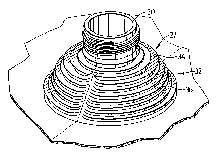
Figure 2 is a perspective view of the pouring spout of a container;

206631~
Figure 3 is a plan view of the pour spout of figure 2; and
Figure 4is a side view of the spout of figures 2 and 3.
The container in figure 1 is blow moulded of low density
S polyethylene and comprises a bottom wall 10, top wall 12, side walls 14 and
16 and front and rear walls 18 and 20 respectively. A collapsible spout 22is
formed in the top wall close to the junction of that wall with the front wall 18.
The parting line 24 extends centrally of the front, top rear and bottom walls
and through the spout.
The container is collapsible by folding the front and bottom walls
so that the junction line between those walls is moved to be parallel and
adjacent to the junction between the top and rear walls. In this arrangement,
each side wall is folded upon itself about lines extending from the front corners
15 of the top wall to the lower corners of the rear wall i.e., the side walls each
present double thickness triangular shapes.
From this position, the side walls are folded in the manner of a
gusset to bring the front edge of the top wall adjacent and parallel to the rear20 edge of the bottom wall.
In this prior art arrangement, the pouring spout comprises a
shoulder 26 of frusto-conical form being made up of a plurality of continuous,
concentric thick ridges joined by thin webs. Atop the shoulders is a rigid neck
28 which is externally threaded to receive a closure or other fitting such as a
spigot or conduit.

2066315
.
The spout is collapsible by applying d~wllwa~l (as viewed in
figure 1) force to the neck which causes the shoulder to fold, concertina style,into the interior of the container. To erect the spout, the neck is grasped, if
need be with a tool and pulled outwardly.
s
It is in the formation of the spout that the embodiment of figures
2 through 4 differs from the prior art structure. All other features are .simil~r.
As can be seen, particularly in figures 2 and 4, the spout 22
10 comprises an externally threaded, relatively thick-walled neck 30 which is
substantially rigid. The external thread suits the spout to receive a closure or
other fitting.
The shoulder 32 is of frusto-conical form and is made up of a
15 plurality of relatively thick concentric ridges 34 joined to each other by
continuous, concentric thin webs 36 which extend across the parting line.
It is to be noted that each ridge is in fact made up of two
part-ridges, each part-ridge being somewhat less than one half the
20 circumference of the ridge and termin~ting at each end short of the parting line.
The parting line is thus of subst~nti~lly constant thickness to all intents and
purposes about equal to that of the webs 36. It will be appreciated that when
one speaks of sub~t~nti~lly constant thickness in this context, one is cogni7~nt
of the usual limit~tions of this type if blow moulding technique. There is
25 almost always some flash at the parting line itself.

2066315
Essentially, the phrase means that the area is free of the major
variations in thickness which occur in the prior art structure where the ridges
extend across the parting line.
S With this arrangement, it is found that the tendency for there to
be pinhole flaws at the parting line in the region of the shoulder is subst~nti~lly
red~lced. It is also noted that collapsing and erecting the spout is made easier.

Representative Drawing
A single figure which represents the drawing illustrating the invention.
Administrative Status

2024-08-01:As part of the Next Generation Patents (NGP) transition, the Canadian Patents Database (CPD) now contains a more detailed Event History, which replicates the Event Log of our new back-office solution.

Please note that "Inactive:" events refers to events no longer in use in our new back-office solution.

For a clearer understanding of the status of the application/patent presented on this page, the site Disclaimer , as well as the definitions for Patent , Event History , Maintenance Fee  and Payment History  should be consulted.

Event History

Description Date
Time Limit for Reversal Expired 2006-04-18
Inactive: IPC from MCD 2006-03-11
Letter Sent 2005-04-18
Inactive: Late MF processed 2005-02-02
Letter Sent 2004-04-16
Letter Sent 2001-07-11
Inactive: Adhoc Request Documented 1998-04-16
Letter Sent 1997-04-16
Grant by Issuance 1995-07-18
All Requirements for Examination Determined Compliant 1993-01-11
Request for Examination Requirements Determined Compliant 1993-01-11
Application Published (Open to Public Inspection) 1992-11-07

Abandonment History

There is no abandonment history.

Fee History

Fee Type Anniversary Year Due Date Paid Date
MF (patent, 6th anniv.) - standard 1998-04-16 1998-04-14
MF (patent, 7th anniv.) - standard 1999-04-16 1999-04-12
MF (patent, 8th anniv.) - standard 2000-04-17 2000-04-17
MF (patent, 9th anniv.) - standard 2001-04-16 2001-03-30
Registration of a document 2001-04-16
MF (patent, 10th anniv.) - standard 2002-04-16 2002-04-10
MF (patent, 11th anniv.) - standard 2003-04-16 2003-04-09
MF (patent, 12th anniv.) - standard 2004-04-16 2005-02-02
Reversal of deemed expiry 2004-04-16 2005-02-02
Owners on Record

Note: Records showing the ownership history in alphabetical order.

Current Owners on Record
RELIANCE PRODUCTS LIMITED PARTNERSHIP
Past Owners on Record
PETER A. HAMM
Past Owners that do not appear in the "Owners on Record" listing will appear in other documentation within the application.
Documents

To view selected files, please enter reCAPTCHA code :


To view images, click a link in the Document Description column (Temporarily unavailable). To download the documents, select one or more checkboxes in the first column and then click the "Download Selected in PDF format (Zip Archive)" or the "Download Selected as Single PDF" button.

List of published and non-published patent-specific documents on the CPD .

If you have any difficulty accessing content, you can call the Client Service Centre at 1-866-997-1936 or send them an e-mail at CIPO Client Service Centre.

({010=All Documents, 020=As Filed, 030=As Open to Public Inspection, 040=At Issuance, 050=Examination, 060=Incoming Correspondence, 070=Miscellaneous, 080=Outgoing Correspondence, 090=Payment})


Document
Description 
Date
(yyyy-mm-dd) 
Number of pages   Size of Image (KB) 
Abstract 1995-07-17 1 10
Description 1995-07-17 5 157
Drawings 1995-07-17 4 87
Claims 1995-07-17 1 27
Representative drawing 1999-07-01 1 21
Maintenance Fee Notice 2004-06-13 1 173
Late Payment Acknowledgement 2005-02-28 1 165
Maintenance Fee Notice 2005-06-12 1 172
Fees 2000-04-16 1 46
Fees 1998-04-13 1 40
Fees 2001-03-29 1 45
Fees 1999-04-11 1 32
Fees 1997-04-15 1 34
Fees 1996-04-08 1 32
Fees 1995-04-17 1 34
Fees 1994-01-27 1 25
Correspondence related to formalities 1995-04-17 3 87
Prosecution correspondence 1992-04-15 5 175
Correspondence related to formalities 1995-04-24 1 35
Courtesy - Office Letter 1993-01-31 1 29
Prosecution correspondence 1993-01-10 1 28
Courtesy - Office Letter 1997-09-07 1 15
Correspondence related to formalities 1997-04-23 1 33
Courtesy - Office Letter 1995-05-10 1 22
Courtesy - Office Letter 1995-05-10 1 19
Correspondence related to formalities 2001-03-26 4 121
Courtesy - Office Letter 2001-05-13 1 8
Correspondence related to formalities 2001-06-03 1 26
Prosecution correspondence 2001-06-20 9 278
Courtesy - Office Letter 2001-06-11 1 18