Language selection

Search

Patent 2066621 Summary

Third-party information liability

Some of the information on this Web page has been provided by external sources. The Government of Canada is not responsible for the accuracy, reliability or currency of the information supplied by external sources. Users wishing to rely upon this information should consult directly with the source of the information. Content provided by external sources is not subject to official languages, privacy and accessibility requirements.

Claims and Abstract availability

Any discrepancies in the text and image of the Claims and Abstract are due to differing posting times. Text of the Claims and Abstract are posted:

  • At the time the application is open to public inspection;
  • At the time of issue of the patent (grant).
(12) Patent Application: (11) CA 2066621
(54) English Title: STATICALLY STABLE FRAME WITH FULL THERMAL BREAK FOR WINDOWS AND CLADDING PANELS
(54) French Title: CADRE ISOLANT POUR FENETRES OU PANNEAUX DE PAREMENT
Status: Dead
Bibliographic Data
(51) International Patent Classification (IPC):
  • E06B 3/26 (2006.01)
  • E06B 3/10 (2006.01)
  • E06B 3/263 (2006.01)
  • E06B 3/30 (2006.01)
(72) Inventors :
  • ROTH, FRITZ (Switzerland)
  • HARING, CHRISTOPH (Switzerland)
(73) Owners :
  • HARING AND CO. AG (Switzerland)
(71) Applicants :
(74) Agent: FETHERSTONHAUGH & CO.
(74) Associate agent:
(45) Issued:
(86) PCT Filing Date: 1991-07-22
(87) Open to Public Inspection: 1992-01-21
Examination requested: 1998-07-20
Availability of licence: N/A
(25) Language of filing: English

Patent Cooperation Treaty (PCT): Yes
(86) PCT Filing Number: PCT/CH1991/000152
(87) International Publication Number: WO1992/001853
(85) National Entry: 1992-03-20

(30) Application Priority Data:
Application No. Country/Territory Date
2425/90-5 Switzerland 1990-07-20

Abstracts

English Abstract


(57) Abstract

In order to obtain frames, in particular for windows, that without excessive
depths of construction provide insulating values approximately the same as those of the
insulating panes, a mechanically stable frame is disclosed, having a full thermal break
between inner (5) and outer frames, without any heat bridge. For that purpose, both
frames are composed of inner and outer continuous parts (6 and 9, 18 and 21) between
which is laid an insulating element (7, 20) capable of receiving and transmitting me-
chanical forces. The pane (4) to be mounted in the inner frame (5) is also thermally in-
sulated from the frame pans (6, 9, 12) by means of lip seals (11, 13). In order to seal the
gap between the inner (5) and outer (15) frames, at least one further lip seal (22) is pro-
vided.


Claims

Note: Claims are shown in the official language in which they were submitted.

Patent Claims

1. Frame construction for windows and facade
elements, including an inside and an outside frame (5,
15), between which an open groove is present at all
times, characterized in that each of the frames is
constructed as a sandwich element, whereby the inside
frame (5) has a mechanically tight, inner inside frame


part (6) running all the way around the window or the
like, to which are detachably attached, sealed from the
outside, a first insulation element (7) running all the
way around and a mechanically tight inside frame
transverse part (8) running all the way around, of
which the first is connected with an outer inside frame
part (9) running all the way around, with which in turn
is mechanically tightly connected an inside frame outer
part (12), the entirety arranged in such a manner that
a window glass (4) or a facade element can be supported
between first and second lip gaskets (11, 13) running
all the way around, connected with the inner inside
frame part (6) or the outer inside frame part (12) by
means of the pane-holding block (10) on site against
the first insulation element (7) and the outer inside
frame part (9), and in which the outside frame (15)
includes a mechanically tight inner outside frame part
(18) running all the way around, on which is detachably
attached, sealed from the outside, a second insulation
element (20) running all the way around the first,
which supports an outer outside frame part (21) running
all the way around, with which is mechanically tightly
connected an outside frame seal part (23).
2. Frame construction as in Claim 1,
characterized in that at least some of the following
frame parts are of wood: the inside frame inner part


(6) the inside frame transverse part (8) the outer
inside frame part (9) the inner outside frame part
(18) and the outer outside frame part (23).
3. Frame construction as in Claim 1 or 2
characterized in that the inside frame outer part (12)
and/or the outside frame seal part (23) are of aluminum
or special non-corrosive metals.
4. Frame construction as in one of the Claims 1
to 3 characterized in that the first lip gasket
extends over only a part of the first insulation
element (7) and the outer inside frame part (9) which
is attached to this on the outside.
5. Frame construction as in one of the Claims 1
to 4 characterized in that the outside frame (15) has
a third lip gasket (22) which seals the groove located
between inside frame (5) and outside frame (15).
6. Frame construction as in one of the Claims 1
to 5 characterized in that the insulation elements (7
20) are plates which can receive and transmit
mechanical forces, which are advantageously rigid foam
plates.


Description

Note: Descriptions are shown in the official language in which they were submitted.


2~6~621

9 :~: T H U 1 5 ~
. H . ~ ~ ~ S t~ I r--~r--~ E S ~ . t~ . ~ 2


(Translation)

PCT Internatlonal Ap~lIcatlon Publicatlon ~io.

W~ 92/018~3

Prlorlty date : Ju~y 22, 19g1; S~ltzerland
.

STATlCALLY STABL~ FR~vii~ WITH FUL~ ThiEi~MAL B~EAK FOR
WIN~OW~ ANr~ FACA~E EL~MENTS


The present Invcntlon r~lates to a statically
stablo trame wlth tull thermal break intended to frame
wlndows and ~acade elcmsnts as disclosed In the
d)sclosure part of Claim ~.
Wlndow trame structures for windows and for the
fixation of facade elements to a ~ullding have lnSi
~een known, i~ec~nt~y, howevor, the requlrement that
such constructlons have a hl~h insulation value, In

other words a low k-value and If at all possible no
cold brld~es, in other words that there should be a
complete thermal brcak, has galned In Importance.
Especially for th~ construction of wlndows, in recent
years conStructions have bcen known whlch att~ln
accepta~le avcrage insulation values with ~se of
t~o or three glass panes. The frames ~sed for that
type of constr~ctlon, corrcsponding to thc tashions
of th~ t Imc, have rnost ofton be~n rea~ized ot
plastlc or light rnetal~ pr~ dom I tl antly alumirlun1 and


. ~

2 ~ 2 1

T H 1_! 1 5: 2 1 H . J 1~ S P I E c~r--L_~ E ~: ~ ~ P _ 13 3


alumlnum alloy~ and do not attain the k-value of a~o~t
0.8 attainable by the multlplicity of ~la~s panes
For th~ most ie~rt, they assume constructions whlch do
not include complete thermal breaks and have an
ins~lation value or ~-value of approximately 1.7 or
h!gher which cons~quently is without any doubt poorer

.
insulatlon than that of the p~nes.
In modern conventional structures with rnasonry
wall parts or partlculariy solid wall parts whereln the
wlndow fram~s make up about 30~o of th~ facade surtace
this factual slt~atlon regardin~ poor Ins~lation Is a
considerable drawback. Therefore the oblect of the
invention Is to disclose a frame for windows and facac~e
elements which o~eroornes these drawbacks and
facilitatcs the attainment of a k-value of
approxlrmately 0.8.
Tinls Ob~oct Is attalne~ accordlng to the Invcntlon
by a tramo constructlon as de~cri~ed In Clalm 1.
One advantageous exem~lary embodlment of a frame
constructlon according to the Invention Is to be
described in the followin~ relative to the example of a
wlndow fram~ shown In the drawing. In the drawing -
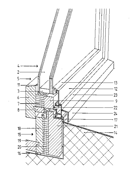
Flg. 1 is a vertical sect~on ~hrough a

perspeetive of a window with a frame
constr~ctlon aceordlng to tho Inventlon In
the region of the bottom vertical part of the


20~2~

1~r~-- 1 9--~ 2 T H u 1 ~ H ~ J fl 'f' S P I E~ G E L J E S C! . p,


framc,
Fi~. 2 Is a detail of t~e ind~vidua'
- elements o~ the frame shown ~n a vertical
cross section through the bottom vertical
fram~ part,
. .
'-ig. 3 Is a corr~sponding vertlcal cross
sectlon through a part of th~ fr~mc
constructlon at the sit~ of ~he pane^holding
block supportlng the glass panes, and
FiQ. ~ ~s a horizontal s~ctlon through ths
~rame In the region of one of its vertical
~, .
; parts.
A ciouble-pane wlndow wlth outslde pane 1 and
Inside, traditionally somewhat th~nner, pane ~, whlch
are advantageously held together in a known manner by
means o~ ed~lng crosspieces 3 to torm a double pane 4
anri to deflno the two sldes o~ a hollow space whlch Is
advantagQously evacuatgd or Is filled wlth inert gas or
dry alr is shown In F~gs. 1, 2 and 4. This double pan~ --
~, ~s wlth traditional windows, is advantageously
insertcd Into an inslde framrJ S to be abl~ to pivot at
least around ~ vertical axis, the frame advantageouSlY
,
consistln~ prlmarlly of wood and having an Inside ~ra~e

part 6 runnini~ all the way around the window, with
~; which 1~ conncctec a flrst insulation el~ment 7 whlch
lli<ewl~e run~ all the way around th~ wlndow ilement 7


. ~ .. .. . .

206~621

M ~ ~ -- 1 g -- ~ 2 T H IJ 1 ~ : Z ~ ~ J ~ Y S P I E G r--~ ~ s Q P ~ 5


is supporte~ on ~n inside frame transverse part 8 which
Is ~cchanlcally tightly connected w~th Ins~de frame
part 6 an~ supparts an outer inside frame part 9, whlch
~dvanta~eously likewise Is of wood. The cited first
in~latlon element 7 is a~vant~geou51y a ~andwlch
element wlth mechanlcal~y tight outsld~ pl~tes and a
rigid toam core, which can receive or resp~ctivelY can
transter forces, evon shearing forces, Into the outsids
frame.
As shown ~n F~g. 3, double pane 4 is supported in
a known manner ~n the region ot the plvot axis of the
winnow casement standing v~rtlcal and not vislble In
the d-awing by means o~ a pan~-holdin~ block 10
supported on ~Irst Insulation element 7 and oute-
inslde frame part 9. Between inner ~nside frame part
and double pane 4 and also br~tween first Insulation
elelnent 7 and outer Inslde frame part 9 and dou~le pane
i~ ~ is located a tlrst lip gasket ~1, whloh extends Into
tho reglon ot the tront of doublo pano 4 but
advantageously not over the cntir~ pane thickness, so
that condensation water which may appear ~n this reg~on
Is not found ~n a closed space and can flow out and/or
can be dlluted.
As shown In Flgs 1 to ~, an ins~de frflme outer

part 12 runnlng all the way around the w~ndow is
provided on the outside of outs;de p~ne 1, which part


: ,:

2~662:~

r~ 1 5-- S' ~ T H U 1 5: :2 3 H . J ~ S r~ ~ G r-- L, E~ Q _ P ~ 0 ~;


12 is connecteci through not shown s~Jpport elementS with
the out~r ins~de t~ame part 9 and is supported ~y means
of a second llp ~asket 13 against pane I and Insld~
frame 5I whlch In this case is configure~ as a window
casement sealed otf trom the outside. This Inside
frarne~outer part 12 can a~antageously conslst ot an
alumlnum proflle. Between it the two lip g~skets 11
and i3 doui~le pan~ 4 and outer insld~ fram~ part 9 Is
located a hollow spaco ~n which a~r is recirculated
o~on when the wlndow casement is closed since an
opening remalns permancntly b~tw~en ins(de ~rame oute~
part 12 and outer inside frame part 9.
AS is traditionally advantageou5 an outslde frame
15 Is supported on g~si<ets 16 17 an~ 17a on a masonry
or the like psrt 1q o~ the structure o~ a i~ulIdin9. It
Inclucies an inner outside frame part 18 running all the
way arOund whlch can b~ connected on its horlzontal
i~ottorn insldo surface wlth a wlndow slll 19 and to
which attacheg on tne outside ~ second Insulatin
olement 20 runn~ng all the way ~round and which
supports an outer outslde fra~e part 21 running all tho
way around the window
A thlrd lip gasket 22 running all the way around
the wlndow is advantageouslY connocted w~th the seCOnd
Insulatlon element 20 and the outer outsld~ trame part
21 and thls gasket on the ono hanci serves the Inslde


~ .

2 ~ 2 1

~r~ T H U 1 5: 2 ~ H . ._r~`~ sr~ I ~ G r- ~ r--~ ~.


i frame transverse part 8 when the window is ~eing
i clos¢d as a sott stop against outside frame 15 and on
i the other hand comPounds the seal over the ~roove found
between inside frame 5 and outside framo 15. The
outslde of th~s thir~ lip dasket 22 Is covered by an
outsid~ ~rame geallng oart 23 running all the way
around advantageOusly in the form of an alurnlnum
profile which can be conneCted in Its bottom
h~rizontal part with a covering profile 24 which
prevents the penetration of precipltation botween
outsi~e ~rame 15 and masonry 14. Outsld~ frame sealIng
member 23 is connected by rneans of not shown suPport
' elements wlth outer outslde frame part 21.
ît Is known to the expert that both Inslde and
outsido ~rames 5 and 15 cQn conslst ot statlcallY '~
stable constructlon elclnents wh~ch from the outslde
toward the Inslde have complete tharmal breaks and have
no cold bridgcs whatsocver. The descrlbed frame
constructlon oonsequontly optImally t~lfllls the
purpose of the present invention. It the various
dlfferent frarne parts 5 6 9 18 and 21 are wood and
rlgid 'foam plateg are used for insulation elcments 7
and 20 then a window trame accordlng to the invontlon
can ~e realizad without excess frame str~ctural
thlckncss sald wlndow frame havlng a k-value 0f 0.~ or

I lower and COnSequently havlng the insulatlon capacity


,:
.


.

201~6621

J~ R ~ ~ 2 T H U 1 S: ~: ~ H . J ~ ` S F~ r E: G E~ S ~ P _ e- 8


ot a ~ouble pane. The use of woo~ as pri~ary
constructlon material for the frame construction
according to the Ivention, as compared with plastic or
metal, also incorpora~es advantageous strength and
contact capacity Of COUrS8 plastlc or meta~ materlals
could ~180 be used, when certaln conditlons 80
...
indlcate.
~ lehougil the frams construotlon according to the
Inventlon has ~een described anci Illustrated relative
to a wlnciow, the exp~rt in the art is wel~ aware that,
wlth frame conStrUct~ons adapted to Indivldual relevant
condltlons, tor instance those of a concrete structure,
the Inslde frames can be reduc~d to the relevant
structure, and csn oven be use~ for flxln~ of facade
. . .
parts to bulldlngs.
,, . ' .

. ~-,; . . :
, . ~ .. ,,: ~ ,
.,: . '' ~ !, " . , ', ' ' ~ ' ' '


,


'

Representative Drawing
A single figure which represents the drawing illustrating the invention.
Administrative Status

For a clearer understanding of the status of the application/patent presented on this page, the site Disclaimer , as well as the definitions for Patent , Administrative Status , Maintenance Fee  and Payment History  should be consulted.

Administrative Status

Title Date
Forecasted Issue Date Unavailable
(86) PCT Filing Date 1991-07-22
(87) PCT Publication Date 1992-01-21
(85) National Entry 1992-03-20
Examination Requested 1998-07-20
Dead Application 2000-07-24

Abandonment History

Abandonment Date Reason Reinstatement Date
1999-07-22 FAILURE TO PAY APPLICATION MAINTENANCE FEE

Payment History

Fee Type Anniversary Year Due Date Amount Paid Paid Date
Application Fee $0.00 1992-03-20
Registration of a document - section 124 $0.00 1993-02-19
Reinstatement: Failure to Pay Application Maintenance Fees $200.00 1993-11-09
Maintenance Fee - Application - New Act 2 1993-07-22 $100.00 1993-11-09
Reinstatement: Failure to Pay Application Maintenance Fees $200.00 1994-07-27
Maintenance Fee - Application - New Act 3 1994-07-22 $100.00 1994-07-27
Reinstatement: Failure to Pay Application Maintenance Fees $200.00 1995-09-19
Maintenance Fee - Application - New Act 4 1995-07-24 $100.00 1995-09-19
Maintenance Fee - Application - New Act 5 1996-07-22 $150.00 1996-05-06
Maintenance Fee - Application - New Act 6 1997-07-22 $150.00 1997-05-26
Maintenance Fee - Application - New Act 7 1998-07-22 $150.00 1998-07-17
Request for Examination $400.00 1998-07-20
Owners on Record

Note: Records showing the ownership history in alphabetical order.

Current Owners on Record
HARING AND CO. AG
Past Owners on Record
HARING, CHRISTOPH
ROTH, FRITZ
Past Owners that do not appear in the "Owners on Record" listing will appear in other documentation within the application.
Documents

To view selected files, please enter reCAPTCHA code :


To view images, click a link in the Document Description column. To download the documents, select one or more checkboxes in the first column and then click the "Download Selected in PDF format (Zip Archive)" or the "Download Selected as Single PDF" button.

List of published and non-published patent-specific documents on the CPD .

If you have any difficulty accessing content, you can call the Client Service Centre at 1-866-997-1936 or send them an e-mail at CIPO Client Service Centre.


Document
Description 
Date
(yyyy-mm-dd) 
Number of pages   Size of Image (KB) 
Description 1994-03-12 7 195
Abstract 1994-03-12 1 18
Cover Page 1994-03-12 1 22
Claims 1994-03-12 3 67
Drawings 1994-03-12 3 123
Representative Drawing 1999-09-30 1 38
Prosecution-Amendment 1998-07-20 1 51
Prosecution-Amendment 1998-08-25 2 83
Fees 1993-12-06 3 57
Fees 1998-07-17 1 46
Assignment 1992-03-20 10 343
PCT 1992-03-20 10 350
Fees 1996-05-06 1 32
Fees 1995-09-19 2 56
Fees 1994-07-27 2 56
Fees 1993-11-09 2 45