Language selection

Search

Patent 2066884 Summary

Third-party information liability

Some of the information on this Web page has been provided by external sources. The Government of Canada is not responsible for the accuracy, reliability or currency of the information supplied by external sources. Users wishing to rely upon this information should consult directly with the source of the information. Content provided by external sources is not subject to official languages, privacy and accessibility requirements.

Claims and Abstract availability

Any discrepancies in the text and image of the Claims and Abstract are due to differing posting times. Text of the Claims and Abstract are posted:

  • At the time the application is open to public inspection;
  • At the time of issue of the patent (grant).
(12) Patent Application: (11) CA 2066884
(54) English Title: DEVICE FOR PHOTOMETRICALLY DETERMINING THE COAGULATION BEHAVIOUR OF BLOOD, BLOOD PLASMA OR THE LIKE
(54) French Title: INSTRUMENT PERMETTANT DE DETERMINER PAR PHOTOMETRIE LE PROCESSUS DE COAGULATION DU SANG, DU PLASMA SANGUIN ET D'AUTRES FLUIDES SEMBLABLES
Status: Deemed Abandoned and Beyond the Period of Reinstatement - Pending Response to Notice of Disregarded Communication
Bibliographic Data
(51) International Patent Classification (IPC):
  • G01N 33/49 (2006.01)
  • G01N 21/03 (2006.01)
  • G01N 21/25 (2006.01)
  • G01N 33/487 (2006.01)
  • G01N 33/86 (2006.01)
(72) Inventors :
  • EGGL, WILFRIED (Germany)
  • AMELUNG, ROLF (Germany)
(73) Owners :
  • HEINRICH AMELUNG, GMBH
(71) Applicants :
  • HEINRICH AMELUNG, GMBH (Germany)
(74) Agent: SMART & BIGGAR LP
(74) Associate agent:
(45) Issued:
(22) Filed Date: 1992-04-23
(41) Open to Public Inspection: 1992-10-25
Examination requested: 1999-03-08
Availability of licence: N/A
Dedicated to the Public: N/A
(25) Language of filing: English

Patent Cooperation Treaty (PCT): No

(30) Application Priority Data:
Application No. Country/Territory Date
P 41 13 330.7-52 (Germany) 1991-04-24

Abstracts

English Abstract


Abstract
Heinrich Amelung GmbH, Lehbrinksweg 59, 4920 Lemgo 1
1. Device for photometrically determining the coagulation behavior
of blood, blood plasma or the like.
2.1. A known device for measuring light waves of blood or blood plasma
has a receptacle seat which is provided with one or more
receptacle holders into each of which a receptacle filled with an
appropriate sample can be inserted from the top. Until now it has
been necessary, after the measuring of the light waves has been
completed, to take the respective receptacle out of the receptacle
holder from the top. A photometric measurement cannot take place
during this time Thus, it is the object of the invention to
shorten the chronological sequence of a photometric measurement.
2.2. To accomplish this, the receptacle holder (3) is provided with an
opening on its bottom side which can lead into a shaft (6). In
addition, the receptacle holder (3) has a leaf spring (8) with
which the sample to be measured can be held in the receptacle
holder (3).
2.3. This construction makes it possible to push the receptacle in
which the measurement has been completed downward with a new
receptacle to be inserted in the receptacle holder. It is no
longer necessary to remove it through the top, so that the removal
time is omitted and the chronological photometric measurement is
considerably shortened.
3. Figure 1.


Claims

Note: Claims are shown in the official language in which they were submitted.

Patent Claims
l. Device for photometrically determining the coagulation behavior of
blood, blood plasma or the like, having a receptacle seat which is
provided with at least one receptacle holder, into which a
receptacle which contains the blood, is transparent and preferably
rectangular in cross-section, can be inserted from the top, whereby
a light wave measuring device is placed in the area of the
receptacle holder,
characterized therein that the receptacle holder (3) has an opening
on its bottom side and that retaining means are provided in the
receptacle holder (3) with which the receptacle (2) can be held.
2. Device according to claim l, characterized therein that the
receptacle holder (3) corresponds approximately in its
cross-sectional dimensions to the cross-sectional dimensions of the
receptacle (2).
3. Device according to claim l, characterized therein that a shaft (6)
adjoins the opening, said shaft being larger in its cross-sectional
dimensions than the cross-sectional dimensions of the receptacle
(2).
4. Device according to claim 1, characterized therein that a leaf
spring (8), which projects into the receptacle holder (3), is
provided as retaining means.
5. Device according to claim l, characterized therein that the depth of
the receptacle holder (3) is less than the allotted height of the
receptacle (2) defined by a longitudinal edge.

-2-
6. Device according to claim 1, characterized therein that a removable
collecting container (7) is situated below the receptacle seat (1).
7. Device according to claim 1, characterized therein that, above the
receptacle seat (1), an incubator is provided which has incubation
shafts each of which is allocated to a receptacle holder (3),
whereby the incubation shaft and the allocated receptacle holder
have a common opening.

Description

Note: Descriptions are shown in the official language in which they were submitted.


?~
Heinrich Amelung GmbH
Lehbrinksweg 59
4920 Lemgo
Device for photometrically determining the coagulation behaviour of
blood, blood plasma or the like
... .. _ _
This invention concerns a device for photometrically determining the
coagulation behaviour of blood, blood plasma or the like according to
the preamble of claim 1.
To photometrically determine the coagulation behaviour of blood or blood
plasma, it is known to insert a transparent receptacle, provided wi-th an
appropriate sample, into the receptacle holder of a receptacle seat,
whereby the cross-section of the receptacle holder is adapted to that of
the receptacle, i.e. preferably rectangular. The photometric measuring
instrument consists of a transmitter situated in the area of the one
narrow side and of a receiver provided in the area of the other narrow
side.
Until now, the receptacle has been taken out of the receptacle holder
after the photometric measurement. This can be done manually. However,
automatic feed mechanisms are also known with which it is automatically
inserted and taken out.
In any event, it is considered disadvantageous that, as a result of thestep for removing the receptacle from the receptacle holder, a
relat1vely long period of time elapses until another light wave ?
measurement can take place.
.

2~8g~
-- 2 --
In particular when ~easur;ng many samples, as occurs for example in
med;cal laboratories, there are considerable economic disadvantages
since maximum use of the device cannot be made.
This disadvantage becomes especially aggravating when the receptacle
seat has a number of receptacle holders which are automatically
supplied; in this case, each time the receptacle is removed, for example
by a grip arm, this grip arm must travel back until the respective
receptacle can be deposited.
The time which the gripping device requires to travel back along the
path is, moreover, added to the actual removal time, so that a factor
results which precludes an effective operation.
On the other hand, the manual removal of the receptacle involves certain
risks since, when it is being removed, that is, when it is placed in
suitable containers, it is entirely possible that the attending staff
can come into contact with the contents of the receptacle.
It is, therefore, the object of this invention to construct a device ofthis type in such a way that it is possible to remove the receptacle
from the receptacle holder more quickly and easily and that, as a
result, operating the device becomes more economical.
This obJect is solved according to the invention by the features noted
in the charact~rizing part of claim 1.
These structural features mean that almost no time is required anymore
to remove the receptacles from the receptacle holder.
In principle, this means that the receptacle whose sample has been
measured and which is held in the receptacle holder, is pushed out by
the receptacle which is to be newly inserted into the receptacle holder,

2 ~ g ~
whereby the removed receptacle conveniently falls into a container which
is located below the receptacle seat.
In this case, it is advantageous if the receptacle to be ejected is
loosened from its locked position before the receptacle to be inserted
reaches its final locked position.
The retaining means with which the receptacle can be held can, for
example, be formed by springs with which the recep-tacle can be pressed
against the wall of the receptacle holder, whereby the receptacle is
then held by frictional contact.
Of course, it is also feasible to construct the retaining means in some
other way.
A further advantage of the invention is that the photometric measuring
device can now be connected to an incubator in which the sample -to be
measured is heated and maintained at a specific temperature and which
is, for example, placed directly above the receptacle holder.
In this case, the incubator would have a shaft corresponding to that ofthe receptacle holder, which is also provided with retaining means so
that, after the incubation time is ended, which is longer than the time
for photometrically measuring the receptacle below it, the heated
receptacle is brought into a position, while the receptacle held in the
receptacle holder is pushed out, which enables photometric measuring.
However, it is also feasible to remove the respective receptacle from aseparate incubator and insert it into the receptacle holder.
In any case, when a new receptacle is inserted, the one below it is
pushed out, ~hereby lt is advantageous if the size of the base area
.,
' . . .
: .

~6~
--~ 4 -
corresponds to the size of the top area, so that it is not possible for
two receptacles to become jammed or caught.
Additional advantageous embodiments of the invention are characterized
in the subclaims.
An embodiment oF the invention shall be described in the following with
reference to the attached drawings, showing:
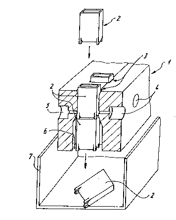
Fig. 1 a largely outlined sectional diagram of a device accordlng to
the invention,
Fig. 2 a partial lonyitudinal section through a receptacle holder of
the device.
Figure 1 shows a device for photometrically determining the coagulation
behaviour of blood, blood plasma or the like which-has a receptacle seat
1 in which several receptacle holders 3 are provided, spaced from one
another, which have a rectangular cross-section adapted to the
cross-section of a parallelepiped-shaped receptacle 2 and are open at
the front.
In this case, each receptacle holder 3 is to be provided with a
receptacle 2 from the top; this can be done manually or else by a
machine ~not shown3 which has a grip arm.
Every receptacle holder goes over into a sha~t 6 below ~tl the
cross-sectional dimensions of which are larger than the corresponding
cross-sectional d;mensions of the receptacle 2.
A transmittér holder 4 and a receiver holder 5 o~ a photometric
i

measuring device are provided in the receptacle seat 1, whereby the
transmitter holder 4 or the receiver holder 5, respectively, on the
opposite narrow sides of the receptacle holder 3, open into said
receptacle holder 3. The parts necessary for a photometric measurement
can be housed here.
A collecting container 7 is situated below the receptacle seat 1 in
which the receptacles 2 pushed out through shaft 6 are collected. This
collecting sontainer 7 can be designed and placed in such a way that it
can be removed and the collected receptacles 2 easily disposed of, as
required.
As can be very clearly seen in Figure 2, a retaining device in the formof a leaf spring 8, which projects into the receptacle holder 3, is
provided on the broadside of the receptacle holder 3.
The receptacle 2 placed into the receptacle holder 3 can be pressed
against the opposite wall of the receptacle holder 3 with help oF this
leaf spring 8 and is thus held in a certain position due to frictional
contact, so that unrestricted photometric measuring is made possible.
The leaf spring 8 is hereby placed in such a way that a receptacle 2
thus held is already moved out of the range of action of the leaf spring
8 when a new receptacle 2, inserted from the top. has not as yet reached
its final locked position. That is, prior to a new receptacle 2
reaching the end position, the receptacle 2 to be ejected already falls
through shaft 6 into the collecting container 7. The receptacle 2 can
be held in the receptacle holder only by frictional contact instead of a
leaf spring, whereby its cross-sectional dimensions must, of course,
quite accurately correspond to those of receptacle 2. In order to
guarantee a trouble-free -jection of receptacle 2 here, it is important
.
'
.. . ~ . . .
.
, .
.
:

f; 2 ~
that the depth of the receptacle holder 3 is less than the allotted
height of the receptacle 2.
: .:
.

Representative Drawing
A single figure which represents the drawing illustrating the invention.
Administrative Status

2024-08-01:As part of the Next Generation Patents (NGP) transition, the Canadian Patents Database (CPD) now contains a more detailed Event History, which replicates the Event Log of our new back-office solution.

Please note that "Inactive:" events refers to events no longer in use in our new back-office solution.

For a clearer understanding of the status of the application/patent presented on this page, the site Disclaimer , as well as the definitions for Patent , Event History , Maintenance Fee  and Payment History  should be consulted.

Event History

Description Date
Inactive: IPC from MCD 2006-03-11
Application Not Reinstated by Deadline 2003-04-23
Time Limit for Reversal Expired 2003-04-23
Deemed Abandoned - Failure to Respond to Maintenance Fee Notice 2002-04-23
Inactive: Status info is complete as of Log entry date 1999-03-23
Inactive: Application prosecuted on TS as of Log entry date 1999-03-23
Letter Sent 1999-03-23
Request for Examination Requirements Determined Compliant 1999-03-08
All Requirements for Examination Determined Compliant 1999-03-08
Inactive: Adhoc Request Documented 1997-04-23
Deemed Abandoned - Failure to Respond to Maintenance Fee Notice 1997-04-23
Application Published (Open to Public Inspection) 1992-10-25

Abandonment History

Abandonment Date Reason Reinstatement Date
2002-04-23
1997-04-23

Maintenance Fee

The last payment was received on 2001-04-19

Note : If the full payment has not been received on or before the date indicated, a further fee may be required which may be one of the following

  • the reinstatement fee;
  • the late payment fee; or
  • additional fee to reverse deemed expiry.

Please refer to the CIPO Patent Fees web page to see all current fee amounts.

Fee History

Fee Type Anniversary Year Due Date Paid Date
MF (application, 6th anniv.) - standard 06 1998-04-23 1998-04-07
Request for examination - standard 1999-03-08
MF (application, 7th anniv.) - standard 07 1999-04-23 1999-04-08
MF (application, 8th anniv.) - standard 08 2000-04-25 2000-04-07
MF (application, 9th anniv.) - standard 09 2001-04-23 2001-04-19
Owners on Record

Note: Records showing the ownership history in alphabetical order.

Current Owners on Record
HEINRICH AMELUNG, GMBH
Past Owners on Record
ROLF AMELUNG
WILFRIED EGGL
Past Owners that do not appear in the "Owners on Record" listing will appear in other documentation within the application.
Documents

To view selected files, please enter reCAPTCHA code :


To view images, click a link in the Document Description column. To download the documents, select one or more checkboxes in the first column and then click the "Download Selected in PDF format (Zip Archive)" or the "Download Selected as Single PDF" button.

List of published and non-published patent-specific documents on the CPD .

If you have any difficulty accessing content, you can call the Client Service Centre at 1-866-997-1936 or send them an e-mail at CIPO Client Service Centre.


Document
Description 
Date
(yyyy-mm-dd) 
Number of pages   Size of Image (KB) 
Representative drawing 1999-07-22 1 15
Cover Page 1993-11-27 1 21
Abstract 1993-11-27 1 30
Claims 1993-11-27 2 43
Drawings 1993-11-27 1 23
Description 1993-11-27 6 170
Reminder - Request for Examination 1998-12-29 1 116
Acknowledgement of Request for Examination 1999-03-23 1 178
Courtesy - Abandonment Letter (Maintenance Fee) 2002-05-21 1 183
Fees 1997-04-11 1 66
Fees 1996-04-09 1 43
Fees 1995-04-21 1 37
Fees 1994-02-22 1 27