Note: Descriptions are shown in the official language in which they were submitted.
~7~9~
OSK0 0 2
SPECIFICATION
Technical Field
The present invention relates to a metal tube oxidation
treatment apparatus, and relates particularly to a metal
tube oxidation treatment apparatus for carrying out the
inactivation treatment of the rnetal tube used in a super
high purity gas piping system and a super high vacuum
apparatus.
Background Technology
In recent years, the technology for realizing super
high vacuum, or the technology for producing a reduced
pressure atmosphere of super high purity by making a s~all
flow amount of a predetermined gas flow into a vacuum
chamber has become very important. These technologies are
widely used in the research of material charactaristics, the
formation of various kinds of thin films, the production of
semiconductor devices, etc., and as a result, although more
and more high vacuum degree has been realized, but it is
very strongly desired further t~ realize a reduced pressure
atmosphere in which the mixing of impurity elements and
impurity molecules has been reduced to the extreme limit.
For example, when it is exemplified with the case of
the semiconductor device, the dimension of unit elements has
become smaller year by year in order to improve the
assembling degree of the integrated circuit, and research
and development are actively carried out in order to
-- 1 --
2 ~ 5
practically obtaln the semiconductor devices having the
dimension of 1 ~m to submicron, and further, less than 0.5
~m.
The production of such a semiconductor device as
described above is carried out by repeating the procedure
for forming thin films, the procedure for etching the formed
thin films to a predetermined circuit pattern, etc. Then, in
the process such as described above, it is usual to carry
out the procedure in a super high vacuum state or in a
reduced pressure atmosphere in which a predetermined gas has
been introduced by putting the silicon wafers in general in
a vacuum chamber. If impurities are mixed in these
procedures, there are generated problems such as, for
example, the film quality of thin films is deteriorated, and
the accuracy of the fine finishing can not be obtained. This
is the reason why the super high vacuum and the reduced
pressure atmosphere of super high purity are requested.
As one of the greatest causes which prevented the
realization of the super high vacuum ancl the reduced
pressure atmosphere of super high purity, can be cited the
gas released from the surface of the stainless steel and the
like which are widely used in -the chamber and gas pipings.
Especially, it was the greatest pollution source that the
water adsorbed on the surface was separated out in vacuum or
in the reduced pressure atmosphere.
~ ig. 6 is a graph for showing the relationship between
the total leak amount of the s~stem added with the gas
piping system and reaction chambers in various kinds of
apparatus (the sum of the released gas amount from the
~7~95
piping system and the reaction chamber internal surface and
the external part leak) and the pollution of the gas. By the
way, it is assumed that the original gas does not perfectly
contain impurities. Plural number of lines in the figure
show the result of the cases in which the flow amount has
been changed to various values by making it as a parameter.
Although it is a matter of course, that the less the gas
flow amount becomes, the more the effect of the released gas
~- from the internal surface is xevealed, and the impurity
concentration becomes relatively high.
The semiconductor process has such a tendency as to
decrease the flow amount of the gas more and more in order
to realize the procedures of higher accuracy such as the
hole opening, the hole burying, etc. of high aspect ratio,
and for example, it is usual, for example, in the process of
submicron ULSI to use the flow amount of several ten cc/min
or the less. When it is assumed that the flow amount of 10
cc/min is -tentatively used, there is the system total leak
of about lo-3 to 10-6 Torr l/sec in such a manner as in the
apparatus widely used at present, the purity of the gas
becomes 1% to 10 ppm, and it becomes far from the one of the
high purity process.
- The present inventor has invented the supply sys-tem of
super high purity as, and has succeeded to check the leak
amount from the external part of the system to less than
lxlO-11 Torr-l/sec which is the detection limit of the
detector at present. However, due to the leak from the
inside of the system, that is, due to the constituents of
the released gas from the surface of the above-described
2~7~5
stainless steel, it was unable to reduce the impurity
concentratlon of the reduced pressure atmosphere. The
minimum value of the surface released gas amount obtained by
the surface treatment in the super high vacuum technology at
present, is in the case of the stainless steel is 1 x 10-
Torr l/(sec cm2), and even it is assumed that the surface
area exposed in the inside of the chamber has been estimated
to be smallest such as, for example, 1 m2, the leak amount
- becomes in total as 1 x 10⁻⁷ Torr l/sec, and the gas of the
purity of about 1 ppm can be obtained for the gas flow
amount of 10 cc/min. It is needless to say that the purity
decreases further, when the gas flow amount has been
diminished further.
In order to decrease the degassed constituent from the
internal surface of the chamber to about the same degree as
1 x 10-11 Torr-l/sec which is equal t~o that of the external
leak amount of the total system, it is necessary to make the
degassing from the surface of the stainless steel be less
than 1 ~ 10-15 Torr-l/sec cm2, and for that purpose, the
treatment technology of the surface of the stainless steel
for decreasing the gas release amount was strongly
requested.
- Also, in the semiconductor production process, various
kinds of gases such as from the comparatively stable general
gases (2t N2, Ar, H2, He) to the special gases having strong
reactivity, corrosive properties, and to~icity are used. In
general, as the material of the piping and chamber for
treating these gas, stainless steel is used in many cases
from the reasons such as the reactivity, anti-corrosiveness,
2~1~7~
high strength, the easiness of the secondary processability,
the easiness of the welding, and the easiness of polishing
the internal surface.
Stainless steel is excellent in the anti-corrosiveness
in a dry gas atmosphere. However, in special gases, there
are such ones as boron trichloride (BC13), boron trifluoride
(~F3), which show strong corrosiveness by forming
hydrogenchloride and fluoric acid when water is present in
the atmosphere, and in the case when water is present in the
gas atmosphere of the chlorine system and fluorine system
such as the above-described BC13 and BF3, stainless steel is
easily corroded. Therefore, after the surface polishing of
the stainless steel, the anti-corrosiveness treatment
becomes indispensable.
As the treatment method for the anti-corrosiveness,
there are the Ni-W-P coating and the like method (clean
escorting method) which covers stainless steel with a metal
having strong anti-corrosiveness, but in these methods, not
only cracks and pin holes are liable to be formed, but also
there are problems such as that the adsorption amount of
water on the internal surface and the residual constituents
of the solution become much, since they are the method of
using the wet type galvanization. As another method, can be
cited the anti-corrosiveness treatment in which a thin oxide
film is formed on the metal surface by the inactivation
treatment. Since stainless steel is inactivated by only
being immersed in a liquid, when there is present a
sufficient oxidizer in the liquid, the inactivation
treatment is carried out in general at ordinary temperature
~7~9~
or in a state where the temperature is somewhat raised in
immersing in a nitric acid solution. However, since this
method is also a wet method, rnuch water and residual
component of the treating solution are present in the piping
and on the internal surface of the chamber. In the above-
described methods, the presence of adsorbed water on the
internal surface gives severe damage to the stainless steel
in the case when the chlorine system and fluorine system
gases were made flown thereon.
Therefore, it is very important in the super high
vacuum technology and the semiconductor process to
constitute the chamber and the gas supply system with
stainless steel formed with an inactive state film which is
not subjected to damage even for a corrosive gas and has
little absorption and adsorption of water.
For example, in the inactivation treatment of the
stainless steel pipe, when the heat oxidation treatment has
been carried out in a high purity atmosphere in which the
content of water is less than 10 ppb, an inactive state film
excellent in the degassing characteristics can be obtained.
Fig. 7 shows the change of the water amount contained
in the purge ~as in the case when stainless steel pipes
having different internal surface treatment have been purged
at ordinary temperature. In the experiment, N2 gas was flown
in a 3/8" stainless steel pipe of the total length of 4 m at
the flow amount of 450 ccm, and the water amount contained
in the N2 gas at the outlet was measured by use of the
HYCOSMO ~low temperature optical dew point measuring
instrument).
9 ~
In Fig. 7, (a) shows the result of the test on the
stainless steel pipe having been electrolytically polished
on the internal surface.
The test shown in Fig. 7 has been carried out after the
sample has been left for about 1 week in a clean room of the
relative humidity of 50% and the temperature of 23C.
As is clearly known in (a) of the Fig. 7, it is known
that, in the electrolytically polished pipe, a large amount
of water is detected. After passing the gas for about 1
hour, about 100 ppb of water is also detected, and even
after 2 hours, the water amount is detected for about 50
ppb, and it is known that the water amount is not quite
decreased.
On the contrary, it was elucidated by the present
inventor that the process has extremely excellent degassing
characteristics in the case when the inactivated state film
has been formed in a high purity dry atrnosphere.
However, it is necessary to make the water content be
less than 10 ppb in order to produce a stainless steel pipe
having the extremely excellent degassing characteristics of
the adsorbed gas, and in order to realize the super high
purity oxidation atmosphere, the condition control of a high
degree is necessary, and the process has high cost and its
production efficiency is bad, so that the process could not
be said as to be suitable to mass production. That is, by
use of the conventional generally used metal oxidation
treatment apparatus and the metal oxidation treatment
method, it was unable to realize the oxidation atmosphere of
such a super high purity as described above.
-- 7 --
~7~5
~ lso, especially in the stainless steel pipes having
small internal diameter of such as 1/4", 3/8" and 1/2", the
oxidation treatment has been carried out in such a state as
it is that the inside of the stainless steel pipe has been
exposed to the ambient air atmosphere and has been polluted.
Also, since the external side of the stainless steel pipe
has in general no relationship to the characteristics, it is
very much polluted in comparison to the internal surface.
When there is such a case that the gas contacting to this
external surface is mixed to the gas for treating the
internal surface, it is very difficult to keep the super
high purity degree of the gas for treating the internal
surface, and an inactivated film of good quality which is
excellent in the corrosiveness and having little occlusion
and adsorption of water can not be formed. Also, in the
external side of the stainless steel pipe, the surface after
the oxidation treatment becomes dirty by the roughness and
dirtiness of the surface. Due to the fact that the external
side of this stainless steel pipe oxidized becomes the cause
of problems such that the pipe looks dirty and par-ticles are
generated in the case when it was piped in a clean room,
together with that an inactivated state film of good quality
can not be formed on the internal surface.
Therefore, in the mass production technology of the
inactivation treatment of the metals to be oxidized such as
the stainless steel pipe and the like, it was desired to
establish the technology in which the external surface is
not oxidized, together with that an inactive state film
having excellent anti-corrosiveness and little occlusion and
2~7~9~
adsorption of water is formed.
Therefore, the apparatus shown otherwise in Fig. 8 has
bee proposed as such a technology (Japanese Patent
Application No. 195185/1988).
In the apparatus shown in Fig. 8, a groove 134 having
the diameter of approximately the same as the external
diameter of the stainless steel pipe 101 is formed on the
one surface, and the introducing port 135 and exhausting
port 136 of the gas are formed on the another surface, and
further, a pair of holders 103 and 109 which has
communicated the groove 134 to the introducing port 135 and
the exhausting port 136 is used, and further, the apparatus
has such a structure that an inactive gas is introduced into
the oxidation treatment furnace 137 from 119 and can be
exhausted from 121.
The stainless steel pipe 101 is inserted into the
groove 134 at the end thereof, and are held on the holders
103 and 104. Also, in another surfaces of the holders the
gas introducing pipe 107 and the gas exhausting pipe 109 are
connected.
That is, as the maximum feature of this technology, in
the oxidation treatment furnace 137, while the gas is
introduced form one end of the stainless steel pipe lOlr ad
the gas is always exhausted from another end, and impuriti.es
of the water separated from the internal surface of the
stainless steel pipe 101 as the metal -to be oxidation
treated is exhausted out of -the oxidation -treatment furnace
137, and the stainless steel pipe 101 can be hea-t oxidized
in a dry oxidation treatment atmosphere. Thereby, the water
_ g
2~67~95
concentration in the oxidation treatment atmosphere can be
decreased to less than the value objected (for example, less
than 10 ppb in the case of the stainless steel), and the
formation of a good inactivated state film on the surface of
the metal to be oxida-tion treated is enabled.
Also, even if it is a stainless steel pipe in which the
gas is difficultly flown, such as the stainless steel pipe
and the like having small internal diameter, since the inlet
and the outlet of the gas are arranged in such a manner that
both ends of the stainless steel pipes are contacted, it
becomes possible that the oxidation treatment atmosphere gas
is flown in the inside of the stainless steel pipe, and the
metal processed is heat oxidized in a dry oxidation
treatment atmosphere. Thereby, the water concentration in
the oxidation treatment atmosphere can be reduced to less
than the objected value (for example; less than 10 ppb), and
the formation of good inactivated state film on the surface
of the metal processed becomes possible.
However, it was understood that the following problems
are generated in this technology.
(1) At first, it is difficult to insert the stainless
steel pipe 101 in the groove 134 of the holders 103 and 104.
That is, when the internal diameter of the groove 134 is
made too larger than the external diameter of the stainless
steel pipe 101, there is generated a gap between the groove
134 and the stainless steel pipe 101, and the oxidative gas
flows into the oxida~ion treatment furnace 137, and together
with that an activated state film of good quality can not be
formed on the internal surface of the stainless steel pipe
- 10 -
~ID670~
lO1, the external surface is also oxidized, and in order to
prevent such a phenomenon, i-t is necessary that the internal
diameter of ~he groove 134 is made approximately the same
with the external diameter of the stainless steel pipe 101.
However, when the internal diameter o-f the groove 134 and
the external diameter of the stainless steel pipe 101 are
made approximately be in the same size, the insertion of the
stainless steel pipe in the groove 134 becomes difficult.
Especially, in the case when the stainless steel 101
has long length or has a small diameter, the difficulty is
further increased.
Also, it is also difficult to finish the internal
diameter of the groove 139 with good accuracy such that it
is approximately the same with the internal diameter of the
stainless steel pipe 101.
(2) Secondly, even if the finishing of the groove could
be finished with good accuracy, in the case when fluctuation
is present in the external diameter of the stainless steel
pipes, the insertion into the groove 134 becomes impossible,
when the external diameter is large, and on the contrary,
when the external diameter is small, a gap is generated as
has been described above, and together with that an
inactivated state film of good quality can not be formed on
the stainless steel pipe lOl, external surface burning is
generated on the external surface. By the way, such an
external burning is liable to be generated at the end part
of the stainless steel pipe 101.
~ 3) Since the gap between the holders 103 and 104 of
the stainless steel pipe is constant, in the case when
7~95
fluctuation was present in the length of the stainless steel
pipe, then, as shown in Fig. 9, gap is generated between the
groove 134 and the stainless steel pipe lOls in the case of
a short stainless steel tube lOls, and an oxidative gas
flows into the oxidation treatment furnace 137 from the gap
thereof, and together with that inactivated state film of
good quality can not be formed on the internal surface as
described in ~1) and (2), and there ls generated the
external surface burning.
(4) When the elongation by thermal expansion is
generated in the stainless steel pipe 101 at the time of
heating, deformation is generated in the pipe processed,
since its both ends are restricted. When play is made to be
present in order to prevent the deformation, the oxidative
gas flows into the space of the oxidation treatment furnace
from the inlet as described in (3), ànd together with that
an inactivated state film of good quality can not be formed
on the internal surface of the stainless steel pipe, but
also the external surface is oxidized.
(5) In the case when the stainless steel pipe is a long
length pipe, bending due to the weight of itself is
generated at the central part.
By the way, the above-described problems were found out
by the present inventor, and the present invention has been
carried out on the basis of the discovery of such problems.
Disclosure of the Invention
The metal pipe oxidation treatment apparatus of the
present invention comprises an oxidation treatment furnace
having an inert gas inlet for introducing inert gas into the
- 12 -
inside and an inert gas outlet for outletting the inert gas
to outside; the first hollow member for supporting the pipe
processed at one end thereof in said oxidation treatment
furnace, and together with that, for introducing the gas
from the outside of said oxidati.on treatment furnace
uniformly into respective stainless steel pipes 101 in said
pipes to be processedi and the second hollow member for
outletting the gas to the outside of the oxidation treatment
furnace from the pipe processed, together with that for
supporting the pipe processed a-t another end thereof in said
oxidation treatment furnace, and is characterized by that
the supporting part of the pipe processed in said first
hollow member and said second hollow member is made in
tubular form, and on the outer periphery of said tubular
member, a tapered portion with outer diameter gradually
decreasing toward the tip is formed, and further, a spring
is mounted at a suitable position of sa:Ld second hollow
member in such a manner that said second hollow member can
displace to the long length direction of the pipe processed.
Also, it comprises an oxidation treatment furnace
having an inert gas inlet for introducing inert gas into
inside, an inert gas outlet for outputting the inert gas to
outside; the first hollow member for introducing the gas
from the outside of said oxidation treatment furnace
uniformly into respective stainless steel pipe 101 in the
pipes processed, together with that the pipe processed is
supported at one end thereof in said oxidation treatment
furnace; and the second hollow member for outletting the gas
from the pipe processed to outside of the oxidation
2~6~095
treatment furnace, together with that the pipe processed is
supported at another end thereof in said oxidation treatment
furnace, and is characterized by that the supporting part of
the pipe processed in said first hollow member and said
second hollow member is made in a tubular form, and a taper
in which the external diameter gradually decreases is formed
on the external circumference of said tubular body, and a
covering pipe is provided in the external side of the
tubular body of said first hollow member in such a manner as
to cover said tubular body, and the space formed between
said tubular body and said covering pipe is made to
communicate to the outside of said oxidation treatment
furnace.
Further, it comprises an oxidation treatment furnace
having an inert gas inlet for introducing inert gas into
inside, and an inert gas outlet for exhausting inert gas to
the outside; the first hollow support member for introducing
the gas from the outside of said oxidation treatment furnace
uniformly into respective stainless steel pipes 101 to be
processed, together with that the pipe processed is
supported at one end thereof in said oxidation treatment
furnace; and the second hollow support member for outletting
the gas from the pipe processed to the outside of the
oxidation treatment furnace, together with that the pipe
processed is supported at another end thereof.
The supporting part of the pipe processed in said first
hollow member and said second hollow member is made in a
tubular form, and on the outer periphery of said tubular
member, a tapered portion with outer diameter gradually
- 14 -
~67~9~
deceasing toward the tip is formed, and furthex, at least
one hole has been provided in the vicinity of the terminal
part of said -tubular body of said second hollow supporting
member.
Performance
(Claim 1)
In the present invention, the supporting part of the
supporting member is made in a tubular form, and a tapered
part is provided on the outer periphery thereof, and
further, since a spring i.s mounted to be displaceable, it is
possible to support the stainless steel pipe on the
supporting part easily. Also, even if there is fluctuation
in the length of the stainless steel pipe, no gap is
generated between the supporting member and the stainless
steel pipe, since the supporting member is always pushed to
the stainless steel pipe, and an inactivated state film of
good quality can be formed on the internal surface, and
together with that, the external surface burning is
prevented. Also, the "gasket" which becomes an article of
expenditure is not used and the re-finishing and re-cleaning
of the pipe terminal is not necessary, and the cost down and
the improvement of the productivity become simultaneously
attained.
(Claim 2)
In the present invention, a cover tube is provided in
such a manner as that it covers the tubular member of the
first supporting member, and moreover, since the space
formed by the tubular member and the cover tube is made
communicated to the outside of the oxidation treatment
- 15 -
~`70~5
furnace, even if oxidative gas is diffused from the pipe
processed to the outside of the oxidation treatment furnace,
this oxidative gas does not contact the pipe processed and
is released to outside, and the external surface burning in
the vicinity of the first support member of the pipe
processed can be prevented.
(Claim 3)
In the present invention, since a hole is provided in
the vicinity of the end part of the tubular member of the
second support member, even if an oxidative gas is diffused
from the pipe processed to the outside of the pipe
processed, since this oxidative gas is exhausted to the
outside of the oxidation treatment furnace, the external
surface burning in the vicinity of the second support member
of the pipe processed can be prevented.
Brief Explanation of Drawings
Figs. 1 to 5 relate to the embodiment of the present
invention, and Fig. 1 is a partial side sectional view of
the appara-tus; Fig. 2 is an enlarged view of the support
member; Fig. 3 is a front view of the sword guard form
member; Fig. 4 is a side view for showing the receiving
step; Fig. 5 is a gas supply system circuit diagram; Fig. 6
is a graph for showing the relationship between the leak
amount of the apparatus and the impurity amount; Fig. 7 is a
graph for showing the gas exhaustion amount; Figs. 8 and 9
are the apparatus side sectional view for showing the prior
examples.
(Explanation of Symbols)
101 metal tube to be oxidation treated (stainless
- 16 -
2~7~9~
steel tube),
lOls stainless steel tube,
102 oxidation furnace chamber.
103 first support member (first holder),
104 second support member (second holder),
107 gas introducing line, 108 gas line,
109 gas exhausting line,
llOa,llOb exhaust line, llla, lllb flow meter,
114a,114b,114c,114d,115a,115b stop valve,
116a,116b,116c,116d mass flow controller,
119 inert gas, 122 heater, 123, 124 furnace lid,
125,126 heating heater, 134 groove, 135 inlet,
136 outlet, 137 oxidation treatment furnace,
13~ tubular member, 139 spring, 140 flange,
141 sword guard form member, 141a notch,
142 core tube, 143 joint ~fléxible tube),
144 castor, 145 purge use gas supply line,
145' inlet, 146 oxidative gas supply line,
151 inert gas inlet, 152a,152b, inert gas outlet,
160 covex tube, 167, 168 taper (seal part),
170 hole, 1~0 support member flange,
190 exhaust system, 191 float type flo~meter,
807,808 spiral tube, 809,810 needle valve.
Best Form for Carrying out the Invention
In the following, explanation will be given on an
embodiment of the present invention by referring to
drawings .
Fig. 1 is an outline diagram of the apparatus for
showing an embodiment of the present invention.
~67~
In the present example, in a metal tube oxidation
treatment apparatus comprising an oxidation treatment
furnace 137 having an inert gas inlet 151 for introducing
inert gas into the inside of the oxidation treatment furnace
137 and inert gas outlets 152a, and 152b; a holder 103 as
the first hollow member for uniformly in-troducing the gas
from the outside of the oxidation treatment furnace 137 into
a plural number of stainless steel tubes 101 in said heating
furnace 102; and a holder 104 as the second hollow support
member for exhausting the gas in the stainless tubes 101 to
the outside of the oxidation treatment furnace 137! toget~er
with that the stainless steel tube 101 is supported at one
end thereof in said oxidation treatment furnace 137; the
support part of the stainless steel tube 101 in the holder
103 and the holder 104 are made in a tubular form 138, and
on the outer periphery of said tubular mernber 138, tapers
167 and 168 which gradually decease in external diameter
toward the tip are provided, and further, a spring 139 is
provided on the holder 109 in such a rnanner as that the
holder 104 can displace to the lengthwise direction of the
stainless steel tube 101.
In the following, more detailed explanation will be
given on this apparatus.
In Fig. 1, numeral 101 denotes a stainless steel tube
as the rnetal tube to be oxidation treated, and in general,
it is an internal surface electrolytically polished tube of
SUS 316L material of the diameter of about 1/4", 3/8"l and
1/2", and a plural number of constant length pipes of 4 m
length are received. It is needless to say that the
- 18 -
2~7~95
diameter, ].ength, material may be other than those described
above.
Numeral 102 denotes an oxidation furnace chamber, and
in the case when heating oxidation treatment has been
carried out, it is preferable to make it with stainless
steel subjected to the internal surface electrolytic
polishing and inactivation treatment of the stainless steel.
In the oxidation treatment furnace 137, an inert gas inlet
151 for introducing inert gas into inside and inert gas
outlets 152a and 152b are provided. The inert gas inlet 151
is provided at the contrary side (upper right side in the
figure) to the entrance and exit side of the stainless steel
tube, and the inert gas ou-tlet is preferably provided at the
entrance and exit side (upper left side in the figure). When
they were provided in such a manner as described above, even
when the furnace lid 123 has been opened at the time of
receiving the holders 103 and 104, the flow-in of the
atmospheric air into the oxidation treatment furnace 137 can
be made minimum, since inert gas flows from the contrary
side of the entrance and exit side to the entrance and exit
side. As a result, the pollution of the internal wall of the
oxidation chamber 102 by the atmospheric air can be made
minimum, and together with that the purge of the inside of
the oxidation furnace chamber 102 can be carried out in a
short time, but also, there is the effect of cooling in such
a manner that mal-performance due to the burning and the
like is not generated in the caster 144.
Numeral 103 denotes a holder as the first support
member for supporting this side end of the stainless steel
-- 1 9 --
~0670~5
tube 101, and for introducing gas from outside of the
oxidation treatment furnace 137 into the stainless steel
tube 101, and numeral 10~ denotes a holder as the second
support member for the interior side end of the stainless
steel tube 101, and for exhausting the gas to the outside of
the oxidation treatment furnace 137. In the first support
member 103 and the second support member 104, the support
part is formed as a tubular member 138 for corresponding to
the inside shape of the stainless steel tube 101, and
fuxther, on the outer periphery of the tubular member 138,
there is formed a taper 167. This taper gradually decreases
toward the tip, and becomes smaller than the internal
diameter of the stainless steel tube 101.
Also, since a spring 139 is mounted on the second
support member 104, the second support member 104 is
displaceable in correspondence to the stress from outside.
In the present example, the second support member flange 140
is put on slidably, and the spring 139 i~s mounted between
the flange 140 and the support member 104. Therefore, in the
case when the stainless steel tube is to be supported, one
end of the stainless steel tube 101 is inserted into the
tapered part 167 of the first support member 103 in such a
state that the second support member has been pulled ~o
somewhat interior side (right side on the figure), and after
inserting another end of the stainless steel tube 101 into
the tapered part 168 of the second support member 104, when
the second support member is released, the stainless steel
tube 101 can be easily made be supported on the support
members 103 and 109.
- 20 -
~6~
Also, since the spring 139 such as described above is
provided, even w~en the stainless steel tube 101 has
expanded in the oxldation treatment time, deformation due to
the heat expansion is not generated, since the second
support member 109 displaces in correspondence to expansion.
Further, since a spring 139 is provided on the second
support member 109, a force for displacing to the left side
on the figure acts on the second support member 104, since a
spring 139 is provided on the second support member 104, and
moreover, since a taper 167 is formed on the tubular member
138, the tubular member 138 hermetically adheres to the
internal surface of the end part of the stainless steel tube
101, and no gap is generated between both members.
Further, a force directed to left side in the figure is
applied to the stainless steel tube lOlt and the left side
of the stainless steel tube 101 is pushed to the tubular
member 138 of the first support member 103, and since a
taper 167 is formed on this tubular member 138, so that even
if when the fluctuation of the left end diameter of the
stainless steel tube 101 or the fluctuation of the length is
present, gap is not generated between the stainless steel
tube 101 and the first support member 103. As a result, the
external surface burning and the like is not generated in
the stainless steel tube 101.
By the way, in the present example, the support member
103 is fixed to the hollow core tube 142, and the support
member lOq is put in the hole of the flange lqO provided on
the core tube 192 to be slidable. Further, the gas outlet
side end of the support member 109 and the hollow part of
- 21 -
2~7~9~
the core tube 192 are connec-ted to the flexible hollow joint
143. When the support members 103 and 104 are provided on
the core tube 192 in such a manner, whole members form one
unit and unification becomes possible, and the reception of
the core tubes 192 and the like in-to the oxidation furnace
chamber 102 becomes easy.
Further, a castor 144 is provided at the end part of
the core tube 142, and the reception has become easier.
- By the way, when a sword guard form member 141 having
notches 141a of a predetermined dimension such as are shown
in fig. 3 is provided on the core tube 142, the mounting of
the tubes becomes easily possible by only inserting the
stainless steel tube 101 into the notches 141a. By the way,
the words "predetermined dimension" means the dimension at
which the central axis of the stainless steel tube lOl
appxoximately coincides to the cent~al axis of the tubular
member 137 of the support members 103 and 104 on the state
of the stainless steel tube 101 is inserted into the notches
141a of the sword guard form member 141. Also, it can not
only prevent the generation of bending in the central part
of the stainless steel tube 101, but also, the position
determination of the stainless steel tube lOl can be also
easily carried out. By the way, it is preferable that
stainless steel is used in this sword guard form member 141,
when such facts are considered as out gas free, particle
free, heat expansion, etc.
Further, when at lest one hole 170 for communicating to
the inside is provided at somewhat interior side from the
tapered part of the second support member 104, even if when
- 22 -
2~67~
the oxidative gas intends to diffuse from the tapered part
168 as the seal part of the stainless steel tube 101 and the
holder 104 to the oxidation furnace chamber 102, it is
recycled through the hole 170 together with the.atmosphere
gas of the outside of the oxidation treatment furnace 137
and exhausted to the outside, thereby the inactive
atmosphere of the oxidation furnace chamber 102 can be
~ preserved and the external surface burning can be prevented.
- On the other hand, diffusion of the oxidative gas is
generated at the side of the holder 103 in the same manner
as in the holder 104 side, and although external surface
burning occurs on the stainless steel tube of the holder 103
side, but when a hole such as the same with that in the
holder 104 side, the atmosphere gas of the chamber 102 mixes
into the stainless steel tube 101 (since the holder 103 side
is in the upstream of the oxidative ~as), and together with
that the gas concentration in the stainless steel tube 101
becomes unable to be controlled arbitrally, and the internal
surface of the stainless steel tube 101 quitely receives the
effect of the contamination of the out gas from the chamber
. 102, although its arnount is minute. Therefore, in order to
solve such maleffect as described above, together with the
prevention of the external surface burning, a over tube 160
is formed at the outside of the tubular member 138 in such a
manner as it covers the tubular member 138 and forms double
tube structure, and it will do that the system 190 for
communicating the space formed with the tubular member 138
and the cover tube 160 to the ou-tside of the oxidation
treatment furnace 137 is provided other than the system for
- 23 -
2 ~ 9 ~
introducing the gas of the internal surface treatment use
~oxidative gas). When the constitution such as described
above is adopted, even if the oxidative gas diffuses to the
outside via the seal part 167, since the gas is exhausted to
the outside of the oxidation treatment furnace 137 via the
system 190, the prevention of the external surface burning
of the stainless steel tube 101 becomes possible. By the
way, it will do that the flow amount of the gas exhausted
via the system 190 is controlled by use of a float type flow
meter 191.
Numeral 107 denotes the gas introducing line for
supplying the purge gas (for example, Ar, N2, etc.) and the
oxidation treatment atmosphere gas (for example, 2 and the
like). This introducing line 107 is connected to the inlet
145 formed on the support member 103.
On the other hand, numeral 109 denotes the exhaust line
for exhausting the gas passed through the gas introducing
line 107, the first hollow support member 103, inside of the
stainless steel tube 101, the second hollow support member
104, flexible tube 143, and the inside of the hollow core
tube 142 to the outside of the oxidation treatment furnace
137, and is connected to the end of the core tube 142.
Numeral 151 denotes an inert gas inlet for supplying
the inert gas (for example, Ar) into the oxidation furnace
chamber 102 for preventing the pollution due to that the
external surface of the stainless steel tube 101 is
oxidized, by making the external surface of the stainless
steel tube 101 be in inert atmosphere, and is connected to
the gas line 108. Numerals 152a and 152b denote inert gas
- 24 -
2~6r7~95
outlets for exhausting inert yas to outside of the oxidation
treatment furnace 137, and are connected to the exhaust
lines 110a and 110b.
In the figures, numerals llla and lllb denote flow
amount meters (for example, float type flow meter), and
116a, 116b, 116c, and 116d denote mass flow controllers.
The mass flow controllers 116a to 116d can set and
control mass and flow amount to be constant notwithstanding
the pressure in the furnace. The flow meters llla and lllb
have needle valves built-in, and can adjust the pressure in
the furnace by the open degree of the needle valve. Thereby,
arbitrary pressure difference and flow amount can be set in
and out of the stainless steel tube 101.
Numerals 114a, ll9b, 115a and 115b denote stop valves.
Numeral 122 denotes a heater as the heating member for
heating the oxidation furnace chamber 102. In order to
obtain the uniformity of the oxidation treatment
temperature, the furnace 122 is divided in 6 zones in
length-wise direction, and in respective zones, temperature
can be set to independent set values. Thermocouples are
attached at various positions by passing thermocouple insert
use boat 192 in the stainless steel tube 101, and by
regulating 6 set values while measuring actual temperature
on the stainless steel tube 101, temperature difference on
the stainless steel tube 101 is made as little as possible,
and uniform treatment becomes possible.
Also, by the above-described effect, sufficient
temperature uniformity can be obtained without carrying out
preliminary heating. However, pipe is made in a spiral form
25 -
f~ O 9 5
in the interval between the oxidation use gas inlet 145 and
the holder 103, and the length in this interval is made
sufficiently long, and when that part is made as a
preliminarily heating zone, the oxidative gas is heated
almost to the temperature in the furnace and is introduced
into the stainless steel tube 101.
(Receiving Procedures)
In the following, explanation will be given on the
function and manipulation procedures of this apparatus by
referring to drawings.
Fig. 4 is a state diagram in the case when the units
has been taken out of the oxidation furnace chamber 102, and
is in the preliminary state befo.re receiving the stainless
steel tube. In the inactivation treating technology, since
the purity degree of the treating atmosphere thereof gives
large influence to the film thickness and film quality of
the formed inactivated state film, it is necessary to open
the sample in an atmosphere as clean as possible. For this
purpose, the state of opening the inside of the oxidation
furnace chamber 102 to the atmosphere is made as short as
possible for a time, and the pollution of the inside of the
oxidation furnace chamber 102 is prevented utmost.
When this pollution by the atmosphere is considered, it
is most preferable to take the method that the opened
furnace lid to be opened is made be the furnace lid 123 as
shown in Fig. 1, and from the furnace lid 124 side, the pug
use gas (for example, Ar) is continued to be flown, and the
mixing of the atmosphere constituents into the o~idation
treatment furnace 137 is prevented.
-- 26 -
~7~9~
One end of the stainless steel tube 101 is inserted in
the taper 167 of the tubular member 138 of the first hollow
support member 103 (Fig. 4(a)). Nex-t, the stainless steel
tube 101 is put in the notch of the sword guard form member
191 (Fig. 2(b)). In that case, the second support member 104
is kept in somewhat pulled state.
Subsequently, when the second support member 10~ is
released, the taper of the tubular member of the second
support member 104 is inserted into another end of the
stainless steel tube 101. By repeating these procedures, a
plural number of stainless steel tubes are made supported on
the support member (Fig. 9(d)).
Next, the assembly is received into the unit oxidation
furnace (Fig. 9(e) to 9(f)).
Fig. 4(f) shows the sate where the unit, in which the
stainless steel tube 101 has been su~pported, is received in
the inside of the oxidation furnace chamber 102. In this
state, the purge use gas (for example, Ar) is flown in the
inside of the stainless steel tube 101 and into the
oxidation treatment furnace 137, and the atmosphere in the
oxidation treatment furnace 137 and in the stainless steel
tube 101 polluted by being exposed to atmosphere is replaced
to an inert gas atmosphere. For the removal of the
atmosphere constituents, the vacuum purge for repeating the
vacuum exhaustion and the gas charging is especially
effective. Also, for the removal of adsorbed molecules such
as H2O and CO2 of the oxidation chamber 102, the unit, etc.,
the "baking" for effecting evacuation and the inert gas
purge in heated state of about 120C is especially
- 27 -
~67~
effective. At this time, at first, the reason why the temperature
of about 120C is selected is that the dense film containing no
water as the treatment object of the present apparatus can not be
obtained, since when oxidation is started during the time when
the oxidative gas such as the residual O~ and the like can not
yet be remoYed, oxidized film containing water grows up.
Next, baking and purge of the oxidation treatment furnace
137 and the stainless steel tube 101 are carried out. The baking
is carried out at the same temperature as that of the oxidatlon
temperature (for example, 400C to 550C) until the water amount
in the gas from the outlet becomes less than about 5 ppb.
After finishing the baking and the purge with the purge
use gas, oxidatlon treatment (inactivation treatment) is started
by adding oxidative gas (for example, 02 ) to the gas supplied in
the inside of the stalnless steel tube 101.
In the case o~ adding this gas, there is the case in
which the pollution substance making water as the center mixes in
the system. For this case, it has been a large cause that, since
the gas to be supplied tfor example, 02 ) has been in stopped
state, it was polluted by the released gas making water from the
piping internal wall as the center. Therefore, it is desired that
the oxidation treatment atmosphere gas and the purge use gas is
made as a system which can be always purged, and the pollution in
the system at the tlme o-f change over this gas is restrained as
much as possible.
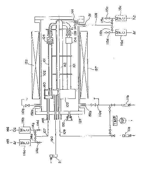
Fig. 5 shows an example of the piping system for
28
2~7~5
preventing -the pollution in the system at the time of this
gas change over. Numerals 116a, 116b and 118 respectively
correspond to the mass flow controller and the qas supply
piping having been shown in Fig. 1. Numeral 146 denotes the
supply line of the oxidation treatment atmosphere gas (for
example, 2), and 145 denotes the supply line of the purge
use gas (for example, Ar). Although the number of pipes for
effecting the oxida-tion treatment is different with the size
of the oxidation treatment furnace 137, they are constituted
with internal surface electrolysed SUS 316L tubes of about
3/8" or 1/2". Numerals 114a to 114d denote stop valves, and
make a monoblock valve formed by unification of 4 valves,
and in which dead space has been deceased as small as
possible. Numerals 807 and 808 denote spiral tubes for
preventing the mixing by the reverse diffusion of the
atmosphere components from the outlet, and numerals 809 and
810 denote needle valves. Numeral 107 denotes oxidation
treatment gas supply line, which is the line for supplying
gas to the oxidation treatment furnace 137 shown in Fig. 1.
Next, explanation will be given on the manipulation of
the piping system of Fig. 5.
At first, at the time of effecting the purge of the
inside of the oxidation furnace, valves llqb and 114c are
closed and 114a is opened to supply purge use gas to 107
from 145 via 116a and 118. At this time, the valve 114d is
opened, and the oxidation treatment atmosphere gas has been
purged to the exhaust line from 146 via 807 and 809.
After finishing the purge of the inside of the
oxidation furnace, nest, the mass flow controller 116b is
- 29 -
2~67~5
set to about 1/3 of the addition amount, and at the same
time of the closing of the valve 114d, 114b is opened. The
facts that the addition amount is set to 1/5 and reversely
act 114d and 114b simultaneously are the counter measure for
preventing the over shoot of the addition. It is needless to
say that the slow start mode of the mass flow controller may
be used.
By the way, as to the prevention of the over shoot, it
is possible to solve by dividing the addition to 3 times and
by carrying out it per 5 minutes to 10 minutes.
Also, it is desirable to let the outside of the
stainless steel tubes 101 not to be oxidized and polluted by
that, before supplying the oxidation treatment atmosphere
gas into the oxidation furnace chamber 102, the supply
pressure of the oxidation treatment atmosphere gas flowing
in the inside of the stainless steel tubes 101, other than
the inert gas flowing on the outside of the stainless steel
tubes 101 (inside of the oxidation treatment furnace 137) is
lowered to about 0.05 to 0.35 kg/cm2 to let the oxidation
treatment atmosphere gas not flow out to outside from the
support members 103 and 104 to prevent the outside of the
stainless steel tubes 101 is oxidized and polluted.
In the present embodiment, when the water amount in the
gas exhausted from the outlet has been measured, the value
of less than 10 ppb was stably attained during the oxidation
treatment. Especially, in the case, when inert gas was flown
from the side 151 at the time of reception of the unit, the
time for attaining to less than 10 ppb can be shortened,
also, in -the case when the piping system of Fig. 5 has been
- 30 -
2~7~
used, the value of less than 10 ppb could be continued to
preserve even in the time of the change over of the gas.
Further, as to the stainless steel tubes of 3/8" and
total length of 4 m obtained by use of the present
embodiment, after letting it stand still for about 1 week in
a clean room of the relative humidity of 50% at the
temperature of 23C, N2 gas was flown at the flow amount of
0.45 l/min, and the water amount contained in the Ar gas at
the outlet was measured with HYCOSMO (low temperature
optical dew point meter), it reduced to about 10 ppb after
passing the gas, and after 80 minutes, the level of the back
ground has become less than 0.12 ppb. That is, the stainless
steel tube obtained by use of the present embodiment has an
extremely excellent degassing characteristics of the
adsorbed gas, and as the result, it shows that the heating
oxidation treatment has been carried out in a super high
purity atmosphere having the content of water of less than
10 ppb.
As described above, by the present embodiment, super
high purity oxidation treatment atmosphere of the water
content of less than 10 ppb, which could not be realized in
the conventionally generally used metal oxidation treatment
apparatus and metal oxidation treatment method could be
realized at a low cost and with good production efficiency.
By the way, although in the above-described embodiment,
explanation has been given on the apparatus of Fig. 1 for
carrying out the inac~ivation treatmen-t of stainless steel
tubes, but it is clearly understood that it is applicable
not only to the inactivation treatment of stainless steel
20~g~
tubes, but also applicable to the inactivation treatment of
meals of another quality and shape such as, for example, the
piping parts such as the pipes, valves, etc. of Ni, Al,
etc., highly pure reduced pressure apparatus parts, etc.
Also, as the apparatus of the present embodiment, although
the one in which the oxidation treatment furnace 137 is a
transfers type has been shown, it may be a longitudinal
type.
Application Possibility in Industry
According to the present invention, an inactivated
state film of good ~uality can be formed on the internal
surface of stainless steel tubes, and the external surface
burning is prevented and recleaning is not necessary, and
cost down and productivity improvement have become possible
at the same time.
-- 3