Language selection

Search

Patent 2067109 Summary

Third-party information liability

Some of the information on this Web page has been provided by external sources. The Government of Canada is not responsible for the accuracy, reliability or currency of the information supplied by external sources. Users wishing to rely upon this information should consult directly with the source of the information. Content provided by external sources is not subject to official languages, privacy and accessibility requirements.

Claims and Abstract availability

Any discrepancies in the text and image of the Claims and Abstract are due to differing posting times. Text of the Claims and Abstract are posted:

  • At the time the application is open to public inspection;
  • At the time of issue of the patent (grant).
(12) Patent Application: (11) CA 2067109
(54) English Title: CARDBOARD PACKAGING FOR LIQUIDS
(54) French Title: EMBALLAGE EN CARTON POUR LIQUIDES
Status: Deemed Abandoned and Beyond the Period of Reinstatement - Pending Response to Notice of Disregarded Communication
Bibliographic Data
(51) International Patent Classification (IPC):
  • B65D 77/06 (2006.01)
  • B31B 50/74 (2017.01)
  • B65D 25/16 (2006.01)
  • B65D 25/40 (2006.01)
(72) Inventors :
  • HEUBERGER, ERICH (Germany)
  • KNORRICH, WOLF-DIETER (Germany)
  • DZIALLAS, JOACHIM W. (Germany)
  • PLESTER, GEORGE (Germany)
  • TROSKA, GEORG (Germany)
(73) Owners :
  • CARL EDELMANN GMBH
  • COCA-COLA COMPANY (THE)
(71) Applicants :
  • CARL EDELMANN GMBH (Germany)
  • COCA-COLA COMPANY (THE) (United States of America)
(74) Agent: MARKS & CLERK
(74) Associate agent:
(45) Issued:
(86) PCT Filing Date: 1991-08-16
(87) Open to Public Inspection: 1992-03-05
Examination requested: 1998-07-07
Availability of licence: N/A
Dedicated to the Public: N/A
(25) Language of filing: English

Patent Cooperation Treaty (PCT): Yes
(86) PCT Filing Number: PCT/EP1991/001563
(87) International Publication Number: EP1991001563
(85) National Entry: 1992-04-09

(30) Application Priority Data:
Application No. Country/Territory Date
P 40 26 562.5 (Germany) 1990-08-22

Abstracts

English Abstract


Abstract
There is provided a carboard packaging for liquids which
consists of a folding box, an inner bag arranged therein and
made from a plastic material, and of a withdrawal nozzle
which is accessible from the outside through a hole formed in
one wall of the folding box. The withdrawal nozzle comprises
a base plate which is welded or bonded in liquid tight
fashion to the bag at the inner side of said bag in a
weldless area thereof. The inner bag is only bonded to and
easily detachable from the folding box wall that includes the
hole for the withdrawal nozzle, but, apart from this, is not
bonded to the walls of the folding box. The withdrawal nozzle
is therefore secured against rotation, and the bag is
sufficiently fixed in the folding carton. In addition, it can
easily collapse during emptying, and the packaging can be
easily disassembled into its cardboard and plastic parts
after use (Fig. 2).


Claims

Note: Claims are shown in the official language in which they were submitted.


Claims
1. A cardboard packaging for liquids, consisting of a folding box
made from cardboard, an inner bag arranged therein and made from
a thermoplastic material, and of a withdrawal nozzle which is
accessible from the outside through a hole formed in one wall of
said folding box, characterized in that said withdrawal nozzle
(20) comprises a base plate (21) which is welded or bonded in
liquid-tight fashion to said inner bag (14) at the inner side of
said bag in a weldless area thereof, said inner bag (14) is
detachably bonded only in the area of the folding box wall (2)
that forms part of the folding box body and comprises said hole
(10), but, apart from this, is not bonded to the walls of the
folding box.
2. A packaging according to claim 1, characterized in that said
inner bag (14) consists of a part of a tube material whose clear
cross-section substantially fills that cross-section of the
inner space of said folding box that extends through the folding
box wall (2) provided with said hole (10), and which in the area
of the cutting edges (17, 18) is welded to welds (23) extending
parallel thereto, said welds (23) extending next to the two
folding box walls (12,13) that are bordering on said wall (2)
provided with said hole (10) and are not comprised by said
cross-section.
3. A packaging according to claim 1, characterized in that in
the area of the ends of said welds said inner bag (14)
respectively forms flat gores of which the gores adjacent said
withdrawal nozzle (20) are respectively clamped between folding
flaps (11b, 12) of said folding box which are folded onto one
another and form said other side walls of said folding box.
4. A packaging according to claim 2 or 3, characterized in that
said inner bag (14) consists of a weldlessly extruded tube
material.

5. A packaging according to claim 2 or 3, characterized in that
said inner bag (14) consists of a tube material made from a web-
like, longitudinally welded film material.
6. A packaging according to any of the preceding claims,
characterized in that said base plate (21) of said withdrawal
nozzle (20) comprises at least one extension (27) having a
rectilinear edge adjacent to one of said folding box walls
(1,3,11b) bordering on said wall (2) provided with said hole
(10).
7. A packaging according to any of the preceding claims,
characterized in that said folding box consists of a blank which
comprises four linearly successive sections (1,2,3,4) forming
the body of said folding box, and an adhesive tab (5) adjacent
thereto, said sections forming in the prebonded erected state of
said folding box four walls that surround a rectangular, sleeve-
like tubular cross-section, and said hole (10) being formed in
one (2) of said sections, and which on said sections (1,2,3,4)
also comprises folding flaps (11a,11b,12,13) which are provided
at both sides of said sections and which in the finish-bonded
state of said folding box are respectively positioned one upon
the other and form two further walls of said folding box.
8. A packaging according to claim 6 or 7, characterized in that
said (first) flaps (11b) provided on said section (2) forming
said wall with said hole (10), and said (third) flaps (11a)
provided on said section (4) forming the diametrically opposed
wall in the erected state of said folding box are relatively
short and respectively overlap half of the free cross-section of
said folding box at the most, said (second) flaps (12) provided
on one (1) of said sections (1,3) adjacent to said above-
mentioned sections (2,4) are smaller over the major part of
their length than said section (1) on which they are provided,
and said (fourth) flaps (13) on said remaining section (3) are
dimensioned such that they more or less fully overlap the clear

cross-section of said folding box, said second flaps (12) being
folded onto said third flaps (11a), said first flaps (11b) onto
said second flaps (12), and said fourth flaps (13) onto said
first flaps (11b) and bonded to said first, second and third
flaps (11a,11b,12).
9. A packaging according to claim 8, characterized in that a
gore of said inner bag (14) is respectively clamped between said
first and second flaps (11b,12).
10. A packaging according to claim 7,8 or 9, characterized in
that holes (19) through which the underlying inner bag (14) is
accessible from the outside during the erection of said folding
box blank are respectively formed in the folding flaps (11a)
fastened to said section (4) which is not adjacent to said
section (2) comprising said hole (10).
11. A prebonded blank for a cardboard packaging with an inner
bag made from a thermoplastic material, consisting of four
cardboard sections (1,2,3,4) which are arrranged in a row and
bonded to form a closed sleeve and which form said folding box
body and comprise folding flaps (11a,11b,12,13) laterally
extending therefrom, and with a film tube portion (14)
positioned in said blank and made from a thermoplastic material,
which film tube portion is open at both ends (17, 18) in the
area of said folding flaps (11a,11b,12,13) and detachably
connected to said blank by adhesive patches on at least some of
said folding flaps (11,11b).
12. A method of making a cardboard packaging according to claim
1, characterized by the following steps:
a) a developed folding box blank which comprises sections
(1,2,3,4) arranged one after the other in a row and forming the
body of a folding box and which includes flaps (11a,11b,12,13)
provided at both sides of each section has applied thereto a

pressure-sensitive or hot-melt adhesive over the entire surface
of a section (2) provided with a hole (10);
b) a film tube which is optionally provided with an opening and
consists of a thermoplastic material is placed in area contact
with the blank in a direction transverse to the row of said
sections (1,2,3,4), with said opening possibly coming to rest
above said hole (10), and the transverse dimension of said film
tube in the flat state being half as great as the sum of the
dimensions of said sections (1,2,3,4), measured in the direction
of the transverse dimension of said film tube, and said film
tube is bonded to said section (2) provided with said hole (10);
c) said film tube is cut off such that the length of the part
(14) to be bonded to said blank approximately corresponds to the
width of said blank measured over one section (3) and the flaps
(13) provided thereon;
d) said folding box blank is bent over and bonded at an edge (at
5) to obtain a flat blank;
e) said folding box blank is erected together with the film tube
portion (14) located therein;
f) unless it is already provided with an opening, said film tube
portion (14) is punched in the area of said hole (10);
g) a withdrawal nozzle (20) including a base plate (21) is
fastened from the inside in the area of said hole (10) to said
film tube portion (14) in a liquid-tight manner by welding or
bonding;
h) the open ends of said film tube portion (14) are sealed and
folded in; and
i) said flaps (11a,11b,12,13) of said folding box blank are bent
in and at least partly bonded to one another.

13. A method according to claim 12, characterized in that
in step a) pressure-sensitive or hot-melt adhesive patches (15,
19) are provided at discrete points on two respective flaps (12,
13) separated from each other by a flap (11b); in step b) the
film tube is also bonded to said blank at said adhesive patches
(15) contacted by it;
in step d) said film tube portion (14) is also bonded to said
blank at the remaining patches (19); and
in step h) the adhesive connections between said film tube
portion (14) and said folding box blank at said adhesive patches
(15, 19) are detached prior to the sealing of said film tube
portion (14).
14. A method of making a cardboard packaging with an inner bag
made from a thermoplastic material, characterized by the
following steps:
a) a developed folding-box blank which comprises sections
(1,2,3,4) arranged one after the other in a row and forming the
walls of a folding box body, and which includes folding flaps
(11a,11b,12,12) provided at both sides of each section is
provided with adhesive patches (15) on the folding flaps (11a,
11b) which are formed at two non-adjacent sections (2,4) of said
blank;
b) a film tube which is made from a thermoplastic material and
whose transverse dimension is half as great as the sum of the
dimensions of said sections (1,2,3,4), when measured in the
direction of the transverse dimension of said film tube, is
placed in its flat state on said blank in a direction transverse
to the row of said sections (1,2,3,4) and detachably bonded
thereto at the adhesive patches (15) covered by it;

c) said film tube is cut off such that the length of the portion
(14) bonded to said blank corresponds to about the width of said
blank, when measured over a section (3) and flaps (13) provided
thereon;
d) said folding box blank is folded over and bonded at an
adhesive tab (5) to form a flat, sleeve-like blank and also
bonded to said film tube portion (14) at the remaining adhesive
patches (15) coming thereby into contact with said film tube
portion (14);
e) said folding box blank is erected together with said film
tube portion (14) provided therein;
e) said film tube portion (14) is removed in the area of its one
cutting edge from said erected folding box blank by separation
from said adhesive patches (15) and sealed in the area of its
cutting edge (17) by welding;
g) the closed end of said film tube portion (14) is folded in
and said erected folding box blank is closed by bending over
said folding flaps (11a,11b,12,13) in said area and by bonding
the same to one another;
h) after filling of said film tube portion (14) through the open
other end, the latter is detached from said folding box blank by
removal from said adhesive patches (15) from said folding box
blank and sealed by means of welding in the area of the cutting
edge (18) which is located there;
i) said film tube portion (14) forming now an entirely closed
inner bag is also folded at its other end into said erected
folding box blank, and the remaining folding flaps
(11a,11b,12,13) are folded over and bonded to one another.

- 7 -
15. A substantially flat assembly for making a three-dimensional
cardboard package for liquids including a cardboard box blank
having fold lines defining walls of a cardboard box to be erected
and a plurality of connecting flaps, an inner bag of flexible
thermoplastic material, and a spout for withdrawing liquid from the
package, said spout extending through an aperture in a wall of the
box blank, said bag being securely bonded to the wall containing
said aperture, the improvement characterized by attachment means on
one or more of said flaps for detachably connecting the inner bag
thereto while the box blank is being erected to form the three-
dimensional package and thereafter when the box is fully erected
being capable of releasing the inner bag from the flaps to permit
the bag to collapse.
16. The assembly of claim 15 wherein said attachment means
comprises glue coated on portions of said flaps.
17. The assembly of claim 16 wherein said attachment means further
includes apertures in said flaps connectable to a vacuum source of
a box erecting machine.
18. The assembly of claim 15 wherein said attachment means
includes apertures in said flaps connectable to a vacuum source of
a box erecting machine.

- 8 -
19. A method of making a three-dimensional cardboard package for
liquids comprising the steps of:
providing a cardboard box blank having fold lines defining
walls of a cardboard box to be erected and a plurality of
connecting flaps;
providing an inner sleeve of flexible thermoplastic material
and a spout for withdrawing liquid from the package;
forming a hole in one wall of the cardboard blank;
inserting the spout through the hole and securely bonding the
inner bag portions surrounding the spout to said one wall;
detachably connecting other portions of the inner bag wall to
one or more of said flaps;
erecting the cardboard box blank into a three-dimensional box
by folding the walls and flaps about the foldlines; and
releasing the inner bag walls from the flap or flaps once the
box blank is fully erected into a three-dimensional box.
20. The method of claim 19 wherein said step of detachably
connecting is performing by applying glue to portions of said flap
or flaps.
21. The method of claim 20 wherein said step of detachably
connecting is further performed by applying suction through a hole
in the flap or flaps during erection of the box blank and stopping
said suction once the box blank is fully erected.

- 9 -
22. The method of claim 19 wherein said step of detachably
connecting by applying suction through a hole in the flap or flaps
during erection of the box blank and stopping said suction once the
box blank is fully erected.

Description

Note: Descriptions are shown in the official language in which they were submitted.


2~7~09
Cardboard Packaging for Liquids
This invention relates to a cardboard packaging which is used
for liquids and consists of a folding box, an inner container
arranged therein and made from a plastic material, and of a
withdrawal nozzle which is accessible from the outside through a
hole formed in one wall of the folding box. Such a cardboard
packaging is e.g. known from Garman patent application 38 02
793.
Packagings of this type are used as nonreturnable packagings and
intended as a substitute for bottles or containers made of
plastics, glass or sheet metal. Their main purpose consists in
facilitating their disposal after use. The folding box
guarantees the necessary stability, while the inner container
ensures a tight sealing o~ the liquid contained therein.
As for the packaging known from the above-mentioned publication,
the inner container consists of a flexible plastic bag which
after production must be insexted into the erected folding
carton. The delivery of the packaging in the finished state to
the filling company necessitates the transportation of empty
containers having a relatively large volume, which is not
economic. However, when the individual parts thereof are sent
separately - the outer carton may here be in a flat state, the
inner container must ~irst be inserted by the filling company
into the folding box to be erected at the ~illing plant.
Difficulties arising therefrom consist in-that when the inner
container is introduced into the folding box, the air contained
in this box must be removed. Moreover, the withdrawal nozzle
must be suitably positioned on the folding box in such a way
that it does not rotate during opening or closing i~ it is not
held by hand during these operations. As a result, the packaging
is relatively difficult to handle and uneconomic on the whole.

It is the object of the present invention to provide a cardboard
packaging of the above-mentioned type which can be produced
easily and handled in a space-saving way up ~o the filling
operation and, nevertheless, has the advantage that the inner
container can collapse in the folding carton during emptying so
as to prevent the contents thereof from coming into contact with
air prior to withdrawal, and it should here not be necessary to
hold the withdrawal nozzle separately during the screwing or
unscrewing of a screw cap or a withdrawal fitting.
This object is attained through the characterizing features of
claim 1. Advantageous developments of the invention are the
subject matter of the subclaims. A method of making such a
cardboard packaging is the subject matter of claim 8.
The invention, its features and advantages, as well as the
method of making and handling the cardboard packaging in the
production and filling processes shall now be explained in
greater detail with reference to an e~bodiment illustrated in
the drawings, in which
Fig. 1 shows a developed blank as a part of the cardboard
packaging;
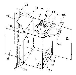
Fig. 2 a perspective view of the cardboard packaging with
an inner bag disposed therein, in the partly closed
state of the folding carton; and
Fig. 3 a detail of a vertical section through the packaging of
Fig. 2 - approximately actual size, and
Fig. 4 a developed blank of a cardboard packaging in accordance
with a simplified embodiment of the invention.
As shown in Fig. 1, the blank for the packaging of Fig. 2
substantially consists of four sec~ions 1, 2, 3 and 4 arranged
one after the other in the direction of arrow A, and of an

3 20671~
adhesive tab 5 bordering on one end thereof, with the individual
members being separated from one another by transversely
extending folding lines 6, 7, 8 and 9. In the erected state of
the folding box said four sections 1-4 form four complete walls
of the box~ One of the sections - in the present case section 2
- has a circular hole through which a withdrawal nozzle can
enter.
Two sections that are not adjacent - in ~he illustrated
embodiment sections 2 and 4 - are continued by lateral flaps lla
and llb, respectively, which have a width measured in a
diraction transverse to the direction o~ arrow A, i.e. in the
direction of arrow B, which is at the most half as great as the
length of section 1 and 3, respectively, measured in the
direction of arrow A. In the direction of arrow A flaps lla have
substantially the same dimensions as section ~, on which they
are mounted, while in the direction of arrow A flaps llb have
predominantly smaller dimensions than section 2, on which they
are mounted, as they are provided with cutouts. The reason for
this reduced size will be explained later.
One of the other sections - in the present embodiment section
1 - is laterally continued by flaps 12 which in the direction of
arrow B have a width corresponding approximately to the width of
sections 1-4, which is measured in the same direction. In tha
direction of arrow A, however, they are predominantly of a size
smaller than that of sections 1 and 3 on account of cutouts. The
reason for this reduced size shall also be explained later.
Section 3 is laterally continued by flaps 13 whose dimensions in
direction B are about the same as those of sections 2 and 4 in
direction B. In direction A flaps 13 have about the same
dimensions as sections 1 and 3.
AS shown in Fig. 2, the inner bag 14 consists of a portion of a
plastic tube which during the manufacture of the packaging is
placed in area contact with the blank in direction B and bonded
by means of a pressure-sensitive or hot-melt adhesive to section

4 2~7~9
2 over substantially the whole sur~ace thereof. When being
measured in direction A, the tube in its flat state has a width
which is about half the entire extension of sections 1-4 in
direction A. In this way the clear cross-section of the inner
bag 14 made from the tube portion corresponds approximately to
that of the folding carton in the erected state of the
packaging. In the area of hole 10 the tube may already be
provided with a corresponding opening before being placed onto
the blank. This opening rests above the hole 10 when the tube is
positioned on the blank.
The tube may be made from a flat film web welded in the
longitudinal direction. The weld, however, extends in an area
adjacent section 2, which is marked in Fig. 1 by a line 16 drawn
with two dashes and two dots. The longitudinal portion of the
tube which belongs to an individual blank is marked in Fig. 1 by
front and rear boundary lines 17 and 18, respectively.
During the manufacture of the packaging, and after the tube has
been placed on and fastened to ~he blank, the tube portion
intënded therefor is separated at ~he rear cutting line 18 from
the remaining tube material. Subsequently, the two outer
sections 1 and 4 are bent over onto the remaining blank and the
tube portion. Flaps lla provided on section 4 may optionally be
bonded to the tube portion with the aid of pressure-sensitive or
hot-melt adhesive patches 15, and the adhesive tab 5 is bonded
to section 1. In this state the inner bag 14 made ~rom the tube
portion is open at both cutting edges 17 and 18.
In this flat prebonded state the blank can be delivered in a
space-saving way to the filling company.
To finish the packaging, the prepared blank provided with the
open inner bag 14 is erected to obtalin a tubular body of a
rectangular cross-section with the aid o~ a conventional
erecting machine. The adhesive bond provided by the adhesive
patches 15 helps to erect the inner bag 14 in the blank, i. e .

2~7~9
the open inner bag 14 is automatically erected because it is
bonded to the blank.
Instead of or in addition to the use of adhesive patches 15,
flaps lla may alternatively be provided with holes 19 through
which the inner bag 14 is accessible from the outside to suction
applying means of an erecting machine whose suction means rest
on the inner bag 14 for erec~ing the folding box and thus erect
the folding box in a manner which is known per se. With this
alternative the adhesive patches 15 can be dispensed with.
Subsequently, a prepared withdrawal nozzle 20 is introduced from
one of the open sides of the inner bag 14 into the inner space
of the open packaging. Unless the inner bag 14 was not
previously provided with an opening in the area of the hole 10,
the inner bag 14 is circularly punched in the area of hole 10
prior to or simultaneously with the introduction of the
withdrawal nozzle 20.
The withdrawal nozzle 20 has a base plate 21 which is connected
in iiquid-tight fashion to the inner bag 14, e.g. with the aid
of a hot-melt adhesive or by direct welding, from the inside.
The withdrawal nozzle 20 may ~e a flexible nozzle which can be
pushed into the packaging in the manner of bellows, so tha,t it
does not protrude therefrom prior to use. Hence, to be able to
remove the nozzle from the packaging for making use of the same,
this nozzle is expediently provided with a handle 22.
After the introduction and mounting of the withdrawal nozzle 20
the optional adhesive bonds provided on the adhesive patches 15
betwisen the inner bag 14 and flaps lla are detached, and the
inner bag 14 is sealed along the cutting edges 17 and 18 by
weldirlg. The welds are designated with reference numeral 23 in
Fig. 2. It is necessary to detach the above-mentioned adhesive
bonds on the adhesive patches 15 (if they exist) in order to be
able to carry out the welding operation and, above all, to allow

6 2~7~9
the inner bag 14 to collapse in an unhindered way in the folding
carton when the contents thereof is discharged later.
After the welds have been made, the lateral portions of the
inner bag 14, which can be seen in Fig. 2 at the lower end of
the inner bag 14, are folded in and flaps lla are then the first
members that are bent in. Atten~ion must here be paid that the
respectively adjacent, folded gores of the inner bag 14 come to
rest entirely in the folding box. This state is shown in Fig. 2
at the right lower end of the packaging. Flaps 12 which have
smaller dimensions are then pivoted onto flaps lla. For this
purpose folding lines 24 (Fig. 1) are provided between section 1
and flaps 12. Attention must here be paid that the other gores
of the inner bag, of which one can be seen in Fig. 2 at the
right side, top, below flap llb, protrude from the folding box.
Flaps llb are then folded down together with the underlying
inner bag gores onto flaps 12, and the big flaps 13 are
subsequently folded as cover flaps onto the already folded,
partly overlapping flaps lla, 12 and llb.
. .
Since on account of their small dimensions flaps llb and 12 are
not as high as sections 1-4 which determine the height and depth
of the packaging, an adhesive can respectively be applied $o all
of the above-mentioned flaps llb, 12 and lla below the edge
portion of flaps 13. After the adhesive has been applied to
these exposed areas and the areas of the flaps 12 which are
adjacent the folding lines 24, flaps 13 are bent around folding
lines 25 (Fig. 1~ onto flaps lla,b and 12 and bonded thereto.
This results in a dimensionally stable folding carton whose
inner space is entirely sealed to the outside. There remains no
gap below flaps 13 through which foreign matter could penetrate
into the space between the inner bag and the folding carton.
The packaging can now be filled through the withdrawal nozzle.
After the latter has been closed and possibly punched into the

7 ~6~109
packaging, the hole 10 can be closed with an adhesive seal as a
warranty closure.
In the illustrated embodiment the withdrawal nozzle is
asymmetrically mounted, with hole 10 extending up to the
vicinity of one of the folding lines 26 that separate flaps llb
from section 2. Alternatively, it is also possible to provide
hole 10 at a somewhat greater distance from the folding line 26,
in particular in the middle of section 2. An eccentric mounting,
however, helps to empty the packaging completely.
The bonding between the inner bag 14 and section 2, and the
bonding between flange 21 and the inner bag 14 prevent the
withdrawal nozzle 20 from rotating when a screw cap or
connection fitting is screwed or unscrewed. Another safety
measure against rotation may consist in providing flange 21 of
the withdrawal nozzle with at least one lateral extension 27
(Fig. 2) which extends up to an edge of section 2 and is
supported on the subsequent flap llb and the adjacent carton
section 1 or 3. This extension 27 of flange 21 also helps to
position the withdrawal nozzle 20 when the latter is inserted
into and mounted onto the packaging.
The tube portion which is arranged in the folding c~rton and
constructed such that an inner bag 14 is obtained can be seen in
Fig. 3 showing a longitudinal section. In the illustrated
embodiment the tube por~ion comprises a longitudinal weld 16
which extends next to ona of sections 1 and 3. In the area of
section 2 in which hole 10 for the withdrawal nozzle 20 is
formed, the inner bag 14 is t~us without any welds. As a
consequence, the tight seal between flange 21 of the withdrawal
nozzle 20 and the material of the inner bag 14 is not impaired.
Furthermore, the folded portions (gores) of the inner bag 14 can
be seen in Fig. 3 at one side. As for the thicknesses of the
materials, FigO 3 is not true to scale. It is only to show how
the flaps are folded onto one another, with the inner bag gores

2~67~0~
that are adjacent the withdrawal nozzle 20 being enclosed
between the bent flaps llb and 12.
The reason for the last-mentioned measure shall now be
explained. The illustrated packaging is meant to be emptied in
an upside-down position, i.e. with the withdrawal nozzle facing
downwards, preferably with the aid of a suction device. Tests
have shown that certain amounts of liquid remain in the gores of
the inner bag and cannot be removed despite the application of a
suction force. When these gores that are at the bottom in the
use position of the packaging are enclosed between the above-
mentioned flaps llb and 12, the liquid volume that can be taken
up by them is negligibly small. At the same time, these gores
are fixed in position, so that they cannot hinder the emptying
process. A comparable positioning of the other gores is not
advisable, as the inner bag could otherwise not collapse during
the emptying process. To prevent an undesired absorption of
liquid by these gores, said last-mentioned gores may
respectively be sealed - during welding of the inner bag - by a
transverse weld which approximately extends at that place where
the respective gore protrudes from the semiclosed folding box
during manufacture of the packaging.
For the sake of clarity, threads or bayonet coupling portions on
the withdrawal nozzle 20 are not shown in the drawing because
they are not necessary for the explanation of the invention.
Moreover, none of the adhesive bonds is shown in Fig. 3 for
reasons of an improved depiction although, as has been
explained, an adhesive layer is provided between section 2 of
the folding box and the inner bag 14.
An important feature of the present invention is that the film
tube portiGn which later forms the inner bag is detachably
bonded to the flaps of the prebonded folding box blank by means
of individual adhesive patches which during the erection of the
blank serve to carry along the film ~ube portion which is in its
flat state and still unclosed, i.e. they help to erect the same.

206r~ L~9
Furthermore, it is importan~ ~hat during closing of the film
tube portion said adhesive patches are detached for forming an
inner bag. This feature of the invention can be employed
irrespective of the presence of a withdrawal nozzle with base
plate and irrespective of any bonding of the film tube portion
to the blank in the area of one of the sections forming the
folding box body.
Fig. 4 shows a developed blank with a film tube of such a
simplified embodiment. Unlike the embodiment illustrated in Fig.
1, film tube 14 of this embodiment is not bonded to section 2
pertaining to the folding box body, but to the adjacent flaps
llb on adhesive patches 15 and, after the other body sections 1
and 4 have been folded over, to flaps lla provided on section 4.
Such a prebonded, flat blank where adhesive tab 5 is bonded to
section 1 is characterized in that film tube portion 14 is only
bonded to flaps lla and llb by means of detachable adhesive
patches.
When this prebonded blank is handled by a packaging machine, it
is first of all erected. On account of the adhesive connections
provided on adhesive patches 15, the simultaneous erection of
the film tube portion positioned in the cardboard sleeve made
from the blank does here not present any difficulties.
Subsequently, film tube portion 14 is first removed at one side
of the erected blank from flaps lla and llb, e.g. the flaps
shown at the left side in Fig. 4, and sealed in the area of its
cutting edge 17 located there, whereupon the film tube portion
is folded into the folding box and the above-mentioned flaps
lla, llb, as well flaps 12 and 13 adjacent thereo are folded
over and bonded to one another. A gore of the inner bag which is
first only sealed at one side may be partly folded between the
f laps in a way comparable with that shown in the first
embodiment, and in accordance with Figs. 2 and 3. This feature,
however, can also be dispensed with so that the inner bag is
freely movable in the finished, completly closed packaging,

~1~671~
which particularly facilitates the separate disposal of carton
and inner bag after use of ~he packaging.
After the film tube portion and folding box have been closed at
one side, the ~ilm tube portion in the folding box can be filled
from the other side which is still open. Adhesive patches 15
which are still effective there and provided on flaps lla and
llb help to keep the film tube portion open. Subsequently, the
last-mentioned adhesive patches are also detached, the film tube
portion is closed and folded in for forming a completely closed
inner bag in the area of cutting edge 18, whereupon the folding
box is entirely closed at the side which is the right one in
Fig. 4 by folding over flaps lla, llb, 12 and 13 and by bonding
the same to one another.
It goes without saying that the last-mentioned technique ~ay
also be employed in the case of the first-mentioned embodiment
if there is no bonding of the inner bag to the folding box in
the area of the withdrawal nozzle.
Apart from this, the features of the~embodiment illustrated in
Fig. 4 correspond to those of Fig. 1; that is why they have been
provided with identical reference numerals in the drawing and
need here not be explained again.

Representative Drawing
A single figure which represents the drawing illustrating the invention.
Administrative Status

2024-08-01:As part of the Next Generation Patents (NGP) transition, the Canadian Patents Database (CPD) now contains a more detailed Event History, which replicates the Event Log of our new back-office solution.

Please note that "Inactive:" events refers to events no longer in use in our new back-office solution.

For a clearer understanding of the status of the application/patent presented on this page, the site Disclaimer , as well as the definitions for Patent , Event History , Maintenance Fee  and Payment History  should be consulted.

Event History

Description Date
Inactive: IPC deactivated 2021-11-13
Inactive: IPC assigned 2020-02-03
Inactive: IPC expired 2017-01-01
Inactive: Dead - Final fee not paid 2003-12-10
Application Not Reinstated by Deadline 2003-12-10
Deemed Abandoned - Failure to Respond to Maintenance Fee Notice 2003-08-18
Deemed Abandoned - Conditions for Grant Determined Not Compliant 2002-12-10
Notice of Allowance is Issued 2002-06-10
Letter Sent 2002-06-10
Inactive: Approved for allowance (AFA) 2002-05-31
Amendment Received - Voluntary Amendment 2002-02-25
Inactive: S.30(2) Rules - Examiner requisition 2001-11-20
Inactive: Correspondence - Formalities 1999-02-09
Inactive: Status info is complete as of Log entry date 1998-08-13
Inactive: Application prosecuted on TS as of Log entry date 1998-08-13
Inactive: RFE acknowledged - Prior art enquiry 1998-08-12
All Requirements for Examination Determined Compliant 1998-07-07
Request for Examination Requirements Determined Compliant 1998-07-07
Application Published (Open to Public Inspection) 1992-03-05

Abandonment History

Abandonment Date Reason Reinstatement Date
2003-08-18
2002-12-10

Maintenance Fee

The last payment was received on 2002-07-09

Note : If the full payment has not been received on or before the date indicated, a further fee may be required which may be one of the following

  • the reinstatement fee;
  • the late payment fee; or
  • additional fee to reverse deemed expiry.

Patent fees are adjusted on the 1st of January every year. The amounts above are the current amounts if received by December 31 of the current year.
Please refer to the CIPO Patent Fees web page to see all current fee amounts.

Fee History

Fee Type Anniversary Year Due Date Paid Date
MF (application, 6th anniv.) - standard 06 1997-08-18 1997-06-18
MF (application, 7th anniv.) - standard 07 1998-08-17 1998-07-07
Request for examination - standard 1998-07-07
MF (application, 8th anniv.) - standard 08 1999-08-16 1999-07-19
MF (application, 9th anniv.) - standard 09 2000-08-16 2000-08-08
MF (application, 10th anniv.) - standard 10 2001-08-16 2001-07-24
MF (application, 11th anniv.) - standard 11 2002-08-16 2002-07-09
Owners on Record

Note: Records showing the ownership history in alphabetical order.

Current Owners on Record
CARL EDELMANN GMBH
COCA-COLA COMPANY (THE)
Past Owners on Record
ERICH HEUBERGER
GEORG TROSKA
GEORGE PLESTER
JOACHIM W. DZIALLAS
WOLF-DIETER KNORRICH
Past Owners that do not appear in the "Owners on Record" listing will appear in other documentation within the application.
Documents

To view selected files, please enter reCAPTCHA code :


To view images, click a link in the Document Description column (Temporarily unavailable). To download the documents, select one or more checkboxes in the first column and then click the "Download Selected in PDF format (Zip Archive)" or the "Download Selected as Single PDF" button.

List of published and non-published patent-specific documents on the CPD .

If you have any difficulty accessing content, you can call the Client Service Centre at 1-866-997-1936 or send them an e-mail at CIPO Client Service Centre.

({010=All Documents, 020=As Filed, 030=As Open to Public Inspection, 040=At Issuance, 050=Examination, 060=Incoming Correspondence, 070=Miscellaneous, 080=Outgoing Correspondence, 090=Payment})


Document
Description 
Date
(yyyy-mm-dd) 
Number of pages   Size of Image (KB) 
Representative drawing 1999-09-29 1 15
Representative drawing 2002-06-02 1 11
Description 2002-02-24 14 639
Claims 2002-02-24 5 201
Drawings 2002-02-24 4 74
Claims 1993-11-19 9 301
Abstract 1993-11-19 1 25
Description 1993-11-19 10 434
Drawings 1993-11-19 4 70
Description 1998-09-23 14 653
Claims 1998-09-23 5 207
Reminder - Request for Examination 1998-04-19 1 117
Acknowledgement of Request for Examination 1998-08-11 1 177
Commissioner's Notice - Application Found Allowable 2002-06-09 1 165
Courtesy - Abandonment Letter (NOA) 2003-02-17 1 167
Courtesy - Abandonment Letter (Maintenance Fee) 2003-09-14 1 176
PCT 1992-04-08 29 1,083
Correspondence 1999-02-08 1 35
Fees 1998-07-06 1 54
Fees 2002-07-08 1 53
Fees 2001-07-23 1 55
Fees 1997-06-17 1 54
Fees 2000-08-07 1 51
Fees 1996-07-10 1 38
Fees 1995-07-13 1 40
Fees 1994-06-01 1 39
Fees 1993-06-28 1 31