Note: Descriptions are shown in the official language in which they were submitted.
2~67473
COMPOSITE E:LASTOMERIC SPRING
AND MOUNTING APPARATUS
.j .
BACKGROUND OF THE INVENTION
!Field of the Invention
;l
i This invention relates to composite el~stomeric springs and,
Imore particularly, to hollow composite elastomeric springs capable
; of providing a variable rate spring Ioad versus deflection curve
under certain load conditions.
Description of the Related Art
There are many applications in which it is desirable to
obtain a variable rate load versus deflection curve at or above
certain load leveli or deflections. Elastomeric springs often are
selected for such applications, because many elastomeric materials
~and particularly natural rubber provide this kind of spring curve
Iwhen sub~ected to uniaxial compre~sion. In addition to providing
¦variable rate spring cur~es, they also provide inherent vibration
¦damping. Ela~tomerlc ~prings typically take the form of solid
~blocks of elastomer or natural rubbex.
: When foxmed Lnto hollow or cylindrLcal ~hapes and sealed with
~respect to external pres~ure, elaitomeric spxing~ may yield
'additional spring properties due to the compression of the air
!
space wlthin the hollow elastomeric body. For example, hollow
elastomeric springs may provide spring properties generally
-- 1 --
20674~3
similar to air springs while pressurized internally, or they
may provide shock or load damping when selectively collapsible
in response to the discharge of internal air pressure through
a restricted orifice or the like. The spring effects thus
obtained provide additional flexibility with respect to the
variable rate spring curve obtained.
Hollow elastomeric springs, however~ tend to be unstable,
especially when formed with thin walls. To overcome this,
some springs of this construction include a helical coil
spring embedded within the wall of the elastomeric spring
body. The composite elastomeric spring thus obtained is of
generally tubular construction with opposed open ends. To
pressurize this spring internally, it is necessary to
establish continuous seals about both ends. ~epending upon
the construction of the load platens between which the spring
is compressed, the seals tend to leak or break down both as
the ends of the spring are deflected under load and as the
spring resumes its relaxed state a~ter compression.
SUMMARY OF THE INVENTION
Disclosed herein is a composite spring comprising: a
hollow elastomeric body and a coil spring embedded in the
body, the body having a closed annular wall extending
longitudinally between an open end and an at least partially
closed end wall; the coil spring having a helical portion
within the tubular wall extending continuously as a decreasing
diameter coil portion embedded in the at least partially
closed end wall. Also disclosed is a composite spring
comprising: a hollow elastomeric body having a closed annular
wall extending longitudinally between opposite body ends, at
least one of the body ends being open; a coil spring embedded
in the body and extending from a bearing end proximate to and
spaced ~rom the open body end to provide a sealing portion of
elastomeric material in the body adjacent the open body end;
an annular ring having a radial portion embedded in the
annular wall and an exterior portion extending from the radial
portion to the outside of the annular wall the radial portion
being positioned between the bearing end of the spring and the
20~7~73
sealing portion and; means for retaining the annular ring
relative to a planar surface to maintain the sealing portion
under a compressive force in fluid tight engagement with the
planar surface.
The present invention has been made in view of the
above circumstances and has as an aspect the provision of a
combined coil spring and elastomeric material to produce a
composite spring having the advantages of the elastic
properties o* both the coil spring and the elastomeric
material.
Another aspect of the present invention is to
provide a composite elastomeric spring in which one end is not
only closed but also is reinforced by the same spring coil
which acts as reinforcement for the side wall.
2A
2~7~73
i A further ob~ect of the present invention i8 to pro~ide
! springs of ~pecific geometries that display advantageous elastic
propertie~. For example, a spring may take a conical ~hape.
Another ob~ect of this invention i8 to provide a composite
~elastomeric spring having one open end ~nd one clo~ed end, and a
pas6age formed in the closed end which may be sealably clo~ed or
,opened to allow entry to and egres6 from the interior of the
Ispring.
, Another object of this invention i8 to provide an improved
ihold-down and ~ealed closure construction for a composite
ela~tomeric spring having one or both ends open and adapted to
accommodate the improved con~truction.
Additional ob~ects and advantages of the invention will be
~et forth in part in the description which follows and in part
will be obvious from the description, or may be learned by
~practice of the inven~ion. The ob~ects and advantages of the
jinvention may be reallzed and attained by means of the
instrume~t~lities and combinations p~rticularly pointed out in the
,lappended claims
! To achieve the ob~ects and in accordance with the purpo~e of
the invention, a5 embodied and broadly described herein, the
¦~pring of this invention compri~es a hollow elastomeric boiy and a
;!spring co~1 ~mbedded in the body. The body i~cludes at lea~t one
open end and a peripherally closed wall. In embodiments having a
circular configuxation with one clo~ed end, ths spring coil
includes both a decreasing diameter or ~piral coil ~egment
embedded in the closed end, and a helical 6pring segment embedded
1 20~7473
in the axlally extending wall portion of the elastomeric body to
resiliently reinforce the hollow body.
The objects of the present invention may also be accomplished
by a spring open at both ends and having any one of a variety of
,specific shapes. For example, the spring may take the form of the
frustums of two oppositely divergent cones ~oined together at
,their small ends. The spring may also take the form of two
,conical frustra attached at their small ends to the ends of an
intermediate cylindrical body portion.
! According to one presently preferred embodiment of this
invention, the wall includes a generally cyllndrical portion
between the open end and the closed end, and the coil spring
~includes at least one constant diameter helical coil segment
embedded in the cylindrical portion. According to another
presently preferred embodiment of thi~ invention, the wall
;includes a generally conical portion between the open end and the
closed end, and the coil spring correspondingly includes a conical
helix portion and at least one additional decreasing diameter
~spiral poxtion embedded in the 6mall e~d of the coni-cal portion.
~One closed end of the fipring may, but need not, include a passage
through which a suitable pressure fluid may be introduced into or
exhau~ted from the interior of the sprin~, and me~ns for sealably
clo~ing this passage.
According to 6till further embodime~t~ of the invention, the
body, whether of generally cylindrical or conical ~hape, includes
an annular shoulder projecting outwardly from an open end. A
hold-down ring may be partially embedded within or positionable in
-- 4 --
- 2067~73
overlying relation to the shoulder. When th~s ring is drawn
toward an underlying surface, it presses the shoulder against the
surface in a way which e6tablishes a continuous seal about the
open end. One pre~ently preferr~d embodiment of the hold~down
ring includes a stiffening lip that overlaps snd contains bulging
of the outer edge of the shoulder while it is pressed against the
surface. This lip also acts as a stop against further deflecti~n
of the shoulder. When embedded, and supported by the outermost
coil of one coil spring, the hold-down ring also acts as a locator
for molding the ela~tomeric body. In another hold-down ring
embodiment the outer stiffening lip extends upwards and does not
prevent the elsstomer in the shoulder from bulging. If not
embedded, the hold-down ring preferably includes a collsr that
engages and causes the shoulder to be deflected only along its
~inner edge, or ad~acent the outer surface of the wall.
In yet another embodiment, the annular ~houlder ~, 8 provided
with pro~ecting elastic ribs which extend about the periphery on
~the radlal face of the annular ~houlder. The ribs are compressed
between the shoulder and a closure member to assure an adequate
~ga~-tight seal between the elastomeric body ~nd the closure
~member.
To assure an aven and continuous seal between the ela6tomeric
body nnd the closure member a~ well as symmetrical load bearing
characteristics, the coil spring embedded within the body is
preferably mechanically flattened by abrading, for example, so
~ that the spring coil presents an e~sentially planar bearing
surface to at least the open end or Qnds of the spring.
-- S --
2067473
, Thus~ it will be appreciated that the pre~ent lnvention
provides a composite elastomeric spring in which the closed end is
capable of withstanding and tran~ferring ~upporting load forces
;directly to the spring walls. The spring effects obtained may or
'may not be supplemented by internal pressurization of the spring,
;idepending on the requiremen~6 of the ~pplication to which it i~
,put. In application~ where the height of the ~pring must be kept
¦to a minimum, for example~ ~he loss of resilient load bearing
support resulting from a reduction in spring height may be offset
~by forming the body of generally conical ~hape, and, if necessary,
increasing the wall thicknes~ 80 the coil spring is closer to the
iouter ~urface of the body wall.
BRIEF DESÇRIPTION OF THE DRAWINGS
The accompanying drawings, which are incorporated in and
constitute a part of this specification, illustrat0 embodiments of
the invention and, together with the description, ~erve to explain
th~ ob~ects, advantages and principles of the invention. In the
drawings,
Fig. 1 is a longitudinal section of one presently preferred
embodiment of the present invention;
Fig. 2 i~ a longitudinal section of a second presently
preferred embodiment of the present invention;
Fig. 3 is a partial longitudinal 8ection of a modified
con6tructlon of the Fig. 2 spring;
Fig. 4 is a paxtial longi~udinal ~ection of a modified
construction of the Fig. 1 hold-down ring;
- 20~7~73
Fig. 5 i8 a perspective view depicting the application of the
~,Flg. 1 spring to a load leveling system for a pickup truck, with
the system in an unloaded condition;
Fig. 6 i~ a per~pective view illustrating the Fig. 5 ~ystem
in a loaded condition;
Fig. 7 is a fragmentary cross-section illustrating an
alternate embodiment of the spring coil showing the addition of.a
closed second compres~ion member at the center of the ela~tomeric
body;
Fig. 8 is a fragmentary cros~-section illustrating the
elastomeric body having an open ~econd compres~ion member;
Fig. 9 is a fragmentary cro~s-section depicting a method for
attaching the hold-down means to the clo~ure plate;
Fig. 10 i8 a partial cro~s-section illustrating the
connection of Fig. 9 in greater detail;
Fig. 11 18 a partial cross-section illustrating a third
~embodiment of the connection between the hold-down meMns and the
~closure plate;
Fig. 12 18 a partial perspective ViQW showing the hold-down
ring provided with prongs to clamp the hold-down me~ns to the
closure pl~te;
Fig. 13 i8 a fragmentary cross-section of Fig. 12;
I Fig. 14 is a partial illustration showing the placement of
aperturas in the hold-down means 80 that the closure plate may be
ea~ily separated from the hold-down means;
Fig. 15 i~ a cro~ -sectional view of an aperture in the hold-
down means;
X067473
Fig. 16 Ls a cro~s-6ection of another embodiment of the hold-
~down device showing the attachment of a removal vice ring;
Fig. 17 i6 a top view of the apparatus illustrated in Fig.
16;
Fig. 18 is a perspective view illu~trating an alternate
design of the spring coil showing a coil having two flared cone-
like ends ~oined with a central cylindrical portion;
Fig. 19 is an isometric illustration ~howing a spring coil
having flared ends without a sentral cylindrical portion;
Fig. 20 is an isometric illustration of an embodiment of a
composite elastomeric ~pring of the invention in which an upper
cylindrical portion extends from a frusto-conical portion; and
Fig. 21 is an isometric illustration of an ~mbodiment of a
composite elastomeric ~pring of the invention having a non-
~ymmetrical physical configuration.
DETAILED DESCRTPTION OF THE PREFERRED EMBQDIMENTS
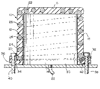
~ In Fig. 1, one presently preferred embodiment of the present
;jinventLon is shown to include a hollow elastomeric body, generally
designated by numeral 10, and a coil spring, generally designated
by numeral 12, embedded in body 10. Body 10 includes one open end
I 1~, one clo~ed end 16 and a wall 18 of generally circular
~transverse cro66 section. One end of coil spring 12 include~ a
constant di&meter, helical coil 20 embedded in wall 18 ad~acent
open end 1~. The other end of coil spring 12 includes a
decreasing diameter, generally spiral coil 22 embedded in clo6ed
end 16. In the illustrated embodiment, ~piral coil 22 has four
turns.
-- 8 --
.
20~747~
Wall 18 further includes a generally cylindrical portion
~between open end 14 and closed end 16. In this embodiment, coil
spring 12 includes three additional constant diameter of helical
windings 24, 26, and 28 interpo~ed between constant diameter coil
'20 and decreasing diameter coil 22. Like coil 20, these
additional coil windings are embedded in the cylindrical portion
if wall 18, as shown in Fig. 1.
As shown in Fig. 1, open end 14 may be pressed against and
sealed with respect to an underlying surface 30. In the
illustrated embodiment, thls i8 accompli~hed by a hold-down ring
~32 partially embedded in a shoulder 34 that pro~ects radially
.outwardly from open end 14. Ring 32 i8 supported along its inner
rim by a mechanically flattened end turn of coil 20. By suitably
positioning ring 32 with respect to coil 20, ring 32 may act as a
guide to en~ure proper location of the coil 12 when the ~pring 10
is molded. Ring 32 rigidly prevents the inner diameter of the
shoulder 34 from rolling inwardly when the interior of body 10 is
pressurized.
The flattened end turn of coil 20 i~ conventionally shaped by
forming or abrading. This feature of the spring i8 important from
the ~tandpoint of effecting a conversion of the inclined
orientation of the turns of a helix to an end bearing which is
substantially perpendicular to the axis of the helix.
Ring 32 also include~ a flanged lip 36. While preferably lip
36 overlaps the outer edge of shoulder 34 and constrains outward
bulging of shoulder 34 when ring 32 is drawn down against shoulder
34, as will be described presently, lip 36 may be upturned,
_ g _
2067~73
opposite to the orientation shown in Fig. 1 to allow uncon~trained
bulging of shoulder 34. Thi~ construction also tend~ to provide
desirable stiffness to ring 32. In the example illustrated in Fi.g
1, lip 36 also acts as a stop when it contacts surface 30, thereby
preventing further compression of shoulder 34. It will be
recognized that two rings of the same or generally ~imilar
construction as ring 32 could be used to retain and cause a seal
to be formed at both ends of an open ended tube.
Several retaining bolts are spaced apart at equal intervals
about shoulder 34, and when tightened, draw ring 32 down on~o
shoulder 34 and press it against surface 30. In Fig 1, only two
bolts are shown and are designated by numeral~ 38 and 40. These
bolts extend through openings formed by shoulder 34 and are
anchored by nuts (not shown) beneath surface 30. To facilitate the
establishment of a ~ight pressure seal between surface 30 ~nd
~houlder 34, the bottom ~urface of shoulder 34 includes one or
.more deformable annular steps 42 which, when pressed against
surface 30, form a continuous seal about the opening in open end
14.
A modified form of hold-down ring i~ illustrated in Fig. 4.
In this construction, the hold-down ring includes a solid collar
44 which registers with the outer surface of wall 18 ad~acent the
ba~e of shoulder 34. ~hen the Fig. 4 hold-down ring 1~ dr~wn down
toward surface 30, shoulder 34 is pressed against ~urface 30 and
forms a continuous seal. Vnlike the FigO 1 hold-down ring 32,
collar 44 concentrates the compressive force ex~rted on the upper
face of shoulder 34 along its inner edge. This concentration of
-- 10 --
,1 20~7~7~
.¦hold-down force tends to re~ist lifting of shoulder 34 when the
spring is pressurized internally. Unlike the Fig. 1 ~houlder 34,
the Fig. 4 6houlder 34 terminates at edge 46, exposLng part of
bolt 38. This allow~ unrestrained bulging of shoulder 34 between
the bolts 38, but traps the ela~tomer laterally. This prevents
.the inner diameter of ~houlder 34 from rolling inwardly when the
interior of body 10 is pressurized.
In the example illu~trated in Fig. 1, body 10 i6 elongated.
'In some applications of the pre~ent.invention, however, it may be
:de~irable to reduce the fipring height, whlle retainlng the
resilient 6pring effectfi obtained by having the decreasing
diameter or spiral coil embedded in the clofied end~ According to
a second preferred embodiment of this invention, the spring wall
may include a generally conical portion between ~he open end and
.the closed end, and the coil spring 12 may include at least one
additional decreasing diameter coil winding 22 embedded in the
conical portion. This embodiment is illu~trated in Fig. 2. In
Fig. 2, part~ corre~ponding to tho~e already illu~trated and
de~cribed with reference to Fig. 1 ~re not, for ~ake of brevity,
~further described herein, and ~re designat~d with the s~me
reierence numerals, primed.
As ~hown in Fig. 2, the outer wall 18' i8 generally conical
between open end 14' and clo~ed end 16'. In the embodiment
illustrated, coil spring 12~, a conically shaped helical coil,
includes:three decreafiing diameter coil winding~ 48, 50 and 52
embedded in wall 18~. The Fig. 2 ~pring may be secured by either
the Fig. 1 or Fig. 4 hold-down ring~. However, if the interior of
2067473
the composite ela~tomeric spring 10 is not pressurized, a hold-
!down may not be required.
The force versus the deflection curve of the conical spring
depicted in Fig. 2 may be controlled by var~ing the thickness and
or contour of wall 18~ as shown in Fig. 3. The force versus
deflection curve may also be changed by altering the location of
the ~pring coils 12 in relation to the inner and outer surfaces of
wall 18~. By positioning the spring coil winding~ 48, 50, 52, and
22~ near the outer surface of wall 18~, the force versus
deflection curve obtained tends to be ~teeper. That i8, the
spring 10 tend~ to be ~tiffer in response to axial deflection.
The ~pring curve obtained al80 may be controlled by
contouring the interior surface of wall 18~ as depicted by the
broken lines 54 and 56 in Fig. 3. By making the upper portion of
wall 18' thinner than the lower portion, as depicted by broken
line 54, the force ver~us deflection curve obtained tends to be
~teeper, or the spring tend~ to be ~tiffer. Conversely, by making
the lower poxtion oi wall 18' thinner than the upper portion, as
~depicted by broken line 56, the spring tends to be les~ ~tiff.
¦ As shown in Fig. 2, closed end lfi' includea a relief passage
S8. This pass~ge may be sealably clo~ed in those applications in
which the interior of the 6pring 10 i8 to be pre~surized. The
interior of spring 10 m~y be pressurized only when spring 10 is
mounted and sealed to an underlying ~uri~ce 30. In the example
lllu trated, relief pa86age 58 i~ sealed closed by a washer 60
held against the inside of closed end 16~ by a bolt 62 that
pro~ect upward through relief pa~age 58. The bolt 62 also
- 12 -
20~7~7~
,¦passes through an overlying load platen 64. A nut 66 i8 secured
to the pro~ecting exposed end of bolt 62 and, when t~ghtened onto
bolt 62, draw~ washer 60 snugly against the interior of clo~ed end
16', sealing relief passage 58. When it is desired to open relief
passage 58, bolt 62 is loosened. This allows the pressurized
fluid to p~s~ pa3t bolt 62 and through the relief passage 58.
As shown in Figs. S and 6, the Fig. 1 spring is used as a
load leveling suspension for the frame 68 of a pickup truck, for
~example. In this application, the Fig. 1 spring is pneumatically
inflated to provide load support and load leveling capability for
a load bed above or ad~acent two rear leaf springs that support a
rear axle 72. Only one leaf spring is shown and i~ indicated by
numeral 70. Unlike prior load leveling devices de~igned to stay
in contact with the load bed at all times, including both ~ounce
and rebound conditions, the application of the present invention
provides resilient load support only after the frame or load bed
~has bean loaded and deflected a predetermined amount with respect
to the cha~si~. Once this occurs, the load leveling suspension is
operative and may be used to pro~ide losd support and leveling
!capability in respon~e to the appllcation of additional weight.
,¦As will be appreciated, this application re9uires two spring
;assemblie~ one ad~acent each end of the rear axle 72, elther
ad~acent or overlying the two rear leaf 3prings, respectively.
For purposes of illustration, only the left side ~pring a~sembly
is illustrated and descrlbed in de~all, and parts corresponding to
those already illu~trated and described with reference to Fig. 1
are de~ignated by the same reference numerals, primed.
2067~73
Referring now in particular to Flgs. S and 6, the Fig. 1
~pring is mounted vertically between two spaced apart load bearing
supports with closed end 16 face up. The Fig. 1 spring may be
positioned between the leaf spring 70 and the frame 68. An upper
,support 74 pro~ects transversely from and is attached to frame 68.
A lower support 76 i8 secured by two U-bolts 78 and 80, and rests
upon leaf spring 70 in transverse relation to rear axle 72. In
the unloaded condition depicted in Fig. 5, a space is formed
~between the closed end 16 and support 74.
As the txuck is loaded to a certain weight, however, frame 68
is deflected downwardly until support 74 comes in contact with
,closed end 16, as depicted in Fig. 6. If additional weight is
~dded, the load bed 68 is further deflected causing the spring to
be compressed between it and the load support 76, or between the
load supports 74 and 76 as shown in Fig. 6. As the deflection
increa~es, the spring provides load bearlng support in addition to
that provided by the leaf springs, or ~he truck's other suspension
elements. Due to the variable spring rate provided by the spring
shown in Fig. 1, however, the suspension is stiffened before
bottoming out. This provides a more desirable ride than would
otherwise be obtained ~olely through the use of leaf springs.
To le~el frame 68, the Fig. 5 spring m~y be pres~urized by a
fluid introduced from an extcrnal pressure source (not shown), or
a source carried by the truck. If desired, the amount of pressura
fluid introduced into the interior of the spring Vi8 pressure line
82 may be controlled with respect to the amount of pressure fluid
introduced into the opposite spring assembly (not shown) to
- 14 -
2067~7~
establi~h a differential pres~ure-induced force on one side of the
truck or the other. Thi~ may be sufficient to level frame 68 ~o a
de~ired degree. It will ~e recogni~ed that this suspen~ion de~ign
may be u~ed in other types of vehicles to provide leveling or
raising or lowering of the body with respect to the chassis.
One ~pplication of the spring 10 shown in Fig. 2 is as a
progressive rate load bearing spring for a reclining chair, for
example. The ~pring lO shown in Fig. 2 i8 particularly desirable
for this and other applications in which space constraint~
;re~trict the height or the length of the ~pring. In such
applications, the decreasing diameter soil 22', when deflected by
a force applied along the center axis of the spring, may deflect
inwardly a suficient amount to provide acceptable resilient lo~d
bearing support. The Fig. 2 spring may or may not be internally
pressurized.
An advantage of both of the constructions depicted in Fig. 1
and Fig. 2, is that tha coil spring 10 and the elastomeric body
'may ba con~tructed 80 that they share to varyi~g degrees the load
japplied. In those applic~tion~ where the ~pring shown in Fig. 1
'is used to replace or as a replacement or substitute for air
~prings, for example, the coil spring m~y be sized 80 that it
'possesses a ~ufficient load be~ring c~pacity to remain active even
though tha ~ource of external pressure 18 lost or removed.
As shown in Fig. 7, the hollow elastomeric body 10 is
pxovided with a second compres~ion member 112 pro~ecting from the
interior surf~ce of ~he closed end 16. Fig. 7 depicts 2 seRled or
closed second compres~ion member 112, whereas Fig. 8 illustrates
- lS -
,1 206747g
an open second compression member 112 having an aperture 114
Itherein which allows the pressure fluid to escape when the
elastomeric body 10 i~ compre~ed. The aperture 114 may also be
provided to allow a shaft, such as in a hydraulic damper or
automotive strut, to pass therethrough. The second compression
'members 112 depicted in both Fig. 7 and Fig. 8 may be attached to
,closed end 16 with or without a decreasing diameter coil 22.
In the previou~ly described embodiments, the ~pring of the
present invention i~ clo~ed at the open end thereof by drawing the
ring 32 against the surface of a plate-like component of the
jdevice in whlch it i8 used, that is, the component ~hich defines
Ithe underlying surface ~uch as the load ~upport 76 in the
,exemplary application of Figs. S and 6. In Figs. 9-20, variations
of a self-contained ~pring embodiment of the invention are
! illustrated.
Fig. 9 illustrates an exemplary, self-contained embodiment of
the present invention in which a modified hold-down ring 132
,attaches to a closure plate 94 having a downwardly and outwardly
~flared peripheral edge 96. The hold--down ring 132 includes sn
llupper radial flange 132b, having spaced slots 132c for anchorage
.iin the molded elsstomeric body 10, and a depending peripheral
skirt portion 132d. The ~kirt portion 132d is formod with ~n
inwardly presented annular engagement led~e 92 to raceive and
engage the peripheral edge 96 of the closure plate 94.
Also i~ i~ to be noted from Fig. 10, that the shoulder 34,
defining the open end of the body 10, is provided with a radial
end face from which a pair of continuous annular ribs 90 project.
- 16 -
~ . 2067473
. By foxced pres~ing of the closure plate 94 into the ring 132, the
annul~r elastic ribs 90 deform ela~tically to securely engage the
.clo~ure plate 94 to create a gas-tight sQal around the hollow
elastomeric body 10.
To facilitate such assembly, the closure pl~te 94 preferably
includes spaced notches 98 in the peripheral edge 96. These
'notches 98 impart flexibili~y to the peripheral edge 96 of the .
;clo~ure plate 94 to facilitate the forced insertion of the plate
,94 into the hold-down ring 132. The same flexibility can not be
:achieved by adding gaps to the skirt portion 132d of the hold-down
,ring 132, because forcing the skirt portion 132d outward goes
against the inherent compression of hold-down ring 132 and natural
,curvature of skirt 132d.
Figs. 9, and 11 each depict slightly different constructions
principally of the skirt portions of the hold-down ring 132 and
iclo6ure plate 94. In Fig. 9, the engagement ledge 92 is provided
by an off-set edge portion struck inwardly from the skirt portion
, 132d of the hold-down ring 132. Xn Fig. 11, the ledge 92'' ln She
Iskirt portion 132d'' of the hold-down ring 132'' i8 an inwardly
.~bent seg~ent of the peripheral ~kirt edge.
~1 . ..
Flg. 12 depict~ another variatisn of the retention o~ the
! plate 94 and the hold-down ring. In thi~ embodiment, a~ shown in
,!cross-section in Fig. 13, the hold-down ring 132'~' i8 provided
with a plurality of peripherally ~paced prongs 100 inwardly
pro~ecting from the downwardly extending peripheral skirt portion
13~d'''. The prongs 100 extend inward far enough to engage the
peripheral edge 96 of the closure plate 94 to prevent separation
- 17 -
¦of the closure plate 94 from the hold-down rlng 132'''. To
provide greater flexihility in the skirt of the hold-down ring
,132~, the skirt 132d~ may be provided with spaced slits 102.
In each of the embodiments of Figs. 9-13, the ledge 92 or
'prong~ 100 engage the edge 96 of the plate 94 in a manner to
,establi~h the extent to which the sealing ribs 90 are compressed
after as6emb1y of the plate 94 and ring 132. Thus, by proper
dimensioning of the plate and the ring, the optimal sealing
,pressure of the ribs gO and plate 94 can be attained.
I Al~o it will be noted that the radial flange portions of the
rings 132 extend outwardly from the exterior of the shoulder 34 of
the elastomeric body 10. As a result of such outward exten~ion of
,the radial flange portion, an upwardly presented and exterior
,clamping surface i8 provided by which the plate 94 may be drawn
'into the ring 132, using appropriate tooling, and without need to
,compress or otherwise u~e the elastomeric body 10 during this
`a~embly procedure.
:j Fig~. 14 and lS depict the embodiment of Fig. 9 of the
lpresent invention with the added feature of aperture~ 104
. i
. extending through the ~kirt portion of hold-down ring 132. The
~pertures 104 allow ~ tool 106 to be pl~ced therein to di~place
!the closure plate 94 from the hold-down ring 132 80 that the
,~hollow elastomeric body 10 may be 6eparated from the clo~ure plat~
9~
In Figs. 16 and 17, a further al~ernative embodimen~ of the
invention i8 illu~trated. In thi6 embodiment, the hold-down ring
232, though again annular and extending~completely around the open
- 18 -
20~7~73
I
. end of the body 10, i8 generally rounded in radial cross section
to establish a relatively flat central portion 232a, having
apertures or slots 232b for anchorage in the elastomeric material
if the body, and rounded inner and outer edges 232c and 232d,
¦re~pectively. The closure plate 294, in this embodiment, is of
Idish-~haped configuration as a result of a rounded peripheral edge
¦294a, which in cross section, i8 a mirror image of the outer ed~e
.~2~2d on the ring 232. Thus, when the closur~ plate 294 is placed
¦in alignment with the ring 232, the plate and ring present an
outwardly convex conformation at the outer edges thereof. As a
result of this composite convex conformation, the closure plate
l294 and the ring 232 are effectively compressed toward one another
.by a b~nd clamp 236 80 that the annular rib~ 90 are sealed against
~the closurQ plate 294. Clofiure plate 294 and hold-down ring 232
can not over stre~s the annular ring 90 since the closure plate
294 and the hold-down ring 232 ~an not pass one another by clamp
, presRure .
Al60 in the embodiment of Figs. 16 and 17, the closure plate
;~294 is fixed, Euch as by spot welds 298, to a mounting bracket 300
having depressed, intersecting channels 302 with outwardly open
';slots 304 to receive mounting bolts 306. In addition, th~
channels 302 serve to receive and protect a fitt~ng 308 through
:-which pressurized fluid may be introduced through the closure
plate 294.
The spring of the present invention is ~daptable to different
configurations to accommodate specific and ~aried applications.
Flgs. 18, 19, and 20 illustrate alternate embodlments of the
-- 19 --
2~67473
hollow ~lastomeric body llOa and llOb, respectively. Fig. 18
~shows the body llOa having a central cylindrical portlon 120 and
two oppositely diverging frusto-conic~l portions 122, one ~uch
portion being attached to each end of the cylindrical portion 120.
Fig. 19 shows two frusto-conical portions 122b ~oined at the small
ends thereof without an intervening cylindrical portion 120. In
both cases, the conical portion~ 122a and 122b diverge toward the
opposite open ends of the body. In Fig. 20, a compo~ite spring
embodiment llOc is shown in which a cylindrical upper body portion
;120c extends from a generally flared, fru~to-conical bottom
portion 122c. Fig. 21 illustrate~ a composite elastomeric ~pring
llOd having a body 120d of a non-symm2trical configuration. The
spring embodiment i~ intended for applications in which a non-
;~ymmetricsl spring shape i8 needed to accommodated physical spaceconstraints and/or spring reaction to specific loading
requirements. Though not detailed in these figure~, all
,'embodiments may be open at opposite end~ and thus may be closed by
'any one of the closure plate constructions previou~ly described.
j The foregolng de6criptlon of preferred embodlments of the
¦invention has been presented for purposes of illustration and
!I description. It i6 not intended to be exhaustive or to limit the
~invention to the precise form disclosed, and modification~ and
variations are pos~lble in light of the above ~eachingR or may be
acquired from practice of the invention. The embodLments were
cho~en and described in order to explain the principles of the
invention ~nd its practic~l application to enabl~ one skilled in
the art to utilize the invention in various embodiments and with
- 20 -
1~ 20~7~7~ I
i various modifications as are ~uited to the particular use
. contemplated. It i8 intended that the scope of the invention be
deflned by the claim6 appended hereto, and thelr equl~lent6.
.
,1
.1
'I
. i , . ..
:
- 21 -