Note: Descriptions are shown in the official language in which they were submitted.
x-8570 -1-
2~7883
PORTABLE DRUG DELIVERY SYSTEM
The present invention relates to portable drug
delivery systems. Specifically, the present invention
relates to a belt-mounted hypodermic syringe discharge
unit with a corresponding belt-mounted holster.
Medical personnel are sometimes required to
administer subcutaneous injections to patients in the
field or outside the confines of a medically sterile
and temperature controlled clinical environment.
Veterinarians are often called upon to administer
injections to domestic livestock in barnyards,
corrals, out-buildings, or on the open range. In a
domestic livestock operation for example, ranchers or
veterinarians are responsible for administering drug
formulations to a large herd of livestock on a
periodic basis. Such periods between injections may
be as short as a a few days. In these situations it
is imperative that a drug delivery system provide a
means for inoculating a large number of animals in a
short amount of time. in order to effectively operate
in these environments, a drug delivery system must be
portable, reliable, convenient, and facilitate the
quick administration of drug dosages to as many
recipients as possible in minimal time.
In addition to ready portability and ease of
use, such systems must be designed to minimize the
risk of cross contamination between humans or animals.
The typical prior art system uses disposable pre-
filled drug cartridges with attached can~ulas
(needles). These disposable cartridges can be pre-
filled with a variet~ of liquid formulations including
antibiotics, steroids, vitamins, or formulations for
X-8570 -2-
2~6788~,
increasing milk or meat yield in domestic animals.
One particularly significant formulation is bovine
somatotropin (ssT) for use as an agent for increasing
milk production efficiency of dairy cows. While the
use of disposable cartridges significantly reduces the
problem of cross contamination, several problems exist
in the prior art. First, there is a tendency to~ard
excess breakage Gf cannulas from the cartridges.
Excess splitting of the cartridges is also present.
These problems arise due to the viscous character of
the formulations pre-filled in the cartridges. In
order to overcome the formulation viscosity, a great
deal of pressure must be applied to the syringe
plunger in order to administer the formulation. The
fact that some formulations must be refrigerated
between the point of manufacture and the point of use
exacerbates this problem.
In addition to the fact that some prior art
systems using disposable cartridges experience
breakage of the cartridge, another problem exists in
the disposal of spent (used) cartridges. The sharp
cannula attached to each disposable cartridge poses a
health and safety hazard not only to animals and
humans during the drug administration process, but
also a hazard to the general public once the spent
cartridges enter the stream of public waste disposal.
In addition, some state and federa~ regulations
re~uire that spent drug cartridges be destroyed in
order to prevent re-use of the cartridge. It is also
advantageous to separate the metallic cannula from the
typically plastic disposable cartridge in order that
the two components of different characteristics may be
disposed of separately. Prior art drug delivery
systems typically do not provide a means for conven-
iently and safely removing the cannula from the spent
X-8570 -3-
2~88~
disposable cartridge. Further, prior art systems
typically do not provide a means for disposing of the
cannula separate from the spent cartridge.
Prior art drug delivery systems experiencing
breakage of disposable cartridges, or not providing
ready means for destroying and disposing spent
cartridges, cannot satisfy the requirements for an
efficient and effective dxug delivery system. Thus,
an improved drug delivery system is needed.
The present invention provides an improved drug
delivery system comprising two basic components.
First, a gun style injection device used for holding
and administering a disposable pre-filled drug
cartridge is disclosed. Secondly, a holster device
used for receiving an end of the gun style injection
device and thereafter severing cannula from cartridge
and disposing of spent cannulas and cartridge~ is
disclosed. In addition, an improvement to the
cartridge and the injection device is disclosed.
The gun style injection device of the present
invention comprises a barrel, a handle, a hinged and
spring loaded squeeze lever, and a safety trigger.
The barrel, having a cylindrical bore, is open on one
side and adapted for receiving a disposable cartridge
with attached cannula inserted cannula end first into
a guide at the end of the barrel. The guide serves to
hold the disposable cartridge in place and to limit
axial movement of the cartridge within the barrel.
Within the cylindrical bore of the open side of the
barrel is a hinged and spring-loaded ejection plate
for forcibly ejecting a spent cartridge from the
barrel. The barrel housing also contains a slide lock
or cartridge ejection release means for holding the
ejection plate in place when the drug in the cartridge
X-8570
2~7~
is being administered. The cartridge ejection release
means also provides a means for releasing the
cartridge thereby allowing it to be forcibly ejected
from the barrel. A push rod slideably mounted within
the cylindrical bore of the barrel and used for
administering the drug within the cartridge is
operated from a retracted position while the drug
cartridge is being loaded to an extended position,
where one end of the push rod serves to force a
plunger down the extent of the drug cartridge, thereby
forcing the drug within to be expelled through the
cannula. The other end of the push rod is slideably
mounted on the squeeze lever. The push rod also
contains a small notch for receiving a stop tab member
attached to the safety trigger. The stop tab serves
to restrict movement of the push rod down the barrel
while the safety trigger is engaged.
The holster device of the present invention
comprises a leg protection panel to which a housing is
coupled for disposing of spent cartridges. The leg
protection panel is comprised of at least three
separate plastic sections, connected by flexible metal
sheets. The leg protection panel is covered with a
weather-proof plastic and formed in a convex shape.
The protection panel serves to prevent a user of the
system from inadvertently puncturing the user~s leg
while using the drug delivery system. The convex
shape of the panel increases the panel's support
strength and serves to better fit the rounded leg of a
user of the system. The leg protection panel is
further divided into at least three separate sections
thereby providing better longitudinal flexibility. On
one side of the protection panel are affixed two belt
loops and a leg strap allowing the holster to be hung
from the waist belt of a user. On the other side of
x-8570 ~5~ 2~7883
the protection panel, a support strap and snap is
provided for holding the gun style injection device
while not being used.
Coupled to a lower end of the leg protection
panel is a housing adapted for receiving the barrel of
the gun style injection device. This housing supports
a means for severing the cannula from a used cartridge
and disposing of both the cannula and cartridge in
separate containers. The holster device further
comprises a rotatable receptacle for receiving an end
of the injection device, a sharps container slidably
mounted to the housing, the sharps container including
a cannula (needle) severing means, a means for
supporting a spent cartridge containment bag, and a
toggle switch for reversing the operable direction of
the rotatable receptacle. The rotatable receptacle
comprises means for receiving the barrel of the gun
style injection device. The receptacle rotates within
a cylinder portion of the housing such that the gun
style injection de~ice may be inserted into the
receptacle and rotated in either direction. AS the gun
style injection device is rotated a first angular
portion within the receptacle, the cartridge located
in the gun style injection device is forcsd into a
blade edge fixedly mounted on the sharps container
which is installed within the housing thereby causing
the severance of the cannula from the cartridge. The
severed cannula thereafter drops straight through the
receptacle and cylinder portion into the sharps
container located directly beneath the receptacle and
cylinder portion. AS the gun style injection device
is rotated a second angular portion, a wedge member
fixedly mounted on said housing is brought into
contact with the cartridge ejection release means on
the gun style injection device thereby causing the
X-8s70 -6-
2~7883
ejection of the severed cartridge through an opening
in the side of the cylinder portion of the housing
into a spent cartridge containment bag supported by
said housing. The gun style injection device is
subsequently rotated to its original orientation and
removed ~rom the receptacle means. The sharps
container is slideably mounted on one end of the
cylinder portion with a locking mechanism included for
locking the sharps container into position. When
released, the sharps container can be removed from the
housing and sealed using a hinged cover with locking
mechanism coupled to the container.
m e housing further contains a support ridge
around said housing for holding and supporting a spent
cartridge containment bag. m e housing also contains
two rounded guide panels coupled to the housing for
guiding and shaping the spent cartridge containment
bag. m e guide panels also protect the containment
bag from being damaged by ejected cartridges.
m e cartridge design itself is improved in the
present invention in order to increase the performance
of the gun style injection device and the holster
cannula severing mechanism. A ridge is added to the
cartridge cylinder at the end joining the cannula.
m is ridge is adapted to engage an indentation in the
injection device ejection plate thereby locking the
cannula end of the cartridge solidly in place for more
efficient cutting by the holster severing mechanism.
In addition, ribs connecting the cannula to the
cartridge cylinder and supporting the cannula are
modified to add a wedging surface adapted to properly
align and position the holster severing blade for more
accurate cutting.
Two additional improvements to the injection
device are also described. First, an improvement to
x-8570 ~7 ~7~83
the injection device providing a means for adjusting
the dosage of drug delivered by the system. A set of
longitudinal grooves in the push rod of the injection
device cooperate with a tooth in a dosing knob thereby
restricting the movement of the push rod in one of
four different positions. The dosing knob may be
rotated to select the desired length of travel of the
push rod.
A second improvement to the ejection plate of
the injection device provides a means for allowing
cartridge rotation in one direction but limiting
rotation in the other direction. An angled tooth
extending through an opening in the ejection plate
serves to restrict rotation of a loaded cartridge in
one direction while allowing rotation in the opposite
direction.
X-8570 -8- 2 ~ 8 3
Figure 1 is a view showing the holster and gun
injection system.
Figure 2 is a side cut away view of the gun
style injection device.
Figure 3 is a side perspective view of the
holster with the g~n style in]ection device inserted
in the receptacle of the holster, a portion of the
Figure shown broken away.
Figure 4 i5 a top view of the holster showing
the angular movement of the gun style injection device
inserted therein (shown in phantom) and the subsequent
separation of the spent drug cartridge.
Figure 5 is a side cut away view of the holster
and gun style injection device showing the severing of
the cannula from the spent drug cartridge.
Figure 5A is a perspective view of the
combination of Figure 5 shown partially broken away.
Figure 5B is the same perspective view of the
combination of Figure 5A as shown in Figure 5A with
the gun style injection device rotated 90 from its
position in Figure 5A.
Figures 6A-C depict an improvement to the
cartridge and ejection plate of the injection device.
Figures 7A-D illustrate a further improvement to
the cartridge.
Figures 8A-C illustrate an alternative
improvement to the cartridge and holster severing
blade.
Figure 9A iS a top planer view of the sharps
container of the holster portion of holster and gun
injection system of Figure 1.
Figure 9B is a cross sectional view of the
elevational planer view of the sharps container of
Figure 9C.
x-8570 -9- 2~67883
Figure 10 illustrates an improvement to the
injection device providing a means for adjusting the
dosage of drug delivered by the system shown in
exploded view.
Figures 11A and 11B illustrate a further
improvement to the ejection plate of the injection
device providing a means allowing cartridge rotation
in one direction, but limiting rotation in the other
direction.
Figure 12 is a side perspective view of the gun
style injection device.
Figure 13 illustrates an alternative embodiment
of the gun style injection device with a means for
adjusting the dosage of drug positioned on the back
end of the push rod instead of positioned on the
barrel housing.
Figure 14 is a top perspective view of the
injection device showing the cartridge chamber.
Figure 15 is an exploded perspective view of the
rotated receptable and cyclindrical portions of the
holster of the system of Figure 1.
Figures 16A and 16B are top cross sectional
views of the assembled receptacle and cylindrical
portions of Figure 15 taken through a plane depicting
the selection of the direction of rotation of the
rotational receptacle.
Figure 17 shows the relationship of the cartridge
and needle to the severing means of the system as the
cartridge is rotated.
In the preferred embodiment, described and
illustrated in the drawings provided herein, the
present invention provides a readily portable, safe,
and efficient drug delivery system comprising a gun
X-8570 -10- 2~7883
style injection device, a holster device for severing
and disposing of spent drug cartridges, and an
improved drug cartridge. In the following description,
for purposes of explanation and not limitation,
specific mechanical structures, connections,
operation, etc. are set forth in order to provide a
thorough understanding of the present invention.
However, it will be apparent to one skilled in the art
that the present invention may be practiced in other
equivalent embodiments that depart from these specific
details. In other instances, detailed descriptions of
well-known aspects of prior art systems are omitted so
as to not obscure the description of the present
invention with unnecessary detail.
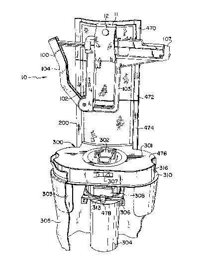
Referring to Figure 1, a preferred embodiment of
the portable drug delivery system of the present
invention designated generally 10 is illustrated. The
drug delivery system 10 is shown to comprise a gun
style injection device designated generally 100, a
holster including a leg protection panel designated
generally 200 and a housing and cartridge disposal
device designated generally 300. Injection device 100
is shown removably coupled to protection panel 200 by
a support strap 11. Support strap 11 is locked into
place with a snap 12. When snap 12 is unsnapped,
injection device 100 may be removed from pro~ection
panel 200~ On the other hand, housing and disposal
device 300 is permanently coupled to protection panel
200 at a lower end. On the reverse side of protection
panel 200, two belt loops are affixed thereto for the
purpose of supporting the protection panel 200 and
housing and disposal device 300 from the waist belt of
a user of the system. Plso affixed to protection panel
200, a leg strap 398 (Fig. 3) is provided to securely
x-8s70 -11- 2a67883
attach the protection panel 200 to the leg of the
user.
~ eferring now to Figures 2 and 12, the gun style
injection device 100 is depicted. As shown, injection
device 100 comprises a barrel designated generally 101
coupled to a handle 102 to which a hand guard 103 is
coupled. Similarly coupled to handle 102 is a hinged
and spring loaded lever 104. sarrel 101 further
comprises a cylindrical bore within which a push rod
106 is slideably disposed. Barrel 101 further
comprises a cartridge chamber 110 adapted for receiving
and positioning a cartridge coaxial with the bore of
barrel 101. Push rod 106 is slideably coupled to said
hinged lever 104 at narrowed region 111. Region 111 is
actually a ball-in-track joint. The track 170 on hinged
lever 104 allows the ball end of the push rod 106
coupled thereto to travel down the track as the hinged
lever 104 is squeezed. Hinged lever 104 moves push rod
106 between two positions: an extended position and a
relaxed position. As hinged lever 104 is moved
(squeezed) towards handle 102, push rod 106 is forced
through the cylindrical bore of barrel 101 and into a
cartridge positioned within cartridge chamber 110.
m is action serves to force the contents of the
cartridge through the cannula and into a recipient of
the injection. In this case, the hinged lever 104 and
push rod 106 are in the extended position. As pressure
is released on hinged lever 104, spring 112 urges
hinged lever 104 to the relaxed position shown in
Figure 2. The return of hinged lever 104 to its
relaxed position causes a corresponding retraction of
push rod 106 ~rom cartridge chamber 110 through the
bore of barrel 101. A stop tab 113 prevents push rod
106 from being fully retracted from the bore of barrel
101. Push rod 106 also contains a notch 114 for
~788~
X-8s70 -12-
receiving a corresponding trigger tab 451 coupled to
safety trigger 105. With the trigger tab 451 of safety
trigger 105 positioned within notch 11~ as shown in
Figure 2, push rod 106 is prevented from moving within
the bore of barrel 101, and correspondingly, hinged
lever 104 is prevented from moving towards handle 102.
This safety mechanism prevents the inadvertent
discharge of the contents of a drug cartridge. As
safety trigger 105 is depressed towards handle 102 into
a release position, safety trigger 105 pivots about
hinge 115 thereby causing the trigger tab 451 to be
retracted from notch 114. This action causes push rod
106 to be freely moveable within the bore of barrel
101. As safety trigger 105 is released, spring 116
urges safety trigger 105 back into the relaxed position
shown in Figure 2. When in relaxed position, safety
trigger 105 again positions trigger tab 451 within
notch 114 thereby preventing movement of push rod 106.
In an alternative embodiment, spring 112 and spring 116
may be combined into a single spring wherein one end of
the spring pro~ides the force necessary for the hinged
lever 104, and the other end of the spring provides the
force necessary for the safety trigger 105. Hand guard
103 is positioned in proximity to handle 102 in order
to protect the hand of a user while the injection
device 100 is being operated.
The foreword end of push rod 106 closest to
cartridge chamber 110 is terminated by a head 117
which is larger than the shaft of push rod 106 and
larger than the bore of barrel 101, as shown in Figure
12. This head 117 has a diameter slightly smaller
than the inside diameter of a cartridge placed in
cartridge chamber 110. A flat portion of head 117
(see Fig. 14) assures that head 117 clears cartridge
stop 131. Thus, head 117 retracts to a position
x-8570 -13- 2 ~ 8 ~
~ehind stop 131. The back end of push rod 106,
fastened to hinge lever 104 with a ball-in-track
joint, has a reduced diameter at 111 in order to be
slideably coupled with hinged lever 104 through a key
hole slot 172 at the bottom of track 17 0 . The bottom
of hinged lever 104 is attached at hinge 118 to handle
102 thereby allowing rotation of hinged lever 104
about the center of hinge 118. The back surface of
hinged lever 10~ is curved to fit the palm of a hand.
At the foreword end of barrel 101, a car~ridge guide
107 iS coupled to the barrel 101. The cartridge guide
107 contains an aperture 453 adapted for receiving the
cannula end of a drug cartridge with a sheath over the
cannula. Aperture 453 forms a cylindrical opening
with an interior dimension slightly larger than the
cannula end of a drug cartridge. AS a cartridge is
inserted in~o cartridge guide 107 and depressed into
an operating position within chamber 110, the cannula
end of the cartridge is, at the same time, raised to
meet the interior upper surface of cartridge guide
107. This action serves to properly position the
cannula end of a drug cartridge within chamber 110.
Cartridge guide 107 also serves to properly position a
cartridge relative to slot 119. The cannula is
severed from the cartridge through slot 119. A
holster device, described below, includes a cutting
blade element which is specially adapted and
positioned to pass through slot 119 thereby severing
the cannula from the cartridge. Cartridge guide 107
facilitates this process by rigidly holding the
cartridge and cannula in place while the severing
operation occurs.
An important element of injection device 100 is
ejection means 108. Ejection means 108 provides a
means for forcibly removing a spent cartridge with a
x-8570 -14-
2067883
severed cannula from chamber 110. Ejection means
designated generally 108 comprises an ejection plate
455 of a dimension to fit within chamber 110.
Ejection means 108 is coupled to barrel 101 at hinge
120. Thus coupled, ejection means 108 is free to
rotate about the center of hinge 120. This rotation
of ejection means 108 occurs between a cartridge
loading position shown in phantom, where one end 457
of said ejection plate 455 extends out of said chamber
such that a new cartridge may be loaded into chamber
110, and an operating position, where both ends of
said ejection plate 455 are positioned within said
chamber and a cartridge resting on said ejection plate
455 is positioned coaxial with the bore of barrel 101.
A spring 121, positioned underneath ejection means 108
as shown, serves to urge ejection means 108 in the
upward direction thereby forcibly removing a spent
cartridge from chamber 110 when the ejection means is
not locked in place by ejection release means 10g.
Once a spent cartridge has been ejected from chamber
110 by ejection means 108, ejection means 108 is in
the loading position and ready for the insertion of a
new cartridge. When the new cartridge is placed into
position on the plate of ejection means 108 and pushed
down into the operating position, the plate of
ejection means 108 serves to properly align the
cartridge in coaxial configuration with the bore of
barrel 101.
A cartridge is locked into an operating position
coaxial with the bore of barrel 101 using an ejection
release means 109. Ejection release means 109 is
slideably mounted on barrel 101 along push rod 106.
Ejection release means 109 is configured to slide in a
direction parallel to the movement of push rod 106
within the bore of barrel 101. The movement of
x-8570 -15- 2G~7883
ejection release means 109 operates b~ween two
positions: a cartridge lock position and a cartridge
release position. In the cartridge lock position, a
front edge 122 of ejection release mea-ns 109 makes
contact with an upper surface of ejection means 108.
n addition, edge 122 makes contact with a cartridge
loaded in chamber 110 and holds the cartridge 318 down
in the opexating position. Spring 124, compressed
between an intermediate wall 461 within barrel 101 and
circumferential tab 125 of release means 109, serves
to urge ejection re]ease means 109 in~o the cartridge
lo~k position by applying pressure to circumferential
tab 125. In the cartridge lock position, ejection
release means 109 overcomes the force being applied by
spring 121 to the underneath side of ejection means
108. A cartridge positioned in chamber 110 is thereby
held in an operating position (i.e. coaxial with the
bore of barrel 101) by release means 109. Ejection
release means 109 is moved to the cartridge release
position by sliding ejection release means 109
backwards in a direction away from chamber 110. m is
action is depicted in Figure 2 by the line and arrows
463 and with a portion of ejection release means 109
shown in phantom. AS ejection release means 109 is
moved to the cartridge release position, locking edge
122 is moved away from and ceases to make further
contact with a cartridge 318 in chamber 110. Once a
cartridge is free of locking edge 122, spring 121 is
then free to force ejection means 108 in the upward
direction thereby forcibly removing the cartridge from
chamber 110. The leading surface of locking edge 122
is angled such that a cartridge may be depressed into
the operating position without directly manipulating
ejection release means 109. m e wedge action of the
leading surface of locking edge 122 serves to
x-8570 -16- 2~67~83
temporarily displace ej ection release 109 into the
cartridge release position while a cartridge is
snapped into the operating position. Spring 124 then
operates to urge the ejection release 109 back into
5 the lock position thereby locking the cartridge into
an operating position within chamber 110. The push
rod 106 passes through the aperture formed by
circumf erential tab 125 helping to capture the
ejection release means 109 to the barrel 101.
An ejection support means 126 is fixedly
attached to the upper side of barrel 101. Ej ection
support means 126 serves to define a slot 123 between
a surface of ejection support means 126 and a surface
of ejection release means 109. Slot 123 is
15 particularly adapted for autc)matically activating
ejection release 109 by a wedge member affixed to the
holster device as described below. The holster wedge
member is positioned for insertion into slot 123 when
inj ection device 100 is rotated in the holster device
20 as described below. As the holster wedge member is
inserted into slot 123, ejection release means 109 is
forced backward into the cartridge release position
thereby causing the ej ection of a spent cartridge from
chamber 110. Ejection support means 126 serves to
25 assist the holster wedge member in forcing release
switch 109 to the cartridge release position.
Ejection release 109 is also provided with a small
rounded end 127 for manual operation of the switch.
B~ activation of ejection release means 109 either
30 automatically using a holster wedge member or manually
using rounded end 127, ejection release means 109
re~uires a force applied to move ej ection release
means 109 into the cartridge release position thereby
allowing a cartridge to be ejected from chamber 110.
35 When this force is released, ejection release means
2$~7~83
X-8s70 -17-
109 ls returned to the cartridge lock position by
virtue of the force applied by spring 124 .
With the exception of the spring components of
the gun style injection device 100, the entire device
may be manufactured of a plastic material. For
example, the injection device 100 may be molded of a
polypropylene or polycarbonate material. Techniques
for molding plastic in this fashion are well know to
those skilled in the art. The overall structural and
o reinforcing members of the injection device 100 are as
shown in the accompanying drawings. Thus, the gun
style injection device 100 of the present invention is
described.
Referring again to Figure 1, the protective
panel 200 and holster device 300 are shown. The leg
protection panel 200 is comprised of at least three
separate plastic sections, connected by flexible metal
sheets. The leg protection panel 200 is covered with
a weather proof plastic and formed in a convex shape.
The protection panel 200 serves to prevent a user of
the system from inadvertently puncturing the user's
leg while using the drug delivery system. The convex
shape of the panel 200 increases the panel~s support
strength and serves to better fit the rounded leg of a
user of the system. The leg protection panel 200 is
further divided into at least three separate but
coupled sections even numbers 470 through 474 thereby
providing better longitudinal flexibility. On one
side of the protection panel 200 are affixed two belt
loops allowing the holster 300 to be hung from the
waist belt of a user. On the other side of the
protection panel, a support strap 11 and snap 12 is
provided for holding the gun style injection device
while not being used. Also affixed to protection
panel 200, a thigh strap 39~ is provided to securely
x-8570 -18- 2067883
attach the protection panel 200 to the leg of the
user.
Holster 300 is shown to comprise a housing 301
affixed to leg protection panel 200 at a lower end of
5 section 474. Housing 301 includes a flat upper surface
476 in the center of which a recessed, rotatahle, gun
receptacle 302 is positioned. Referring now to Figure
15 for more details on the rotatable gun receptacle 302
is generally cylindrical in shape and is a molded part
o from plastic in the preferred embodiment. A channel
co~prising a plurality of rectangular portions shaped
to receive the cartridge containing end of the gun
passes through the center of the cylinder. The
combination rectangular channel comprises two opposing
15 side surfaces 1502 and 1504 separated by a third
rectangular surface 1506 which includes a slanted
interior bottom 1508 which supports the angled frame
280 shown in Figure 2. The cartridge-containing end of
the gun will slide easily into the multirectangular
channel of the receptacle 302 until the outside surface
of the handle guard 103 engages the flat surface of the
housing 301 of the holster. This is shown in Figure 3.
The cylindrical shape of the receptacle 302 is
formed by a number of parallel and spaced-apart
annular surfaces even numbers of 1512 through 1520.
Annular surface 1520 is the top surface in which the
rectangularly shaped channel is formed and surface
1512 is the bottom surface of the cylinder. These
annular surfaces are really rib like in structure and
provide support for the receptacle 302 without adding
a large amount of mass and adding weight to the
holster. The rectangular channel opens up to am~ient
atmosphere through a rectangular opening 1530 in a
side of the receptacle 3Q2. The opening 1530 extends
from the bottom surface 1512 to the top annular
2~7883
x-8570 -19-
surface 1520 except for a straight bridge member 1532
attached to the bottom of the plate 1512 across the
opening.
The receptacle 302 is attached to the housing
301 by a receptacle housing which is shown in Figure
15 separated into two halves 1540 and 1542. To
assemble ~he receptacle and the receptacle housing
with the housing 301, the two halves 1540 and 1542 are
brought together to encircle the receptacle 302. The
0 bottom annular sur~ace 1512 i~ captured by an annular
ridge 1544 in the bottom of halves 1540 and 1542 which
forms a completed circle when the two halves 1540 and
1542 are brought together. Similarly, annular ledge
1546 mates with an annular channel 1548 on the top
plate 1520 of the receptacle 302. Hence, when the two
halves of the receptacle housing 1540 and 1542 are
brought together to encircle the cylinder 302, the
cylinder 302 becomes captured between the bottom
circular ridge 1544 and the top circular ledge 1546 of
the receptacle housing formed from halves 1540 and
1542. The receptacle housing halves 1540 and 1542 are
adapted to be bolted to the bottom surface of the
housing 301. In so doing, the top surface of plate
1520 of the receptacle 302 becomes coplaner with the
surface 4~6 of the housing.
Each of the housing halves 1540 and 1542 have a
side rectangular opening 1550 and 1552, respectively.
The receptacle 302 is able to rotate within the
receptacle housing and the opening 1530 can be aligned
with either the opening 1550 or 1552.
Housing 301 further includes a side panel 316
coupled to said upper surface of housing 301. A
suppGrt rim 310 extending from said side panel 316 and
extending entirely around housing 301 provides a means
for supporting a cartridge disposal bag 305 used for
~7~
X-8s70 -20-
containing spent drug cartridges with cannulas havingbeen severed therefrom. The open end of cartridge
disposal bag 305 is large enough to slide over the top
of support rim 310 yet small enough to rest firmly on
support rim 310 without falling off. Housing 301
further includes guide plates 303 attached to said
side panels 316 and extending downwardly therefrom;
said guide plates 303 for guiding cartridge disposal
bags 305 over rim 310 and for properly shaping
cartridge disposal bag 305. The inner surface of
guide plates 303 further provide the benefit of
protecting cartridge disposal bag 305 from damage by
cartridges being ejected from within gun receptacle
302.
Referring now to Figs. 16A and B, a top cross
sectional view of the receptacle 302 assembled
together with the receptacle housing halves 1540 and
1542 through the plane containing the annular surface
1518 is shown. The circular outer perimeter of the
surface 1518 contains two 90 cut outs or slots 1602
and 1604. The slots are located on either side of the
rectangularly shaped channel in the center of the
receptacle 302.
A rotation direction select switch 307 is
attached to the housing halves 1540 and 1542 about a
pivot point 1608 and extends through an opening in
side panel 316. Rotation direction select switch 307
serves to select the rotation direction of cylinder
302. Rotation direction select switch 307 provides a
selection between one of two directions of movement:
clockwise or counter clockwise movement of rotatable
cylinder 302. By depressing one side of rotation
direction select switch 307, a pin (1610 or 1612) is
extended into slot 1602 or 1604, respectfully, thereby
restricting movement in one of two directions.
x-8570 -21- 20~7883
Because the slot is 90, the :receptacle can rotate
90~.
The lower ends of receptacle housing halves 1540
and 1542 form a sharps container slide mount 306 when
they are attached together. Sharps container slide
mount 306 is particularly adapted to receive and
support the upper rim 902 on upper opposite sides of
sharps container 304. Thus, sharps container 304 may
be slid free and removed from holster 300.
Sharps container 304 is designed to hold a
collection of spent and contaminated cannulas that
have been severed from used drug cartridges. Sharps
container 304 is illustrated in detail in Figures 9A
through 9C. As shown, a set of blades 312 ~i.e.
cannula severing means) are attached to the sharps
container 304. Sharps container 304 is manufactured
of a material suitable to prevent sharp cannulas from
piercing the container from within. A sturdy
polystyrene or polypropylene material of a suitable
thickness may be used for this purpose. Sharps
container 304 may be slid into sharps container slide
mount 306 and locked into place with sharps container
lock 313 attached to slide mount 306 at the opening.
See FIG. 1. A pin 478, attached to sharps container
lock switch 30B, is designed to extend downwardly into
an opening 314 (Fig. 9B) in the sharps container
thereby locking the sharps container into slide mount
306. When removal of sharps container 304 is
necessary, sharps container lock switch 308 is moved
in an upward direction thereby removing the lock pin
478 from opening 314 and freeing sharps container 304
for movement out of slide mount 306. A leaf spring
(not shown) is inserted at point 315 (Fig. 5) between
the sharps container 304 and the end of slide mount
306. The leaf spring urges sharps container 304 out
2~7~8~
x-~s70 -22-
of slide mount 306 when lock pin 478 is removed from
lock 313.
As depicted in Figure 5 and Figures 9B and 9C,
sharps container 304 further includes a sharps
container cover 311 attached to the sharps container
by a hinge thereby providing a means for swinging
cover 311 across the top and closing sharps container
304. Sharps container 304 and cover 311 further
include a means for locking the cover in place thereby
sealing the open end of sharps container 304. In the
preferred embodiment, the cover locking means
comprises a tab 351 fabricated to fit into receiving
means 371 thereby frictionally holding cover 311 over
the open end of sharps container 304. Notably, all of
the sharp points and cutting edges of the drug
delivery system of the present invention are contained
within sharps container 304 once the cover is closed.
Thus, by removing the sharps container 304 from the
holster, all dangerous elements of the system can be
isolated and safely controlled.
A partial barrier 910 extends across a partion
of the top of the cylindrical container portion of the
sharps container in order to prevent used cannula from
escaping from the container through the top. A
passage 912 is provided through the barrier 910 into
the cylindrical container portion to allow severed
cannula to be deposited therein.
Referring now to Figures 3, 4, 5, 5A, 5B and 5C
in particular, the holster and cartridge disposal
device 300 is shown with gun style injection device
100 inserted into gun receptacle 302. The action of
inserting injection device 100 into holster 300 occurs
once an operator of the device has co~pleted the
injection and delivery of the formula in the drug
cartridge installed in the injection device 100. It
X-8570 -23- 2~7883
is subsequently desired to sever the cannula from the
spent drug cartridge and to dispose of the cannula and
cartridge into separate compartments within holster
300. Injection device 100 and holster 300 comprise
cooperative means for performing these operations as
the following description will demonstrate.
The cooperative operation of the injection
device 100 and holster 300 occurs in two basic steps.
First, injection device 100 is inserted into holster
device 300 as shown in Figure 3. Secondly, injection
device loo is rotated in either direction depending on
the setting of the rotation direction select switch
307. This injection device rotation step is depicted
in Figures sA and sB. As the injection device is
rotated, two operations occur at two positions of
angular rotation. In the preferred embodiment, the
first angular position is 45 of rotation in either
direction from the insertion position of the lnjection
device. The second angular position in the preferred
embodiment is 90 of rotation in either direction from
the insertion position of the injection device. It
will be apparent to those skilled in the art that the
two operations described below at each angular
position of rotation may occur at angular positions
different from 45 and 90.
In the preferred embodiment during the first 45
of rotation of injection device 100 in either
direction, the cannula 319 is severed from the spent
drug cartridge by one of a set of blades 312 attached
to the sharps container 304 which is installed within
holster 300. This is shown schematically in FIG. 17
where the cartridge 318 and cannula 319 in solid lines
is in the initial position while the dotted lines
shows what happens when the gun and receptacle are
rotated 45. See also FIG. 4. During the second 45
X-8570 -~4- ~6~88.3
of rotation of injection device 100, the ejection
means of injection device 100 is activated by
cooperating components coupled to holster 300.
Specifically, a wedge member 309 attached to the
inside surface of each of the receptacle housing
halves 1540 and 1542 serves to activate the ejection
means of injection device 100 thereb~ causing the used
and severed cartridge to be forcibly ejected from
injection device 100 through opening 1530 in
o receptacle 302 and either opening 1550 or 1552 in
receptacle housing 15~0 or 1542, respectively, and
into cartridge disposal bag 305. Notably, the sharps
container 304 and cartridge disposal bag 305 provide
two separate containers for holding different portions
of the spent drug cartridge. The two portions of the
spent drug cartridge can therefore be disposed of
separately.
Referring now to Figure 4, a view of hols~er 300
from a vantage point above gun receptacle 302 is
shown. An outline of injection device 100 in dash and
dotted lines as inserted into the holster 300 is also
shown. The center of rotation 317 of the injection
device 100 is also indicated. Since the drug
cartridge 318 installed within injection device 100 is
slightly off center of center point 317, cartridge 318
changes position along an arcuate path when injection
device 100 is rotated as shown. By virtue of this
change in position of drug cartridge 318, the rotation
of injection device 100 moves the cartridge 318 into
one of two spaced apart cutting blades 312 depending
upon direction of rotation. As the injection device
100 completes 45 of rotation, the cutting blade 312
will have severed the cannula from the body of the
cartridge~ By the time injection device 100 has
completed 90 of rotation, the severed cartridge will
~-8570 -25- 2~7~8~
have moved into a position directly above blade 312
and ~he severed cannula will have dropped through an
opening between blades 312 and into sharps container
304. The rotation of injection device 100 thus
provides a means for severing a cannula from a drug
cartridge.
Referring now to Figure 5, 5A and ss, the
operation of the cartridge ejection means and the
severing of the cannula from the cartridge is
illustrated. Again in Figure 5, injection device 100
is shown inserted into gun receptacle 302 subsequent
to the delivery of the dosage of drug formulation from
drug cartridge 318. Ejection release means 109 and
ejection support means 126 are also shown. In
addition, edge 122 of ejection release means 109 is
shown holding drug cartridge 318 in the operating
position within injection device 100. Wedge member
309 is also shown in a position aligned with slot 123
between ejection release switch 109 and ejection
support means 126.
As injection device 100 is rotated the first 45
of rotation, cartridge 318 and cannula 319 are moved
into contact with cutting blade 312 as described
above. As rotation continues, cannula 319 is severed
from cartridge 318 and falls into sharps container
304. As rotation of injection device 100 continues
for the second 45 of rotation, the leading tip of
wedge member 309 begins entry into slot 123. As
rotation of the injection device 100 continues, wedge
member 309 separates ejection release means lOg from
ejection support means 126. Ejection release means
109 is thereby forced backward and away from cartridge
318. As this wedging action continues, edge 122 of
ejection release means 109 eventually ceases to make
contact with cartridge 318. In so doing, edge 122
X-8570 -26- 206~883
ceases to apply downward pressure on cartridge 318.
With downward pressure being released from cartridge
318, spring 121 on the under side of cartridge
ejection means 108 of injection device 100 is now free
to forcibly push severed cartridge 318 from the
chamber 110 of injection device 100. The sev~red drug
cartridge 318 then flips out of injection device 100
and into cartridge containment bag 305. This leaves
the cartridge chamber 110 of injection device 100 in
the loading configuration. AS injection device 100 is
rotated back to its initial starting position, wedge
member 309 is removed from slot 123 and ejection
release switch 109 returns to the forward (cartridge
lock) position. In this position, ejection release
109 is again positioned to receive and lock in a new
drug cartridge. Once the injection device 100 is
rotated back to the initial start position, the
injection device 100 may be removed from holster 300
and thereafter loaded with a new pre-filled drug
cartridge. The cycle of injecting, delivering and
disposing of a new cartridge may then be repeated.
The holster may be manufactured of a plastic or
metal material suitable for rugged operation and
outdoor operating environments. The preferred
embodiment is manufactured from a polycarbonate
material of a thickness suitable to provide a durable
and lightweight holster. The leg protection panel 200
and attached holster 300 are designed with belt loops
and a leg strap on the back side of leg protection
panel 200 in order to provide a means for hanging the
holster fonm the waist belt of a user of the system.
In this way, the drug delivery system disclosed herein
is a light-weight, highly portable and efficient
device.
X-8570 -27- 2~78~3
The cartridge design itself is improved in the
present invention in order to increase the performance
of the gun style injection device and the holster
cannula severing mechanism. Referring to Figure 6a,
an improvement to the cartridge and a corresponding
modification to the ejection plate of the gun style
injection device is illustrated. AS shown, a ridge
615 is added to the cartridge cylinder 610 at the end
joining the cannula 611. Ridge 615 is formed by
extending the cylindrical surface of the cylinder 610
at the cannula end thereby creating an annular
recessed region 480 in which cannula 6Ll is coupled to
an end of cylinder 610 by cannula support means 612.
Cannula support means 612 includes longitudinal ribs
482 for positioning and supporting cannula 611. Ridge
615 is adapted to engage an indentation 620 in the
injection device ejection means 108 thereby locking
the cannula end of the cartridge 610 solidly in place
for more efficient cutting by the blade 312 of the
holster severing mechanism. As the improved cartridge
is loaded into the injection device 100 as shown in
Figure 6B, ridge 615 engages indentation 620. When
the cartridge 610 is then depressed into the operating
position as shown in Figure 6C, the cartridge 610 is
locked into place by the cooperation of ridge 615 and
indentation 620 at the cannula end of the cartridge.
At the other end, ~he cartridge is locked into place
by the ejection release means 109. Since the
cartridge is firmly locked into place in the injection
device, the cannula severing operation performed by
the holster 300 is more efficient. There is less
slippage of the cartridge as the cartridge is forced
into blade 312 as described above. Further, the
locking of the cartridge using the ridge improvement
serves to more accurately position and align the
X-8570 -28- 2~8~
cartridge for cutting in a predictable location along
cannula support means 612. rrhe ridge 615 and
indentation 620 improvement also minimi~es a gun
jamming problem experienced in prior art cartridge
devices. ~n the manufacture of plastic cartridges,
sometimes residual material is left behind from the
molding process around the clrcumference of the rear
end (i.e. end opposite of cannula end) of the
cartridge. The residual material can sometimes act as
a catch when the ejection release 109 is activated to
eject a cartridge from the gun. If the rear end of
the cartridge is caught by the ejection release 109,
the cartridge is pulled rearward clear of cartridge
guide 107 causing the severed end of a cartridge to
flip out of chamber 110 before the rear end of the
cartridge. This action may cause the gun-style
injection device 100 to jam. Ridge 615 in cooperation
with indentation 620 serves to hold the severed end of
a cartridge solidly in chamber 110 thereby minimizing
the potential for a cartridge to jam the gun 100.
An additional improvement to the cartridge of
the present invention is depicted in Figure 7A. As
shown in Figure 7A, the ribs of cannula support means
615 are modified to provide a wedging surface 715
adapted to properly align and position the holster
severing blade 720 for more accurate cutting. Wedging
surface 715 is formed by varying the cut of each rib
to create an inclined edge as shown in Figures 7A-D.
As illustrated in the sequence of Figures 7B-D, the
wedge shape 717 of the edge of holster blade 720
cooperates with the cartridge wedging surface 715 to
urge the cartridge 710 slightly upward as shown by
arrow 716 in Figure 7C as the cartridge 710 is forced
into blade 720 in the manner described above. This
slight movement of cartridge 710 serves to properly
X-8570 -29- 2
align the cartridge relative to blade 720 just prior
to the severing of the cannu]a depicted in Figure 7D.
Referring now to Figures 8A- C, an alternative
embodiment of the improvement to the cartridge of the
present invention is illustrated. In this alternative
embodiment, an improvement to the cartridge and a
corresponding modification to the severing blade of
the holster device is made. AS shown, a ridge 815 is
added to the cartridge cylinder 810 at the end joining
the cannula 811. Ridge 815 may be formulated in a
manner similar to the ridge 615 described above and
illustrated in Figures 6A- C . Referring still to
Figure 8A, a wedging surface 817 is formed on blade
820. A method for forming a blade in the shape shown
in Figures 8A-C will be apparent to those skilled in
the art. This blade wedging surface cooperates with
ridge 815 to urge cartridge 810 in an upward direction
as shown by arrow 816 as cartridge 810 iS forced into
blade 820 during the cannula severing operation
20 described above. This slight upward movement of
cartridge 810 serves to properly align the cartridge
810 relative to blade 820 just prior to the severing
of the cannula depicted in Figure 8C.
Two additional improvements to the injection
device are also described herein. First, an
improvement to the injection device provides a means
for adjusting the dosage of drug delivered by the
system. A second improvement to the ejection plate of
the injection device provides a means for allowing
cartridge rotation in one direction only, thereby
facilitating removal of the cannula cap and proper
positioning of the angled cannula tip.
Referring to Figure 10, a furthex improvement to
the injection device 100 provides a means for
adjusting the dosage of drug delivered by the present
2~7~
X-8570 -30-
invention. A collar 415 of dosing knob 413 iscaptured by two notches 416 in each half 405 of the
proximal or handle end of injection device barrel
housing 101 as the barrel 101 is assembled. Dosing
knob 413 is free to rotate within barrel 101. Dosing
knob 413 is formed with a cylindrical cavity in which
push rod 406 may be slideably inserted. A set of
longitudinal grooves 417 in push rod 406 cooperate
with a tooth 414 positioned in the interior cavity of
dosing knob 413. A lateral groove 411 is cut at a
particular location in push rod 406 such that tooth
414 is positioned in lateral groove 411 when push rod
406 is in the relaxed position. With tooth 414
positioned in lateral groove 411, dosing knob 413 is
free to rotate 360 around push rod 406. By allowing
this rotation of dosing knob 413, the user of the
injection device is able to select one of four
different dosing positions corresponding to the four
longitudinal grooves 417 in push rod 406. At each of
the four positions, tooth 414 is aligned with one of
the longitudinal grooves 417. Once tooth 414 is
aligned with one of the longitudinal grooves 417, push
rod 406 becomes free to travel into the barrel housing
101 through dosing knob 413 until tooth 414 makes
2s contact with a stop member 410 positioned within and
perpendicular to longitudinal groove 417. The push
rod 406 travel distance between lateral groove 411 and
stop member 410 corresponds to the amount of drug
forced out of the cartridge by the push rod 406. In
each of the four longitudinal grooves 417, a stop
member 410 is positioned at a different distance from
lateral groove 411. Thus, by rotating dosing knob 413
located on the barrel housing 101 and selecting one of
the four different longitudinal grooves 417, a user of
x-8570 -31- 2 0 ~ 3
the injection device may select one of four different
dosage levels delivered by the injection device.
In an alternative embodiment, an injection
device designated 494, as illustrated in Figure 13,
provides a dosing means 490 coupled to a push rod 493.
The dosing means is used to rotate the push rod
thereby enabling the use of one of two channels 491 or
492 cut into the push rod. The channels are of two
different lengths thereby limiting the travel of the
push rod to two different positions. These two
positions correspond to two different drug dosages
delivered by the gun.
Referring now to Figures 11A and 11s, an
improvement to the ejection plate 420 of injection
15 device 100 pro~ides a ratchet means for allowing
cartridge rotation in one direction, but limiting
rotation in the other direction. By limiting rotation
in one direction, the cartridge becomes securely fixed
in position thereby facilitating removal of a cap
20 covering the cannula. By allowing rotation in the
opposite direction, the cartridge becomes rotatable
for proper alignment of the angled tip of the cannula.
Referring again to Figures 11A and 11s, and
Figure 14, ejection means 420 is shown. An angled
25 tooth 421 iS shown extending through an opening 423 in
the ejection means 420. Spring 422 urges tooth 421
upward into opening ~23, but allows tooth 421 to be
depressed downward to a point where the upper edge of
tooth 421 iS flush with the upper surface of ejection
means 420. Tooth 421 iS positioned in ejection means
420 at a location corresponding to the position of the
longitudinal ribs 482 of the cannula support means 612
of a cartridge resting on the upper surface of
ejection means 420. The longitudinal ribs 482 are
35 shown in Figure 6A. Tooth 421 is angled to a point
x^8s70 -32- 2~78~
edge designed to fit between each of the longitudinal
ribs 482 of the cannula support means 612. As the
cartridge is rotated in one direction, each rib
strikes the angled surface of tooth 421 thereby
forcing tooth 421 downward by the wedge action of the
angled surface. As each rib rotates past tooth 421,
spring 422 causes tooth 421 to return to its full
upward position between ribs until the next rib causes
the downward force on the angled surface. Thus, the
angled surface of tooth 421 allows rotation of the
cartridge. However, rotation in the opposite
direction is prevented, since an angled sllrface is
present on only one side of tooth 421. Thus, a rib
rotating in the opposite direction cannot cause
downward pressure on tooth 421. Tooth 421 therefore
remains in place thereby preventing opposite rotation
of the cartridge.
Thu~, a belt worn, drug delivery system used for
delivering a dosage of formulation from a pre-filled
drug cartridge and thereafter severing and disposing
of used drug cartridges is disclosed.
Although this invention has been shown in
relation to particular embodiments, it should not be
considered so limited. Rather, it is limited only by
the appended claims.