Note: Descriptions are shown in the official language in which they were submitted.
2~67894
The present invention relates to a hanger for suspending
ob~ects from poles.
BACKaRO WD OF THE INVENTION
Leveraged hangers for suspending objects from poles are
known as i3 evidenced by Canadian Industrial Design
Registration number 68561. Canadian Industrial Design
Registration number 68561 di~closes two opposed pole engaging
gripping members in spaaed relation. A connecting member
extends between the gripping member~ and a leverage bar extends
from the connecting member. No fasteners need be used to
attach the leveraged hanger to a pole. The gripping members
of the hanger are maintained in engagement with the pole by the
leveraged force exerted by the weight of an object attached to
the leverage bar. J
,~
This hanger configuration provides a number of advantage~.
One advantage is that installation is simplified as there are
no fasteners or brackets involved. Installation takes a matter
of seconds as the connecting member need only be positioned
transversely against a pole and then rotated until the gripping
members engage the pole. A second advantage is that the
installation does not damage or in any way scar the pole.
It has been found, however, that there is one substantial
drawback to the use of leveraged hangers in regions which
experience strong winds. Strong winds aan overcome the
leverage force exerted by the object upon the leverage bar,
thereby disengaging the hanger from the pole. When this
happens the object falls to the base of the pole potentially
causing damage to the object suspended from the hanger or
injury to persons below.
SUMMARY OF THE INVENTION
What is required is a means for making leveraged hangers
l-a~ auaceptible to diaplacement by atrcng winda.
,
,
, , ' .
2~7894
According to the present invention there is provided a
hanger for suspending objects from poleæ which is comprised of
a first gripping member adapted to conform to the exterior
profile of and extend approximately half way around a perimeter
of a pole and a second gripping member adapted to conform to
the exterior profile of and extend approximately half way
around a perimeter of a pole. The second gripping member is
opposed to and in spaced relation to the first gripping member.
A connecting member extends between the first gripping member
and the second gripping member. The connecting member
maintains the gripping members in opposed spaced relation. The
distance between the gripping members is greater than the
diameter of the pole such that the gripping members are brought
into gripping contact with the pole by positioning the
connecting member transversely and pivoting the connecting
member about a transverse axi~ until the gripping members
engage the perimeter of the pole. A leverage bar i~ provided
having a first end extending outwardly at an angle from the
connecting member and a second end. Means is positioned at the
second end of the leveraged bar for securing an object, such
that the object exerts a force upon the leveraged bar to
maintain the gripping members in engagement with the perimeter
of the pole. Locking means are provided consisting of a
movable brace having a first end movably secured to the
leverage bar and a second end having a pole engaging member.
The moveable brace is moveable along the leveraged bar between
a locking position and a mounting position. In the locking
position the pole engaging member engages the pole in
opposition to the first gripping member thereby preventing a
strong wind from rotating the connecting member about the
transverse axis to disengage the gripping members. In the
mounting position the movable brace is spaced from the pole.
Means i~ provided to secure the movable brace in a preselected
position.
The presence of the brace prevents a strong wind from
overcoming the leveraged force exerted by the weight of the
.
. .:
~
' " ' ' '.:: ' ~ ': '
,,
.
.
2~)~789~ `
suspended object. Although beneficial results may be obtained
through the use of the hanger as described, there are other
problems potentially caused by strong winds other than merely
displacing the hanger. A sign hung securely to a hanger can
be destroyed by strong winds. In addition the torque applied
to the hanger by strong winds buffeting the sign can be
significant. Even more beneficial results may, therefore, be
obtained when the object suspended is a sign by having the
means positioned at the second end of the leveraged bar for
securing the sign include a hinge biased by a spring into a
preselected position such that winds strong enough to overcome
the biasing force of the spring cause the sign to pivot about
the hinge in the manner of a weather vane.
BRIEF DE8CRIPTION OF T~E DRAWING8
These and other features of the invention will become more
apparent from the following description in which reference is
made to the appended drawings, wherein:
FIaURE 1 iB a perspective view of a leveraged hanger
constructed in accordance with the teachings of the present
invention.
FIGURE 2 is a rear elevation view of the hanger as
illustrated in FIGVRE 1.
FIGURE 3 iB a front elevation view of the hanger as
illustrated in FIGURE 1.
DETAILED_DE8CRIPTION OF THE PREFERRED EMBODIMENT
The preferred embodiment, a hanger for suspending objects
from poles generally identified by reference numeral 10, will
now be described with reference to FIGURE8 1 through 3.
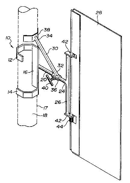
Referring to FIGURES 1 through 3, hanger 10 consists of
a first gripping member 12 and a second gripping member 14.
Both gripping members 12 and 14 are adapted to conform to an
exterior profile of and extend approximately half way around
a perimeter 17 of a pole 18. The term 'iexterior profile" is
intended to refer to the shape of pole 18, which may be
, ' ' ' :
. ': ' -
.. , ,, ~ .. .
.:. . . . , - : . ' . , .. -
- - - ~ . - - -
:- :. .. . .. .
206789~
circular, s~uare or in the form of a polygon. Second gripping
member 14 is opposed to and in spaced relation to first
gripping member 12. A connecting member 16 extends between
first gripping member 12 and second gripping member 14.
Connecting member 16 maintains gripping members 12 and 14 in
desired oppo~ed spaced relation. The distance between gripping
members 12 and 14 must be greater than the diameter of pole 18
to permit proper mounting as will hereinafter be further
described. A leverage bar 20 is provided having a first end
22 and a sècond end 24. First end 22 extends outwardly at an
angle from connecting member 16. In the illustrated embodiment
the angle is approximately 90 degrees. A mounting bracket 26
iB po~itioned at second end 24 of leveraged bar 20 as means for
securing an object; in the illustrated embodiment the object
is sign 28. The means for locking hanger 10 to pole 18 consist
of a movable brace 30 having a first end 32 and a second end
34. First end 32 is a sleeve 36 movably secured to leverage
bar 20, such that sleeve 36 slides back and forth along
leverage bar 20. Second end 34 has a pole engaging member 38.
Moveable brace 30 is moveable along leveraged bar 20 between
a locking position and a mounting position. In the locking
position, pole engaging member 38 engages pole 18 slightly
above and in opposition to first gripping member 12. In the
mounting position movable brace 30 iB spaced from pole 18. A
thumb screw 40 extends through sleeve 36 and serves as means
to secure movable brace 30 in a preselected position along
leveraged bar 20.
It is to be noted that mounting bracket 26 that secures
sign 28 to second end 24 of leveraged bar 20 includes a hinge
42 biased by a spring 44 into a pre~elected position. The
; function of hinge 42 will hereinafter be further described in
relation to the use and operation of the invention.
The use and operation of hanger 10 will now be described
with reference to FIGURES 1 through 3. Hanger 10 can be
... :, - , -.:, ., -., :.. -.... - . . . . . .
.,, ... : , .. .. . . . , . .. ~ . .. . .
:. : . . -. : ::: .: .. : . - . . . . . . : . - . - - . :
. .:, - . . . .. . . . , ... . . : . .
:. . . :: . ' ' ~:
. - . . . .
2067894
installed on pole 18 in a matter o~ seconds by a workman.
Gripping members 12 and 14 are brought into gripping contact
with pole 18 by positioning connecting member 16 transversely
to pole 18 and then pivoting connecting member 16 about a
transverse axis until gripping members 12 and 14 engage
perimeter 17 of pole 18. When in position sign 28 exerts a
force upon leveraged bar 20 to maintain gripping members 12 and
14 in engagement with perimeter 17 of pole 18. If movable
brace 30 is not placed in the locking position, hanger 10 can
be removed just as easily as it was installed by overcoming the
leveraging force of sign 28 and pivoting connecting member 16
about the transverse axis. The problem in the past was that,
a strong wind could and would overcome the leveraging force of
sign 28. With the present invention, by adjusting thumb screw
40 sleeve 36 can be released to freely slide along leveraged
bar 20 permitting movable brace 30 to be moved to the locking
position with pole engaging member 38 engaging pole 18. Pole
engaging member 38 engaging pole 18 prevents connecting member
16 from pivoting about its transverse axis to disengage
gripping members 12 and 14 from pole 18 should the force of the
wind be strong enough to overcome the leveraging force exerted
by the weight of sign 28. With objects other than æigns, the
pressnce of movable brace 30 is completely sufficient to solve
any shortcomings in the prior art. However, with signs, æuch
as gign 28 the weight of sign 28 is not great when compared to
the "sail-like" expanse sign 28 provides to capture wind. When
hange~ 10 is maintained securely to pole 18 there is a risk
that ign 28 may be destroyed by the strong wind, or that the
torque generated by the wind blowing against sign 28 may damage
mounting bracket 26. However, when hinge 42 biased by spring
44 i8 used, winds strong enough to overcome the biasing force
of spring 44 merely cause sign 28 to pivot about hinge 42 in
the manner of a weather vane, thereby preventing damage from
occurring to either sign 28 or mounting bracket 26. When the
force of the wind diminishes the biasing force of spring 44
returns sign 28 to its original preset orientation.
... , . . ~ . . .
.. : . - .
, ~ '~ '
. . '
2067~9~
It will be apparent to one skilled in the art that
modifications may be made to the illustrated embodiment without
departing from the spirit and scope of the invention as defined
by the claims. In particular, there are alternate ways of
arranging the structural relationship between moveable brace
30 and leveraged bar 20.
... .
.
. . .
.
, ` ' ''', ' ' ' ,........... ~.: '