Note: Descriptions are shown in the official language in which they were submitted.
20~8~g
WO 92/05523 pcr/Fl91/oo263
A device ~or handling retumable cans
The invention rela~es to a device ~or handlin,g returnable cans, by means of
which device a returnable can is handled mechanically such that it can be formedinto a smaller size for transportation and further handling and from which device
the person returning the can receives a receipt or directly a compensation
10 corresponding to the quantity and/or ~pe of the cans to be returned.
Devices for handling retNrnable cans are l~own in prior art, by means of which
a returnable can is pressed in a press into a smaller size and from which devices
the person returning the can receives a receipt or directly a compensation
15 corresponding to the quantity of the returnable iterns. In known device solutions,
the can is placed in a trough, which turns into a position transferring the can to
a press. The material and weight of the can are measured before the transfer to
the press, whereby a non-accepted can can be transferred to rejection. The
identification of the can material occurs by mea,ns of an inductive sensor. An
20 object of the invention is a device solution of a new type, in which the feeding
rate of the cans is sufficient, a~ least 50 cans/min. An object is also to provide a
simple device solution, which is thereby reliable in operation and has a simple
construction, whereby the constructional costs of the device decrease in compari-
son with known device solutions.
2-5
It has been realized in the inven~ion that it is advantageous to form in connec-tion with the lower press unit of the device for handling returnable cans an
upper transfer unit such that said transfer unit comprises a conveyor belt, which
transfers the returned can from an inlet gate A along a conveyor passage to the
30 end of the belt run, whereby the can received and accepted by the device
gravitationally transfers further from the end of the belt run to a press, in which
the press forms the can into a smaller volume by pressing it between a press
drum and a counterplate into a longitudinal plate-like s~ructure.
.
2~8~
WO 92/05523 PCr/FI91/00263
The inventive device for handling returnable cans is mainly characterized in that
the device for handling returnable cans comprises above a press ur~it an upper
eransfer unit, which as a conveyor comprises a belt conveyor, on which a retum-
able can is first placed in an inlet gate on top of the upper run of the belt run as
S a closed loop, and that the equipment comprises a conveyor passage comprising
at least one diagonal side wall surace, by means of which a distance is providebetween adjacent returnable cans to facililite the identification and further
handling of the returnable can.
10 The invention is next described with reference to certain preferred embodiments
of the invention shown in the figures of the accompanying drawings, to which theinvention is not intended solely to be limited.
Fig. 1 shows axonometrically an inventive device for handling returnable cans,
15 when.its cover has been removed.
Fig 2 shows a section I-I of Fig. 1.
Fig. 3 shows axonornetrically, partially principally the inventive device with its
20 main drive.
Fig. 4 shows a view of Fig. 1 from the direction of the arrow K1.
Fig. S shows the equipment of Fig. 1 from the direction of the arrow K2.
Fig. 6 shows a section II-II of Fig. 1.
Fig. 7 shows an embodiment of the inventive device, in which the returnable cansare sorted into aluminium cans and steel cans.
Fig. 8 shows an embodiment of the inventive device, in which the cans are after
the press unit separated by means of a magnetic wheel.
2 ~
WO 92/05~23 pcr/Fl9l/oo263
Fig. 9 shows the operation of the inventive device as a block diagram representa-
tion.
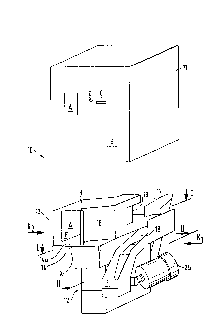
Fig. 1 shows an inventive device 10 for handling returnable cans, which device
S comprises a cover 11 and above a lower press unit 12 an upper trans~er unit 13.
~In Fig. ~, the sover 11 is removed from ~op of the device.) In accordance with
the invention, the transfer unit 13 is formed such that it comprises a conveyor 14
and most preferably a belt conveyor. In the figure, a returnable can is fed to an
inlet gate A, and if said can is rejected, it is returned to the customer and can be
10 removed from an outlet gate B.
The inventive equipment thus comprises a conveyor passage F on top of a belt
run 14a. At the end of the belt run 14a is located a first passage 17, preferably
a trough, via which the returnable can~ which has been accepted, is transferred
15 to the press, which ~orms the can into a smaller volume. At the end o~ the belt
run 14a is further located on the other side of the belt run a second passage 18,
preferably a trough, via which a rejected can gravitationally transfers to the
outlet g~te B.
20 The conveyor passage F is comprised of side walls 16 and a ceiling H, and the bottom of the conveyor passage F is formed by the movable belt run 14a.
According to Fig. 1, the equipment further cvmprises a device 19 for removing
a rejected can ~rom the belt run, preferably a solenoid kicker, which transfers the
can from top of ~he the belt run 14a to said passage 18 designed for rejected
25 cans. The device 19 preferably comprises a piston part or the like, which hits the
rejected can when the can enters at the device 19. In the cover 11, an acknowl-
edgement button is marked with the letter C and an outlet opening for a receipt
and/or compensation money is marlced with the letter G.
Fig. 2 shows a section I-l of Fig. 1. The passage F is bounded by side walls 16a1,
16a2 and 16a3 as well as 16b1, 16b2 and 16b3. The side walls 16a1 and 16a2.
Iike correspondingly their side walls 16b1 and 16b2 paralled ~hereto are loeated
2 0 ~
WO 92/05~23 PCr/F191/00263
diagonally relative to a center axis X of the belt run 14a. According to the figure,
the returnable can transfers, conveyed by the belt run, along the passage F suchthat the returnable can transfers to the side wall 16a2. The returnable can
transfers in the direction of an arrow S1 and rotates in compliance with the side
5 wall 16a2 and along it to a point N a$ the end of the side wall 16a~, and fromsaid end the returnable can is guided in compliance with the side wall 16a3 to
tbe vicinity of the rejection device 19 in an exact alignment, which is given tosaid returnable can by the side wall 16a3 parallel to the center axis X of ~he belt
run 1~a. Since the side wall 16a2 is in a diagonal position relative to the center
10 a~cis X of the belt run 14a, it gives the renlrnable can P a rotational movement
S2. The rotation of the returnable can thus occurs against the side wall 16a2.
The material of the wall 16a2 is selected so that it has good frictional properties,
whereby the can does not slide on the surface :l6a2 but rotates in compliance
with said sufface. The dark and protected space between the walls 16a~ and
16b2 can then be used for reading a line code. A scanner 24, which reads the
line code on the returnable can, is advantageously fitted to the wall 16b3, and in
the figure, it is according to an arrow d fitted to send a scanning strip along the
wall 16a~ towards the rotating can P. As the can rotates, the line code on the
can in some phase inevi~ably enters the sc`anning line, whereby the scanner 24
reads the line code of the re~urnable can. The purpose of the walls 16 and the
ce;ling H ;s also to form such a passage F, from which it is difficult to reach the
returnable can, when it has once been transferred to the inlet gate A. The wallsthus bound the dark and protected space, which comprises the scanner 24,
where~y the reading accuracy of the scanner improves, since external light is
prevented from entering into the dark space between the walls 16a2 and 16b2.
The rotational movement provided for the can by means of the wall 16a2 in turn
makes it possible that the scanner is capable of reading the line code, since inthe rotational movement S2, the line code in some phase enters the scanning
30 line.
In the vicinity of the gate A is located an identification device 20, preferably a
, :. ' :
- ; I ,
4 1 ~
WO 92/05523 PCr/FI91/OD263
photocell, an infrared rell or some other corresponding identification device, by
means of which the entry of the returnable can into the ~ate A is identified. This
info~nation is further transmitted ~o the central unit of the device, which unitstarts up a motor ~5, whereby the belt 14a receives a rotational movemen~.
At the initial end of the wall 16a3, 16b2 are located sensors, preferably light
sensors, which are comprised of transrnitter/receiver units 22a1, 22bl, 22a2,
22b2. The sensors are located one after the other, and by means of them, the
travelling direction of the returnable can is identified and possibly also the fact
10 that the returnablc ean is in a vertical position on top of the belt run 14a. An
incorrect use is eliminated by means of the above-mentioned light-sensor devices,
since the travelling direction of the returnable can is determined by means of the
light sensors, and when the travelling direction is the direction L1, an acceptance
signal is given thereof. After the transrnitter/receiver light sensor devices islS located a weight identification device 21, preferably a strain-gauge transducer
located under the belt 14a. After the weight identification device 21 is then
located a material identification device 23, preferably an inductive sensor, which
checks the material of the returnable can, and when it detects that e.g. a steelcan is concerned, the central unit starts up after a certain delay the kicker 19,
20 which transfers a rejected retumable can from the belt run 14a to the passage19, which is preferably a trough, via which the non-accepted can is transferrçd to
the outlet gate B. From the gate B, the customer can pick up the non-accepted
returnable can back to her/himself.
25 Fig. 2 further shows the above-mentioned branching point, whereby an acceptedcan transfers from the end of the belt conveyor in the direction of ~he arrow L2direetly ~o the passage 17 and to the press, and a rejected can transfers in thedirection of the arrow L3 to ~he passage 18 and to the gate B.
30 Fig. 3 illustrates the actuators of ~he inventive device. The motor 25 is preferably
an electric motor, which rotates via a herringbone gear 26 a press drum 27 of the
press unit 12.
. . . .
,. ~ , . :, ~. . :
wo 92/05s23 2 0 ~ ~3 ~18 PCT/F191/00263
The press drum 27 comprises a shell 28 and therein wings 29 or the like. The
ends of the shell 28 have end flanges 30, which con prise shafts 31a and 31b. I he
shaft 31b, ~n ~he side opposit~ to the motor 25, is co3mected to a belt pulley 32
~he mo~or ~ is preferably an elec~ric motor. When ~he press drum 27 is thus
~o~a~ed in the directi~ns ~ ~e ar~ows, the belt pulley 32 is r~tated and a belt 33
is moved, which is as a closed loop guided via the first belt pulley 32 and a
second belt pulley 34. The belt pulley 34 is coDnected to a first turT~ing roll 35 of
the belt run 14a, to its shaft 35a, and provides a drive for the belt run 14. A
second turning roll 36 of the belt r~n 14 is located near the inlet gate A. The
~urning rolls 36 and 35 are mounted on the body of the device w~th bearing
de~ices (not sho~iwn).
Fig. 4 shows the inventive device from the direction of the arrow K1 of Fig. 1.
Fig. 5 shows the device of the figure seen from the direction of the arrow K.l of
Fig. 1.
The rotational drive of the belt 14a of the transfi~r conveyor 14, preferably a belt
conveyor, is preferably thus taken from the belt 3?~ shown in Fig. 5, which is
further driven by one end shaft 31b of the press drum 27. One motor 2S thus
rotates the convey~r belt 14a and the press drum 27. When the placement of a
can on the belt rlm 14a is detected by the identification device 20, preferably a
photocell, the motor 25 automatically starts up.
Fig. 6 shows a section Il-II of Fig 1. The press unit 12 comprises the press drum
27, behheen the shell 28 and a counterpart 38 of which forms a wedge-like press
gap 37. When the press drum 27 is rotated, the wings 29 transfer the returnable
can by ~orce into the wedge-]ike gap 37, which narrows in a wedge-like manner.
The returnable can is formed into a flat longitudinal space-saving form. Accord-3Q ing to Fig. 6, the counterpart 38 is fitted to turn at an articulated point 3~ a~ainst
the spring force of a spring ~0. The press drive thus receives flexibili~, since the
CounterpaTt 38 can be moved against the spring force of ~he spring 40. In
.
.... . . .
WO 92/05~23 2 0 6 ~ 3 pcr/Fl9l/oo263
addition, the counterpart 38 is provided with a rotatable roll 41, which facilitates
the travellillg of the can at the narrowest poin~ of the gap 37 and the removal of
the can from the gap and further to a storage T.
5 It is also possible tQ use in the in~ention an embodiment, in which the conveyor
is driven directly by its own motor,, preferably an electric motor, which connects
from its outlet shaft either directly or via a gear system to the roll driving the
belt 14a.
10 Fig. 7 illustrates an embodirnent, in which both aluminium cans and steel cans
are crushed. The equiyment is provided with a magnetic wheel 42, whereby the
steel cans stick to the magnetic wheel and transfer, loosened by a guide 43, to a
passage 44, which transfers the returned steel caI~ to its own press or to a certain
sector of the press drum. The aluminium can tr.msfers directly on the belt run
15 14a to a passage located at the end of the belt run, which passage transfers the
alurninium can to its own press or to a certain slec~or of the same press. In the
embodiment of Fig. 7 is given a receipt for or directly a compensation correspon-
ding to the returned number of steçl cans and aluminium cans.
20 Fig. 8 shows an embodiment of the inventive device, in which the aluminium
cans and the steel cans are separated after the press drum by the rotatable
magnetic wheel 42, which is fitted after the press gap 37. The magnetic wheel 42transfers e.g. the alurr~irlium cans directly to a storate station T1 located below
~he magnetic wheel 42, whereas the steel cans sti~k to fhe magnetic wheel 42,
25 which transfers them above a storage T2, where the guide 43 loosens the steelcan magnetically stuck to the magnetic wheel 42 from the magnetic wheel 42.
The steel can then drops into its own storage T2. In this embodiment of the
invention, one press unit can thus be used and the separation of the Al/Fe cans
occurs after the pressing occurrence.
Fig. 9 is a block diagram representation of the operation of the inventive device.
In the first step, the returnable can is fed into the inlet opening A. The photocPll
.
-. . -
2~8~1~
wO 92/05~23 Pcr/~lsl/oo263
detects the returned can and starts up the rnotor. In the next step, the line code
is scarmed, as the returnable can travels on a diagonal surface diagonally relative
to the center axis X of the conveyor and diagonally relative to the travelling
direction of the conveyor belt. In the next s~ep, a pair of photocells idenlifies the
S travelling direction of the can. After this, the weight is identified from under the
belt by the vveight identification device 21, preferably a strain-gauge transducer,
and in the final step, an inductive sensor identifies the material of the returnable
can. If the can is accepted, the solenoid does not react and the can transfers to
a passage leading to the press. If the can is rejected, the solenoid or some other
10 corresponding reje~or transfers the non-accepted returnable can to its own
conveyor passage, from which the can transfers back to the vicinity of the frontpanel of the device, where is located the outlet gate B for rejected returnable
cans.
.
.
.
,