Note: Descriptions are shown in the official language in which they were submitted.
7 7 2
- 1 - FS 1484
METHOD AND APPARATUS FOR THE PRODUCTION OF
NODULAR OR COMPACTED GRAP~ITE IRON CASTINGS
This invention relates to a method and
apparatus for the production of nodular or compacted
graphite iron castings, and it will be described with
particular reference to the casting of nodular graphite
iron.
Nodular graphite iron (also known as ductile
iron or spheroidal graphite iron), is iron in which the
graphite is present as nodules or spheroids. In
compacted graphite iron (also known as vermicular
graphite iron or quasi-flake graphite iron) the form of
the graphite is intermediate between the flake graphite
form of grey cast iron and the nodular form of nodular
iron.
Nodular iron is commonly produced by treating
molten iron with magnesium. Small amounts of rare
earths are often added in combination with magnesium.
Rare earths and elements such as calcium and yttrium
which are capable of producing nodular graphite are
seldom used on their own.
All the above mentioned elements are easily
oxidised and magnesium is particularly difficult to
handle because it boils at a temperature of a little
above 1100C while the normal casting temperature for
molten iron is about 1400 C.
2068772
- 2 - FS 1~84
Particular magnesium-containing alloys used
for magnesium treatment are for example a 5 - 10~ by
weight magensium-containing ferrosilicon for over-
pouring and 20 - 40% by weight magnesium-containing
ferrosilicon for plunging. Coke impregnated with pure
magnesium is used for plunging and special treatment
vessels and processes are also used for treatment with
pure magnesium or with special alloys.
All these methods have in common the fact that
the magnesium treatment must be carried out at
temperatures which are substantially above the desired
casting temperature. Normally the treatment
temperature is about 1500C.
Furthermore, it is common to all these
methods, that the magnesium treated iron must be
inoculated either in the treatment ladle or directly in
the metal stream during the pouring of individual
moulds or in the mould in order to form the nuclei in
the cast metal which are necessary to avoid the
formation of undesirable white iron structures.
During the process of rationalisation and
improving the working environment within foundries over
the course of the last ten or so years, many mechanised
or automatic pouring units have been brought into use.
Holding magnesium treated iron in such heated or
unheated pouring units has resulted in particular
problems namely:-
2068772
- 3 - FS 1484
a) an excessive loss of magnesium from the
molten iron
b) build-up of magnesium reaction products in
the pouring unit. For this reason
cleaning and~or renewal of the refractory
lining is necessary at frequent intervals
c) the regulation of a consistent level of
inoculation is difficult and it is only
possible to inoculate accurately in the
pouring stream whilst pouring individual
moulds.
In British Patents Nos. 1 278 265 and
1 511 246 a method is described for the treatment of
iron in the mould with magnesium. In this method a
nodularising agent is introduced into the mould in one
or more intermediate chambers. This method only
provides a solution to the problems listed under a) and
b) above.
The major disadvantages of this method are the
poor utilisation of the available mould area leading to
a poor yield of casting from a given mould and the poor
adaptability of the method to variable process
conditions such as temperature and sulphur content.
The poor utilization of the mould area is due to the
need for additional reaction chambers; an adjustment is
only possible by changing the running system.
British patent specification No. 1 527 054
describes a process for injecting powdered or granular
ferrosilicon-magnesium alloys into the pouring system.
2068772
- 4 - FS 1484
It has been shown that the process which has been
described is not industrially applicable and yields,
even under experimental conditions, only by chance
sufficient residual magnesium and therefore spheroidal
graphite. Furthermore, a number of factors such as the
chemical composition of the alloy, the dependence of
the magnesium recovery on the alloy grading and the
type and dimensions of the running system need to be
considered.
European patent Application No. 0 347 052
describes a mould and process for the production of
nodular graphite or compacted graphite iron castings in
which a magnesium-containing and silicon-containing
treatment agent is added from a dispenser to a stream
of mc-lten iron in the sprue of the mould. The mould
contains a ceramic filter and the various parts of the
mould have a defined relationship one with another, and
the particle size of the treatment agent is controlled
so that it is within the range of from 0.2 mm to 4 mm.
In European Patent Application No. 0 347 052
the dispenser which is used to deliver the treatment
agent into the stream of molten iron may be for example
apparatus of the type described in British Patent
Application No. 2 024 029A. That apparatus has a
nozzle which is connected to a source of compressed air
or an inert gas, means for feeding a treatment agent
into the flow of gas from the nozzle and a detector
which senses the presence and absence of a stream of
molten metal lying in the path of the flow of gas and
treatment agent. The detector controls the flow. of
2068772
- 5 - FS 1484
treatment agent in such a manner that when the stream
of molten metal is present the flow of the treatment
agent is caused to start and when the molten metal
stream ceases the flow of treatment agent is
automatically stopped.
The apparatus which was developed as a means
of achieving metal stream inoculation of molten iron,
dispenses fine granular inoculating agents at a
constant flow rate from the commencement to the end of
casting.
In practice it has been found that the use of
such apparatus for dispensing a treatment agent for
producing nodular graphite iron as described in
EP 0 347 052 can lead to a variable distribution of
magnesium and silicon in a casting due to the fact that
the addition rate of the treatment agent is constant
throughout the casting process. As a result castings
which do not contain all the graphite in the nodular
form can be produced and the castings have variable
mechanical properties.
EP 0 347 052 al~o states that a preferred
apparatus for dispensing the treatment agent also has
means for adjusting the rate of flow of the treatment
agent so that throughout pouring the required amount of
treatment agent is always delivered to the molten
stream.
2068772
- 6 - FS 1484
It has now been found that nodular graphite or
compacted graphite iron castings can be produced in a
reliable and satisfactory manner if the treatment agent
flows at a constant rate while that part of the mould
cavity which is below the ingate is filling, and at a
decreasing rate while that part of the mould cavity is
above the ingate is filling.
According to the invention there is provided a
method for the production of a nodular or compacted
graphite iron casting in a mould having a sprue, an
ingate and a mould cavity, a first part of the mould
cavity being located below the level of the ingate and
a second part of the mould cavity being located above
the level of the ingate, the method comprising
delivering a particulate magnesium-containing and
silicon-containing treatment agent from a dispenser
into a stream of molten iron entering the sprue in such
a manner that the treatment agent is added at a
constant rate of addition while the first part of the
mould cavity is being filled with molten iron, and at a
decreasing rate of addition while the second part of
the mould cavity is being filled with molten iron, so
that the molten iron is treated with the treatment
agent and on solidification of the iron in the mould
cavity a nodular or compacted graphite iron casting is
produced.
According to a further feature of the
invention there is provided apparatus for use in the
method described in the paragraph above the apparatus
comprising a container for holding a particulate
2068772
- 7 - FS 1484
treatment agent, a measuring and data capture device
connected via a signal transforming means to a control
means, conveyor means located below the container and
connected to the signal transforming means, and means
for injecting the particulate treatment agent into a
stream of molten metal.
In a preferred emkodiment of the apparatus of
the invention the container is a hopper, and the
measuring and data capture device is a device of the
type described in German Patent Application Publication
No. 3410845 having an inclined plate on to which the
particulate treatment agent falls and which is
connected to means for continuously weighing the amount
of particulate treatment agent falling on to the plate.
A conveyor means such as a vibrating channel collects
the particulate treatment agent from the container.
The particles then fall from the conveyor means on to
the inclined plate from which they are transferred to
the injection means for injecting the particles into
the molten metal stream.
When molten metal starts to flow the control
means receives a signal from the vessel containing the
metal, for example, from a stopper which is raised to
release the molten metal. The control means, which is
programmed according to the calculations described
below, then continuously calculates the quantity of
metal which is flowing, and also calculates the
quantity of treatment agent rquired at a particular
instant, and sends this information to the signal
transforming means.
20~8772
- 8 - FS 1484
The particulate treatment agent flow rate data
from the measuring and data capture device is
transferred to the signal transforming means which also
receives information from the control means as to the
required flow rate of particulate treatment agent. If
there is a discrepancy between the two the signal
transforming means will automatically alter the flow
rate of the particles in the conveyor means.
The control msans, for example a
microprocessor, is programmed so as to ensure that
during filling of the part of the mould cavity which is
below the ingate a constant amount of treatment agent
is fed to the metal stream, and during filling of the
part of the mould cavity which is above the ingate a
decreasing amount of treatment agent is fed to the
metal stream.
The means for injecting the particulate
treatment agent into a stream of molten metal is
preferably a device similar to that described in
British Patent Application No. 2024029A consisting of a
funnel, a mixing chamber, a delivery tube and a nozzle.
The particles of treatment agent fall under gravity
into the funnel and they are mixed in the mixing
chamber with air or inert gas admitted through the
nozzle. The particles are thus accelerated down the
delivery tube and into the stream of molten metal.
20687~2
- 9 - FS 1484
Depending on the type of mould a vertical
cylinder or alternatively a horizontal half cylinder
may be used as the theoretical model on which the
required flow rates for the treatment agent may be
calculated.
For filling that part of the mould cavity
which is below the level of the mould cavity ingate the
weight of iron flowing per second
m~ = Vl.c
tl
the volume V1 = GF4
c
and the pouring time t1 = Vl
J2g.HF2.R.FF9
where R = coefficient of friction
c = density of the cast metal
GF4 = weight of casting below the level of the
ingate
FF9 = cross-sectional area of the ingate
g = acceleration due to gravity
and HF2 = height of cast column above the level of the
ingate.
2068772
- 10 - FS 1484
For filling that part of the mould cavity
which is above the ingate using the horizontal half
cylinder as the theoretical model the weight of iron
flowing per second
m = Vm.c
tm
the length of the half cylinder L = 2.V2
HF32 .~
the volume of the mth slice
Vm = 2 - HF32.~ 1-(m/n)2.L
n
and the pouring time of the mth slice
tm = Vm
~.h.R.FF9
where h = HF2 - m.N~3
and V2 = GF5
c
where HF3 is the height of the pattern above the level
of the ingate, where n is the total number of slices
and m is any number between 1 and n, GF5 is the weight
of casting above the level of the ingate, and the other
symbols are as indicated above.
20~8772
- 11 - FS 1484
When a vertical cylinder is used as the
theoretical model the weight of iron flowing per second
ml V, ml . C
tml
the base surface area of the cylinder
FFO = V2
HF3
the volume per slice Vml = FFO. HF3
and the pouring time of the mth slice
tml = Vml
~ R.FF9
where h = HF2 - m HF3
n
and V2 = GF5
c
where each of the symbols is as indicated above.
The actual quantity of treatment agent
required at any point in time can be calculated by
multiplying mO, m or m1 by the desired percentage
addition.
2068772
- 12 - FS 1484
In a preferred embodiment of the method of the
invention the iron is cast in a mould having a
treatment sprue, a runner, a slag trap, a -filter
chamber having an ingate and an outlet and having
located therein a ceramic filter having an inlet and an
outlet, a casting cavity ingate, and a casting cavity
and the parts of the mould have a relationship one with
another as defined in European Patent Application
No. 347052. More preferably the vertical cross-
sectional area of the runner is equal to the cross-
sectional area of the ingate of the filter chamber.
The particulate treatment agent used in the
method and apparatus of the invention is preferably a
magnesium-containing and silicon-containing treatment
agent having a particle size of 0.4 mm to 2 mm.
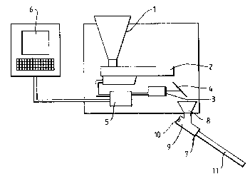
The invention is illustrated with reference to
the accompanying drawing which is a diagrammatic
representation of apparatus according to the invention.
Referring to the drawing apparatus for adding
a particulate treatment agent to a stream of molten
iron in the production of nodular iron or compacted
graphite iron castings consists of a hopper 1 which
holds the particulate treatment agent, a vibrating
channel conveyor 2, a measuring and data capture
device 3 having an inclined plate 4, a signal
transformer 5, a microprocessor 6, and a device 7 for
injecting the particulate treatment agent into a stream
of molten metal. The injector device 7, which is part
of the appai-atus described in British Patent
20~8772
- 13 - FS 1484
Application No. 2024029A, the remainder of which is not
shown, consists of a funnel 8, a mixing chamber 9
having a nozzle lO for admitting compressed air, and a
delivery tube 11.
In use, when flow of molten iron commences,
the microprocessor 6 receives a signal from the vessel
containing the molten iron (not shown) and then
calculates continuously the amount of iron which is
flowing.
Particulate treatment agent falls from the
hopper 1 on to the vibrating channel conveyor 2 which
is connected to the signal transformer 5. The
particulate treatment agent passes along the conveyor 2
and falls on to the inclined plate 4 and from there
into the injector device 7. The measuring and data
capture continuously weighs and records the amount of
particulate treatment agent falling on to the inclined
plate 4 and transmits the recorded data to the signal
transformer 5. The microprocessor 6 is programmed so
as to determine the amount of particulate treatment
agent required at any instant in time based on the
quantity of iron which is flowing and the desired
percentage addition rate of the treatment agent, and
continuously transmits to the signal transformer 5
information on the required amount of treatment agent.
If the actual flow of treatment agent as determined by
the measuring and data capture device 3 is incorrect
the signal transformer 5 will correct the flow of
treatment agent in the vibrating channel conveyor 2.
2068772
- 14 - FS 1484
The particulate treatment agent falls through
the funnel 8 of the injection device 7 into the mixing
chamber 9 and is mixed with compressed air entering
through the nozzle 10 and accelerated down the delivery
tube 11 into the stream of molten metal entering a
mould.
The microprocessor 6 controls the flow of
treatment agent in the manner described above, such
that while the part of the casting cavity of the mould
which is below the level of the ingate is filling with
iron the particulate treatment agent flows at a
constant rate, and while the part of the mould cavity
which is above the level of the ingate is filling the
particulate treatment agent flows at a decreasing rate.
The invention is further illustrated in the
following comparative example.
Two identical bearing housing castings,
symmetrical about one axis of rotation, were produced
in nodular iron using the apparatus shown in the
accompanying drawing (Example 1), and two further
examples of the same casting were produced using only
the apparatus described in British Patent Application
No. 2024029A (Example 2).
The casting had a weight of 77 kg and a total
height of 250 mm. In Example 1 the total addition per
mould of magnesium-containing and silicon-containing
treatment agent which was adapted to the actual amQunt
-` 2068772
- 15 - FS 1484
of iron flowing was 1066 g. In Example 2 1054 g of the
same treatment agent was added to each mould at a
constant rate of 50 g/sec over approximate 21 seconds.
The magnesium and silicon contents were
determined in all the castings at various points, and
the mean value and standard deviation from the mean was
calculated.
The following results were obtained.
EXAMPLE 1
Maqnesium Castinq 1 Castinq 2
Top Centre Bottom Top Centre Bottom
0.023% 0.024% 0.023% 0.023% 0.023% 0.022%
0.022% 0.023% 0.021% 0.022% 0.024% 0.021%
0.022% 0.022% 0.021% 0.023% 0.023% 0.023%
0.023% 0.023% 0.021% 0.022% 0.024% 0.022%
Mean ~x) = 0.0225%
Standard deviation (s) = 0.000933%
x +/- 3s = 0.0197% to 0.0253%
- 16 - FS 1484
Silicon Castinq 1 _astin~ 2
Top Centre Bottom Top Centre Bottom
2.22% 2.25% 2.18% 2.22% 2.20% 2.15%
2.20% 2.17% 2.17% 2.21% 2.26% 2.14%
2.21~ 2.19% 2.19% 2.24% 2.28% 2.20%
2.24% 2.20% 2.17% 2.20~ 2.26% 2.18%
Mean (x) = 2.205%
Standard deviation (s) = 0.00358%
x +/- 3s = 2.098% to 2.312%
EXAMPLE 2
_qnesium Castinq 1 Castinq 2
Top Centre Bottom Top Centre Bottom
0.023% 0.022% 0.020% 0.023% 0.023~ 0.020%
0.022% 0.023% 0.019% 0.021% 0.022% 0.020%
0.022% 0.023% 0.019% 0.023% 0.022% 0.019%
0.022% 0.022~ 0.017% 0.022% 0.022% 0.020%
Mean (xj = 0.0213%
Standard deviation ~s) = 0.001654%
x +/- 3s = 0.0163% to 0.0263%
2068772
- 17 - FS 1484
Silicon Castinq 1 Castinq 2
Top Centre Bottom Top Centre Bottom
2.20% 2.35~ 2.18% 2.31% 2.29% ~.18~
2.26% 2.35% 2.24% 2.24~ 2.34% 2.23%
2.30% 2.28% 2.21% 2.23% 2.27% 2.19%
2.~6% 2.31% 2.15~ 2.33% 2.30% 2.20
Mean (x) = 2.267%
Standard deviation (s) = 0.0575%
x +/- 3s = 2.090% to 2.435%.
In Example 2 which is not according to the
invention the rate of flow rate of the molten iron into
the mould at the beginning of pouring was about 4.5 kg
of iron per second and about 2.5 kg of iron per second
at the end of pouring. As flow rate of the treatment
agent was constant at 50g/sec the actual addition rate
based on the weight of iron was 1.11% at the beginning
and 2.00% at the end.
In example 1 the rate of addition of treatment
agent was controlled by the apparatus of the invention
so that the amount added while the part of the mould
cavity which is below the ingate was filling was
constant and the amount added while the part of the
mould cavity which is above the ingate was filling was
decreasing.
2068772
- 18 - FS 1484
A comparison of the results obtained shows
that the standard deviations for magnesium and silicon
content at a constant rate of addition of the treatment
agent are respectively 77% and 60% higher than when the
rate of addition is as required by the process of the
invention. Furthermore even though the actual amount
of treatment agent is virtually the same in both
examples compacted graphite was found in part of the
castings of Example 2 while the castings of Example 1
contained 100~ nodular graphite.