Language selection

Search

Patent 2068854 Summary

Third-party information liability

Some of the information on this Web page has been provided by external sources. The Government of Canada is not responsible for the accuracy, reliability or currency of the information supplied by external sources. Users wishing to rely upon this information should consult directly with the source of the information. Content provided by external sources is not subject to official languages, privacy and accessibility requirements.

Claims and Abstract availability

Any discrepancies in the text and image of the Claims and Abstract are due to differing posting times. Text of the Claims and Abstract are posted:

  • At the time the application is open to public inspection;
  • At the time of issue of the patent (grant).
(12) Patent: (11) CA 2068854
(54) English Title: IMPELLER FOR CENTRIFUGAL PUMPS
(54) French Title: ROUE A AILETTES POUR POMPES CENTRIFUGES
Status: Term Expired - Post Grant Beyond Limit
Bibliographic Data
(51) International Patent Classification (IPC):
  • F04D 29/24 (2006.01)
  • F04D 29/22 (2006.01)
  • F04D 29/66 (2006.01)
(72) Inventors :
  • COOPER, PAUL (United States of America)
  • SLOTEMAN, DONALD P. (United States of America)
(73) Owners :
  • FLOWSERVE MANAGEMENT COMPANY
(71) Applicants :
  • FLOWSERVE MANAGEMENT COMPANY (United States of America)
(74) Agent: NORTON ROSE FULBRIGHT CANADA LLP/S.E.N.C.R.L., S.R.L.
(74) Associate agent:
(45) Issued: 1998-04-07
(22) Filed Date: 1992-05-15
(41) Open to Public Inspection: 1992-12-22
Examination requested: 1992-05-15
Availability of licence: N/A
Dedicated to the Public: N/A
(25) Language of filing: English

Patent Cooperation Treaty (PCT): No

(30) Application Priority Data:
Application No. Country/Territory Date
719,025 (United States of America) 1991-06-21

Abstracts

English Abstract


A cavitation resistant impeller for liquid-conveying centrifugal
pumps has a plurality of impeller vanes, each vane having, in
combination, a leading inlet edge with a root portion extending
upstream of its tip portion; a vane thickness that is greater
upstream of the impeller throat than the vane thickness
downstream of the impeller throat; and an elliptical nose on the
leading inlet edge. The invention can be used in straight-vaned
impellers or in Francis-type impellers.


French Abstract

Cette invention concerne une roue anticavitation de pompe centrifuge à liquides, qui comporte une série d'aubes ayant, chacune, un bord d'attaque à l'aspiration dont la racine est en amont par rapport à son extrémité; une épaisseur qui est plus grande en amont de l'ouïe qu'en amont de celle-ci; et un nez elliptique sur le bord d'attaque à l'aspiration aspiration. Cette invention peut être adaptée aux roues à aubes radiales ou aux roues de type Francis.

Claims

Note: Claims are shown in the official language in which they were submitted.

The embodiments of the invention in which an exclusive
property or privilege is claimed are defined as follows:
1. In an impeller for liquid-conveying centrifugal
pumps having a front shroud member, a rear hub member, a
plurality of vanes joining inner surfaces of said shroud and
hub members and having leading inlet edges disposed at the
periphery of a circle, and an inlet throat opening between a
suction side of one vane and a pressure side of an adjacent
vane, means for inhibiting cavitation comprising:
a) each vane including:
i) a span between said shroud member and said
hub member;
(ii) a leading inlet edge having a root portion
extending upstream of a tip portion;
(iii) said leading inlet edge forming a concave
surface beginning at a location between said tip portion and
the mid-point of said span, said concave surface extending
upstream to said root portion; and
(iv) a vane thickness upstream of said inlet
throat opening greater than a vane thickness downstream of
said throat opening.
2. The invention of claim 1 in which a line tangent to
said concave surface intersects the inner surface of said hub
member, at an angle which is less than 45 degrees.
3. The invention of claim 2 in which said leading inlet
edge has an elliptical nose.
- 8 -

4. An impeller for liquid-conveying centrifugal pumps
comprising:
(a) a front shroud member;
(b) a rear hub member spaced from said shroud member;
(c) a plurality of vanes therebetween having leading inlet edges
disposed at the periphery of a circle, each pair of vanes
forming an inlet throat opening between a suction side of one
vane and a pressure side of an adjacent vane;
(d) each vane including:
(i) a span between said shroud member and said hub member;
(ii) a leading inlet edge having a root portion extending
upstream of a tip portion;
(iii) said leading inlet edge forming a concave surface
beginning at a location between said tip portion and the
mid-point of said span, said concave surface extending upstream to
said root portion;
(iv) a vane thickness upstream of said throat opening greater
than a vane thickness downstream of said throat opening; and
(v) an elliptical nose on said leading inlet edge.
5. An impeller for liquid-conveying centrifugal pumps
comprising:
(a) a front shroud member;
(b) a rear hub member spaced from said shroud member;
(c) a plurality of vanes therebetween having leading inlet edges
-9-

disposed at the periphery of a circle, each pair of vanes
forming an inlet throat opening between a suction side of one
vane and a pressure side of an adjacent vane;
(d) each vane including:
(i) a span between said shroud member and said hub member;
(ii) a leading inlet edge having a root portion extending
upstream of a tip portion;
(iii) said leading inlet edge forming a concave surface
beginning at a location between said tip portion and the
midpoint of said span, said concave surface extending upstream to
said root portion; and
(iv) an elliptical nose on said leading inlet edge.
-10-

Description

Note: Descriptions are shown in the official language in which they were submitted.


20688~
Docket No. 1293-IR-CA
IMPELLER FOR CENTRIFUGAL PUMPS
BACKGROUND OF THE INVENTION
5 This invention relates to impellers for centrifugal pumps of the
type used to convey liquids. More particularly, it relates to
straight-vaned impellers, commonly called radial impellers, and
also to Francis-type impellers, commonly called semi-axial
impellers.
In high energy pump impellers, cavitation can develop along
impeller blades and adjacent surfaces in the following loca-
tions:
15 a. along the impeller blade surface;
b. near the intersection of the impeller blade with the hub
surface; and
20 c. at the nose of the leading edge of the impeller blade. Such
cavitation can cause rapid erosion of impeller blades at
these locations, leading to early failure of the impeller or
increased need for repairs.
25 An approach to combat this cavitation problem consists of modi-

236~354
flying the curvature of each impeller vane on the suctionside, in the area of the leading edge of the vane. However,
this teaching deals with cavitation along the sides surfaces
of impeller vanes, but does not address the cavitation at the
other above-specified locations. There is a need, therefore,
for an improved impeller that inhibits cavitation along the
impeller blade surface, near the intersection of the impeller
blade with the hub surface and at the nose of the leading edge
of the impeller blade.
According to a broad aspect of the present invention there is
provided an impeller for liquid-conveying centrifugal pumps
having a front shroud member, a rear hub member, a plurality
of vanes forming inner surfaces of the shroud and hub members
IS and having leading inlet edges disposed at the periphery of a
circle, and an inlet throat opening between a suction side of
one vane and a pressure side of an adjacent vane, and means
for inhibiting cavitation. Each vane includes a span between
the shroud member and the hub member. A leading inlet edge of
20 the vane has a root portion extending upstream of a tip
portion. The leading inlet edge forms a concave surface
beginning at a location between the tip portion and the mid-
point of the span. The concave surface extends upstream to
the root portion. The vane also has a thickness upstream of
25 the inlet throat opening greater than a vane thickness
downstream of the throat opening.
The foregoing illustrates limitations known to exist in
present impellers. Thus it is apparent that it would be
advantageous to provide an alternative directed to overcoming
one or more of the limitations set forth above. Accordingly,
a suitable alternative is provided including features more
fully disclosed hereinafter.
.~Y

~lJ6~854
SUMMARY OF THE INVENTION
In one aspect of this invention, this is accomplished by
providing an impeller having a front shroud; a rear hub;
a plurality of vanes spanning the distance therebetween;
an inlet throat opening; and each vane having a span
between the shroud and the hub, a leading inlet edge
having a root portion upstream of its tip portion; a
concave surface on the inlet leading edge beginning at a
point between the tip and the mid-point of the
t
~,

2068854
Docket No. 1293-IR-CA
span and extending to the root portion: and a vane thickness
upstream of the throat that is thicker than a vane thickness
downstream of the throat.
5 The foregoing and other aspects will become apparent from the
following detailed description when considered in conjunction
with the accompanying drawing figures.
BRIEF DESCRIPTION OF THE DRAWING FIGURES
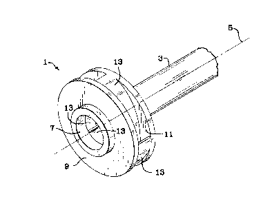
Fig. 1 is an isometric view of an embodiment of the impeller of
this invention:
Fig. 2 is a top view, with the shroud removed, of a straight-
15 vaned impeller, showing a vane according to the prior art and,in dotted line, a vane according to an embodiment of this inven-
tion:
Fig. 3 is a side view, in a plane perpendicular to the face of
20 an impeller vane, along the lines of A-A of Fig. 2: and
Fig. 4 is an isometric view, with the shroud member and part of
the hub removed, of the leading edge of a vane of an embodiment
of this invention showing the thickness of the vane between the
25 leading edge and the throat area, and the elliptical nose of a

20~8~51
Docket No. 1293-IR-CA
vane.
DETAILED DESCRIPTION
5 Fig. 1 shows an isometric view of a straight-vane, single suc-
tion, closed impeller, embodying the invention described herein.
Impeller 1 is mounted on a shaft 3, rotatable about center-line
5. Impeller 1 forms a suction eye 7 through which liquid enters
the impeller 1. Impeller 1 is formed by a front shroud member 9
10 and a rear hub member 11 spaced therefrom. Shroud member 9 and
hub-member 11 have inner surfaces (not shown) substantially
parallel to each other and extending in a plane transverse of,
and perpendicular to, centerline 5 of shaft 3, as is conven-
tional. A plurality of vanes 13 extend between shroud member 9
15 and hub member 11.
Referring now to Fig. 2, vanes 13 are arranged in an annulus,
with leading inlet edges 15 disposed at the periphery 17 of a
circle with a diameter at the centerline 5 of shaft 3, as is
20 conventional. Each vane 13 is identical and a description of
one will suffice for all.
Each vane 13 has a pressure side 19 and a suction side 21. Each
pair of adjacent vanes 13 forms and inlet throat 23 and an out-
25 let opening 25, as is well known. Inlet throat 23 is defined
--4--

2068854
- Docket No. 1293-IR-CA
herein as the shortest distance between a pressure side 19 of a
vane 13 and an adjacent suction side 21 of an adjacent vane 13,
when viewed in a top view. As used herein, the top view is shown
on a plane transverse of, and perpendicular to centerline 5 of
5 shaft 3, as in Fig. 2. Dotted line 27 represents the suction
surface of a vane of this invention, and solid line 29
represents the suction surface of a prior art vane.
When viewed in a top view, the thickness t (31) of each vane 13
10 upstream of throat 23 is greater than the thickness t'(33) of
that same vane 13 down stream of throat 23. The greater thick-
ness t (31j helps to reduce cavitation at various flow rates,
especially at flow rates lower than optimum. The greater thick-
ness t (31) of vane 13 can be achieved by adding material to the
15 vane at the suction side 21, along the length of vane 13 between
the throat 23 and inlet edge 15 upstream thereof. The thickness
t'(33) of vane 13 downstream of the throat 23 is retained in the
range already utilized in the prior art. The inlet throat 23
dimension is, therefore, unchanged over prior art throats which
20 are used, thereby, avoiding cavitation head loss.
Referring now to Fig. 3, a side view of a single vane 13 of this
invention, with parts removed, is shown. As used herein, the
side view is on a plane parallel to the length of centerline 5,
25 and perpendicular to the plane used for a top vièw.

~05~85$
Each vane 13 has a span that extends between, and connects to,
the inner surface 35 of shroud member 9 and inner surface 37
of hub member 11.
Inlet edge 15 of vane 13 has a root portion 39 intersecting
hub inner surface 37 and a tip portion 41 intersecting shroud
surface 35. Root portion 39 is located upstream of tip
portion 41 as indicated by the direction of rotation
represented by arrow 43. When viewed in a side view, tip
portion 41 intersects shroud surface 35 at a substantially
perpendicular intersection, as is conventional, but inlet edge
15 begins to form a concave surface 45 as it extends toward
upstream root portion 39. The concave surface 45 begins to
form at a point along inlet edge 15 which is located between
lS tip portion 41 and the mid-point of the span of vane 13,
represented by dotted line 47. It should be understood that
the beginning of concave surface 45 can start at any point
along inlet edge 15 between the aforesaid tip 41 and mid-point
47. Concave surface 45 extends upstream to root portion 39,
20 as described hereinabove.
For best results, we prefer that the limit of concave surface
45 be defined by angle a (49) formed between inner surface 37
of hub 11 and a line drawn tangent to concave surface 45 at
25 the intersection of concave surface 45 and inner surface 37.
Angle a (49) must be less than 45 degrees, for optimal
results. This
'F''';',
~... _~

20688~4
Docket No. 1293-IR-CA
upstream root configuration provides the benefit of increased
resistance to cavitation, when used in combination with the vane
thickness relationship described hereinabove.
5 Referring to Fig. 4, the inlet edge 15 is shown having a nose
51, that forms an elliptical surface when viewed in top view.
The direction of rotation is shown by arrow 53. The combination
of elliptical nose 51, upstream root portion 39 and differential
vane thicknesses t (31) and t' (33) all combine to provide
10 superior resistance to cavitation formation.
While we have described our invention in a straight-vaned, or
radial, impeller it would be equivalent to provide it in a
Francis-type, or semi-axial impeller, with the same beneficial
15 results. Likewise, it would be equivalent to provide it in an
impeller known in the art as a semi-open impeller.

Representative Drawing
A single figure which represents the drawing illustrating the invention.
Administrative Status

2024-08-01:As part of the Next Generation Patents (NGP) transition, the Canadian Patents Database (CPD) now contains a more detailed Event History, which replicates the Event Log of our new back-office solution.

Please note that "Inactive:" events refers to events no longer in use in our new back-office solution.

For a clearer understanding of the status of the application/patent presented on this page, the site Disclaimer , as well as the definitions for Patent , Event History , Maintenance Fee  and Payment History  should be consulted.

Event History

Description Date
Inactive: Expired (new Act pat) 2012-05-15
Inactive: IPC from MCD 2006-03-11
Letter Sent 2002-06-19
Inactive: Correspondence - Transfer 2002-04-16
Inactive: Multiple transfers 2002-04-16
Inactive: Office letter 2002-02-22
Inactive: Multiple transfers 2002-01-16
Grant by Issuance 1998-04-07
Inactive: Application prosecuted on TS as of Log entry date 1998-01-28
Inactive: Status info is complete as of Log entry date 1998-01-28
Pre-grant 1997-09-22
Notice of Allowance is Issued 1997-04-22
Application Published (Open to Public Inspection) 1992-12-22
All Requirements for Examination Determined Compliant 1992-05-15
Request for Examination Requirements Determined Compliant 1992-05-15

Abandonment History

There is no abandonment history.

Owners on Record

Note: Records showing the ownership history in alphabetical order.

Current Owners on Record
FLOWSERVE MANAGEMENT COMPANY
Past Owners on Record
DONALD P. SLOTEMAN
PAUL COOPER
Past Owners that do not appear in the "Owners on Record" listing will appear in other documentation within the application.
Documents

To view selected files, please enter reCAPTCHA code :


To view images, click a link in the Document Description column. To download the documents, select one or more checkboxes in the first column and then click the "Download Selected in PDF format (Zip Archive)" or the "Download Selected as Single PDF" button.

List of published and non-published patent-specific documents on the CPD .

If you have any difficulty accessing content, you can call the Client Service Centre at 1-866-997-1936 or send them an e-mail at CIPO Client Service Centre.


Document
Description 
Date
(yyyy-mm-dd) 
Number of pages   Size of Image (KB) 
Cover Page 1998-03-24 1 40
Claims 1993-11-06 3 78
Cover Page 1993-11-06 1 14
Abstract 1993-11-06 1 14
Description 1993-11-06 7 205
Drawings 1993-11-06 2 59
Description 1997-04-22 8 232
Claims 1997-04-22 3 82
Representative drawing 1998-03-24 1 10
Correspondence 2002-02-22 1 29
Fees 1997-04-24 1 56
Fees 1996-04-22 1 54
Fees 1995-05-01 1 53
Fees 1994-04-28 1 51
Prosecution correspondence 1993-03-19 13 881
Correspondence related to formalities 1993-11-16 1 35
Courtesy - Office Letter 1993-01-19 1 44
Prosecution correspondence 1996-10-28 2 49
Examiner Requisition 1996-12-23 2 63
Correspondence related to formalities 1997-09-22 1 44
Examiner Requisition 1996-08-30 2 56
Prosecution correspondence 1996-08-06 2 69
Prosecution correspondence 1997-02-17 2 53
Prosecution correspondence 1996-08-06 1 23
Prosecution correspondence 1993-03-19 1 30
Prosecution correspondence 1992-05-15 8 292