Note: Descriptions are shown in the official language in which they were submitted.
CASE 50190
_~_
RECLOS~1~LE PoUCR hId~ biFl'I3~I) ~1D ~1~p7~.R~TU_S
F~DR FoR3~I~C$a F~IaL~I~lC$ ~TD $~°a~IaIZIC3
~aokvround of the Invention
Tgohn3cal Field
The invention relates generally to packaging for
food products, and more particularly to reclosable pouches
and methods and apparatus for .forming, filling and sealing
such pouches,
1~ ~ackaround Tnforanat3on
It is well known in the art that, for certain
food products, efficiency in packaging and acceptable shelf
life can be obtained by hermetically sealing the product in
a package in a form/fill/seal (FFS) operation.
In providing a commercially viable package
through FFS operations, several considerations must be
addressed. one consideration is that the package must be
capable of being opened by the consumer without undue
difficulty. Another consideration is that the package must
be economical to produce, and should be capable of being
formed, filled and sealed at relatively high rates. Tt is
also desirable that the package be durable so as to
withstand the stresses of the FFS operation and subsequent
shipping and handling without damage and withaut
deterioration of appearance.
In recent years, there has been increased demand
for zippers or other means to provide reclosability. One
particular package configuration that has been used
commercially in recent years has a generally rectangular
3o configuration with a reclosable zipper extending within a
fold along one edge, as illustrated in, e.g., U.S. patent
No, 4,589,145. To open the package, the package material
may be slit along the folded edge to gain access to the
zipper, and the zipper is then opened to provide access to
the product. The disposition of the zipper along a long
edge of the package improves access to the package interior
as compared w~.~th disposition of the zipper along one of the
CA 02069030 2004-02-25
-2-
short edges. Where each package is to contain a stack of
sliced product or a relatively large item such as a block
of cheese, the stack or block may be placed on a
horizontally-oriented web and the web can be wrapped around
the item to form the package as described in the above-
referenced Patent No. 4,589,145.
When handling products comprised of numerous
small pieces such as shredded cheese, cereal, etc., it is
generally desirable to have the package partly formed into
a pouch which is open at one end, or along one side, with
the pouch oriented so that the open end or side is at the
top of the partially-formed pouch, and to dispense product
into the partially-formed pouch through the open top or
side.
Vertical FFS operations such as that described in
U.S. Patent No. 4,874,257 represent one approach to
addressing the aforementioned considerations in packaging
food products comprised of numerous small pieces. In the
method of Patent No. 4,874,257, the zipper is disposed
vertically along one side of the package being formed, and
the pouch is filled by gravity-induced flow of product
downward from a filling spout.
Another approach is illustrated by U.S. Patent No.
4,945,714, in which the pouches travel horizontally as they
are formed, filled and sealed. In Patent No. 4,945,714,
the pouch is formed in an inverted orientation from a
single web which has a fold at its lower end and a zipper
within the fold. Two potential problems with this approach
are that penetration of product into the zipper may occur,
and that if the upper end of the pouch is perforated to
facilitate opening, or punched to receive a display hanger,
loss of hermeticity would result.
One problem that must be addressed in any zipper
equipped package such as those mentioned above is that,
where the ends of the zippers extend into seal areas,
difficulty may be encountered in providing hermeticity at
_g_
high throughput rates, due to the increased thickness of
the seal area at the ends of the sipper.
There is a continuing need for improved packages
of the type described above, and for improved FFS
operations for such packages which address the
aforementioned considerations while avoiding f.he
disadvantages of the prior art discussed above.
Summary of the xaae~ent3o~a
The invention provides a novel pouch for
containing food product, and a novel method and apparatus
for forming, filling and sealing the pouch in an inverted
orientation. The method involves providing one or more
webs of material to define a pair of walls for the pouch,
orienting the wall material so that the walls are
substantially vertical, with the web having a horizontal
longitudinal axis: providing interengageable strips of
reclosable fastener material along the web adjacent the
lower edges of the wallso forming vertical side seals;
partially separating the pouches from one another by
2o vertical slitting the web s); filling the pouches through
their open bottoms while in inverted orientation; and
sealing the bottoms of the inverted pouches. Each of the
strips of reclosable fastener material has one or more
fastener members thereon.
~5 In accordance with one aspect of the invention,
a hermetic peelable seal is provided between the product
contained in the interior of the pouch and the reclosable
fastener members. The peelable seal is preferably formed
as a relatively narrow band on the fastener strip material,
30 rather than on the wall material. This provides a saving
of material cost as compared with coating the entire
interior surface of the pouch walls with materials suitable
for formation of a peelable seal. The peelable seal is
sealed prior to filling of the pouches so that product
35 cannot contact the fastener meanbers during or after the
form, fill, seal operation.
_~_ -
The sealing of the peelable seal may be carried
out prior to or simultaneously with sealing of the fastener
strip material to the wall material. The sealing may be
accomplished by a pair of reciprocable sealing bars which
provide predetermined sealing pressure to the seal area
while transferring heat thereto. Gas flush technigues may
be employed to flush the pouch with NZ gas during the form,
fill, seal operation.
The pouch is preferably provided with a line of
perforation adjacent its top end to provide easy-open
access to the reclosable fastener material, and a hole to
receive a display hanger above the fastener members and
beneath the perforations. Referring t~ the completed pouch
in an upright position, ,the interengageable fastener
members are spaced a short distance beneath the top of the
pouch.
Further aspects of the invention are disclosed
below and in the accompanying drawings.
Bri~m Descri,~,at3~aa of the Draw~Laaas
FIG. 1 is an elevational view of a pouch in
accordance with a first embodiment of the invention.
FIG. 2 is a perspective view of the pouch of
FIG. 1, showing a removable portion of the pouch being torn
away to permit access to the interior thereof.
FIG. 3 is a sectional view taken substantially
along line 3a3 in FIG. 1.
FIG. 4 is a sectional view similar to that of
FIG. 3, showing the pouch in an opened configuratiGn.
FIG. 5 is a sectional view similar to that of
FIG. 3, illustrating a pouch in accordance with a second
embodiment of the invention.
FIG. 6 is a diagrammatical plan view of apparatus
far forming, filling and sealing pouches in accordance with
the invention.
FIG. 7 is an elevational view of the apparatus of
FIG. 6.
CA 02069030 2004-02-25
FIG. 8 is a fragmentary diagrammatical plan view
of apparatus in accordance with an alternate embodiment of
the invention.
Detailed Description of Preferred Embodiments
The invention is generally embodied in a
reclosable pouch and a method and apparatus for forming,
filling, and sealing the pouch.
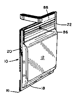
FIGS. 1-4 illustrate a first embodiment of the
invention, comprising a pouch 10 which has first and second
generally rectangular walls 12, 14 sealed to one another
along their bottom edges 16, 18 and side edges 20, 22.
Extending across upper portions of the respective walls are
closure members 24, 26.
Each closure member 24, 26 has a substantially
planar outer surface 28, 30 which is sealed to its
respective associated wall. On their inner surfaces the
closure members have complementary interlocking zipper
profiles 32, 34 extending horizontally along their entire
lengths to provide reclosability for the pouch 10. A non
peelable upper seal 36 is provided along the upper edge of
the pouch between upper portions 35, 37 of the closure
members 24 and 26. A plurality of gripper beads 38 extend
longitudinally above the zipper profiles 32, 34 on the
respective closure members 24 and 26 between the zipper
profiles and the upper seal 36. In the illustrated
embodiments, each closure member has a single pair of
gripper beads 38 formed thereon to facilitate manual
gripping and separation of the fastener profiles 32 and 34.
Extending longitudinally beneath the zipper
profiles and parallel thereto is a hermetic peelable seal
39. The peelable seal is comprised of strips of polymeric
material 39a, 39b on the respective closure members 24 and
26. The strength of the seal 39 is such that it can be
readily opened by application of manual outward force to
the closure members 24 and 26 by the consumer, but is not
susceptible to accidental opening due to normal stresses
associated with product containment during the FFS
CA 02069030 2004-02-25
-6-
operation, and subsequent shipping, handling, and display. The seal preferably
has
an opening force of from about 1.5 to about 6.0 Ibs., and more prefereably
from
about 2.5 to about 3.5 Ibs. The peelable seal 39 is substantially impermeable
to air,
as well as to liquids which may be present in the pouch. Accordingly, the
location
of the peelable seal interiorly of the zipper profiles 32 and 34 prevents any
contents
of the pouch from leaking into the zipper profiles and excludes the inter-
locking
members of the zipper form the hermetic seal area.
The strips of polymeric material 39a, 39b which form the peelable seal
preferably comprise polymeric materials which are known in the art to be
suitable for
this purpose, such as one or more of the following: polyethylene/EVA with a VA
content of between 4% and 22%; polybutylene; *Surlyn; *Bynel; *Saran (PVDC)
copolymer; ethylene acrylic acid copolymer; or methacrylic acid copolymer. As
disclosed in e.g., U.S. Patent No. 4,782,951 a hermetic peelable seal may be
formed
between a *Saran copolymer lamina and an EVA lamina.
Each of the pouch walls 12 and 14 is preferably made of a suitable
laminated material having barrier properties which, when sealed as described
herein, provide hermetically for the pouch. For purposes of example, a
suitable film
for cheese shreds may comprise a linear low-density polyethylene inner layer
in
combination with a polyester or nylon outer layer, and a middle adhesive layer
of
polyethylene. A nylon outer layer is particularly useful in connection with
Swiss
cheese, where a degree of C02 gas permeability is desirable in the packaging.
The
closure members 24 and 26 are preferably made of a low EVA content
polyethylene.
The closure members may be attached to the walls by, e.g., a thin layer or
Surlyn on
each of the closure members and the walls.
To facilitate support of the pouch 10 on a display hanger, a hole 86 is
provided in an upper portion
*Trade-mark
~~ >~~~J
_7-
of the pouch. The hole extends through upper portions of
the walls 12, 14 and through the closure members 24 and 26,
which provide a relatively tough and strong periphery for
the hole to support the weight of the pouch. As shown in
FIG. 1, one or more of the ribs or beads 38 may extend over
the hole to further increase the ability of the pouch to
resist tearing at the hole 86 when subjected to rough
handling during placement on a retail display rack and/or
removal therefrom. Disposition of the hole above the
peelable seal 39 enables hermeticity to be maintained.
Lines of weakness 88 are formed through the walls 12, 14
and closure members 24, 26 immediately beneath the upper
portions 35, 37 of the closure members to enable the upper
portion of the pouch to be torn off, enabling easy manual
access to the gripper beads 38 for separation of the zipper
profiles 32, 34 and peelable seal strips 39a, 39b. The
lines of weakness 88 in the illustrated embodiment take the
form of perforations formed opposite one another through
the respective walls and closure members. The placement of
the perforations 88 above the hole 86 enables the pouch 'to
be supported by a display rack without subjecting the line
of perforations 88 to transverse tensile stresses which
might cause accidental tearing 'thereof.
FIG. 5 illustrates a pouch 41 in accordance with
a second embodiment of the invention. The pouch of FIG. 5
is generally similar to that of FIGS. 1-4, in that it
comprises a pair of generally rectangular walls 40 and 42,
in combination with a pair of closure members 44 and 46
having interlocking zipper profiles 48 and 50 thereon.
tripper beads 52 are provided above the zipper profiles and
a peelable seal 54 extends therebelow. The walls 40 and 42
are sealed to one another along their bottom edges 56, 58
and side edges. However, the pouch of FIG. 5 differs from
that of FIGS. 1-4 in that its upper seal 64 is formed
directly between the walls 40 and 42 of the pouch, rather
than between the closure members. To this end, the closure
members 44 and 46 are spaced beneath the upper edges of the
~.) ~ f~ t) ll
-$-
walls 40 and 42, leaving a peripheral area along the top of
each wall for the upper seal 42. As in the embodiment of
FIGS. 1-4, a hole for receiving a display hanger is punched
through an upper portion of the pouch, and lines of
weakness, e.g., perforations 65, are provided opposite one
another in the walls immediately beneath the seal area 64.
In accordance with a third embodiment of the
invention (not shown] the walls of the pouch may be
constructed of a single web, rather than two separate webs.
The pouch in accordance with this embodiment is
substantially similar to that of FIG. 5, except that the
pouch material is continuous along its upper edge, rather
than comprising two separate walls joined by a seal, and
the pouch material provides a snug fit around the upper
edges of the closure members 44 and 46. As in the other
embodiments, a hole for receiving a display hanger is
disposed adjacent the top of the pouch, with lines of
perforation therebeneath.
FTGS. 6 and 7 illustrate a method and apparatus
for forming, filling and sealing pouches in accordance with
a preferred embodiment of the invention. As described
below, the pouches are formed, filled and sealed in an
inverted configuration. The method will be described with
reference to the pouch 10 described above with reference to
FIGS. 1-4, by describing the successive steps involved in
the formation, filling and sealing of the pouch 10 in its
inverted configuration.
Tn the embodiment of FIGS. 6 and 7, the material
for the walls is provided by first and second rolls 66 and
68 of suitable laminated film in web form. The material
for the closure members is provided by first and second
rolls 70 and 72 of closure strip material. The wall
material as supplied by rolls 66 and 68 comprises webs 90
and 92 of laminated polymeric material. The closure strip
material comprises a first continuous strip 94 having a
female zipper profile thereon, and a second strip 96 having
a male profile thereon.
CA 02069030 2004-02-25
_g_
The first step in the method of FIGS. 6 and 7 is
mating the complementary zipper profiles 32 and 34, i.e.,
pressing the zipper profiles into interlocking engagement
with one another. This step is carried out at a zipper-
s assembly station 74 which comprises a shoe 75 having an
internal surface 76 configured to maintain the opposite
profiles in alignment relative to one another, and to cam
the closure strips 94 and 96 into interlocking engagement
as they advance through the shoe.
The next step is to form the peelable seal 39
between the closure members 24 and 26 at a sealing station
78. At the sealing station 78, a pair of horizontally
oriented, reciprocable heat seal bars 79 are advanced
toward one another to apply pressure and heat to the lower
portions of the closure members which are to form the
peelable seal 39. The advancement of the closure strip
material is intermittent, so that the strip material is at
rest while the heat seal bars 79 are closed.
The next step comprises sealing of the outer
surfaces of the closure strips 94 and 96 to the inner
surfaces of their respective associated wall webs 90 and
92. This is accomplished at an assembly/sealing station 80
at which a second pair of horizontal heat sealing bars 81
are employed to effect the desired sealing. The closure
strips are positioned along the lower edges of the wall
webs as the pouch is formed in its inverted configuration,
so that they will extend across the top of the finished
pouch in its upright configuration.
The line of weakness 88 .is then formed by a
conventional notched perforation wheel on the line at a
perforation station 140. Next, the side margins of the
pouches are sealed by vertical sealing bars 82. In forming
the side seals, the sealing bars 82 crush the closure
strips at the areas 84 which correspond to the ends of the
closure members 24 and 26 in the finished pouch. The
sealing-bars provide an impermeable marginal seal area on
each side of the pouch being formed, along the .entire
~~~~~ )~
-lo-
vertical dimension of the pouch, or at least from the
bottom edges 16, 18 of the walls through the peelable seal
54. The vertical sealing bars 82 preferably include
cutting elements to form vertical slits 139 in the wall
webs 90 and 92, extending upward from the bottom edges of
the respective wall webs to a predetermined level, leaving
links 141 of wall material intact along the upper edges of
the wall webs, while partially separating the pouches from
one another.
to The peelable seal 39 having been formed between
the closure members, the formation of the side seals
enables product 100 to be retained in each of the pouches
being formed. The as-yet-unsealed bottom 98 of the
inverted pouch is held open to provide an opening to
receive the product, and the pocket is filled to a desired
level through a dispensing spout 102, with the peelable
seal 29 preventing the product from reaching the zipper.
The inverted pouch is then gas flushed with NZ or ~0
closed, and sealed along its horizontal top and bottom
edges by additional horizontally-oriented sealing bars 1o4
and 106. The pouch 10 is cut from the preceding and
succeeding pouches by vertically oriented knives 108 which
sever the links 141 and trim the side edges of the pouches,
to complete the FFS operation.
where a punched hole 86 is desired, punch
apparatus 142 may be provided at a convenient location on
the line, zn the apparatus of FIGS. 6 and ?, the punching
operation takes place immediately after sealing of 'the
vertical seals of the pouch, and prior to filling. In
other embodiments of the invention, the order of the steps
may be varied. For example, in the embodiment of F1G. 8,
first and second webs 110, 112 of wall material are
provided by first and second rolls 114 and 116, which axe
supported for rotation about vertical axes. Material for
closure members is provided by first and second rolls 118
and 120 of closure strip material. One roll supplies
_3.l_
closure strip 122 having a female profile, while the other
provides material 124 having a male profile.
In the embodiment of fIG. 8, the lengths of
closure strip material 122 and 124 are joined to their
respective associated webs of wall material 310 and 112 at
two parallel heat sealing stations 126 and 128. The
resulting composite webs of wall and fastener material 130
and 132 then advance over vertical guide rollers 134 and
136 to a sealing assembly station 138 where the zipper
profiles of the closure material are interlocked, and the
peelable seal formed in a manner similar to that described
above with reference to the embodiment of FIGS. 6 and 7.
The remaining steps of forming the side seal, filling,
forming top and bottom seals, and separating the finished
pouches are carried out as described in the embodiment of
FIGS. 6 and 7.
In another embodiment of the invention (not
shown) the formation of the peelable seal is combined with
the operation of sealing the fastener strips to the webs of
wall material. This method is similar to that of FTGS. 6
and 7, except that the sealing station 78 may be
eliminated, and the assemblyf sealing station 80 adapted to
provide heat and pressure to effect both sealing operations
simultaneously.
From the foregoing, ~.~t will be appreciated that
the invention provides a novel pouch and method and
apparatus for fox-ming, filling and sealing the pouch. The
invention is not limited to the embodiments described above
or to any particular embodiments. The invention is more
particularly pointed out in the following claims.