Note: Descriptions are shown in the official language in which they were submitted.
2069288
This invention relates to an improved pole strap
assembly for use by a lineman.
A conventional pole strap is generally of relatively
stiff but flexible material and is attached by snap hooks
at its ends to rings on the lineman's body belt. In use
the pole strap is passed round the far side of the utility
pole or the like to be climbed and supports the lineman at
a working position. When climbing the pole, or descending,
the lineman adopts a side to side rolling movement while
flipping the strap up and down between successive positions
as he climbs up or down the pole. In order to support the
lineman if he loses his footing on the pole, such pole
straps are commonly fitted with braking means which are
intended to engage the pole and support the lineman while
he regains his footing.
Various safety devices having braking features have
been proposed for braking the fall of a lineman. Such
devices are described, for example, in United States
Patents Nos. 869382 (Newton), 1120496 (Holsclaw), 1721517
(Jacobs), 2920714 (Johnson), 3407898 (Johnson), 3840091
(Conlon), 4579196 (Allen) and 4712646 (Page). Many of
these devices rely up the use of biting elements which are
positioned so as to bite into the wood of the utility pole
in the event of a fall, thereby supporting the lineman
'~D
2069288
while he regains his footing. However, such devices are
not effective unless the biting elements are brought into
contact with the surface of the pole. To this end the pole
strap is generally fitted with a cross-strap extending
across the rear face of the pole, the assembly forming a
closed loop encircling the pole and adapted to engage the
pole snugly in the event of a fall.
It is an object of the present invention to provide an
improved pole strap assembly incorporating a cross-strap
which automatically engages the pole in the event of a fall
and is effective on wooden utility poles.
A lineman's pole strap assembly according to the
present invention comprises an outer strap of relatively
stiff but flexible material adapted to extend loosely
around the far side of a pole to be climbed and having end
portions providing attachment means for attachment to a
body belt worn by a lineman, and a cross strap which is
secured at its ends to slide members slidably mounted on
the outer strap so as to define with an intermediate
portion of the outer strap a closed loop for encircling the
pole. The slide members are interconnected by an elastic
tensile member, such as a coil spring or a bungee cord,
which extends around the intermediate portion of the outer
strap along its outer surface. In normal ascent or decent
of the pole the lineman holds the cross strap away from the
pole with his hands while employing the pole strap in the
2069288
conventional way. If he loses his footing, he releases the
cross strap, which is automatically drawn into frictional
engagement with the pole by the elastic tensile member. In
this way the closed loop formed by the cross strap and the
outer strap is tightened onto the pole.
One preferred embodiment of the invention will now be
described, by way of example, with reference to the
accompanying drawings. In the drawings:
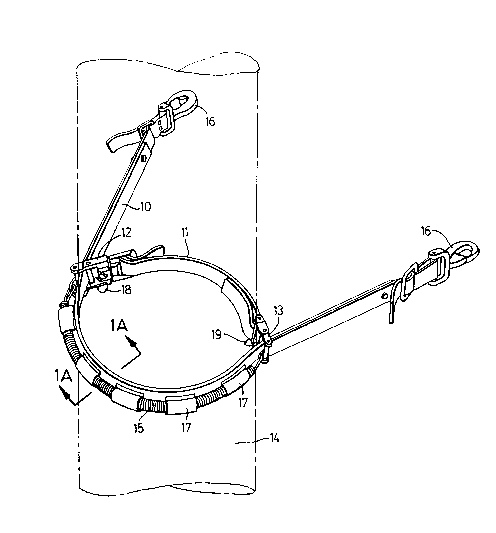
Figure 1 is a perspective view of the pole strap
assembly shown in relation to a utility pole, the cross
strap having been released into engagement with the pole;
Figure lA shows a detail of a modified assembly,
corresponding to a cross sectional view on line A-A in
Figure l;
Figure 2 is a cross sectional plan view of the
assembly shown in Figure 1;
Figure 3 is a view similar to Figure 2 but with the
cross strap held manually away from the utility pole;
Figures 4, 5 and 6 show details of a slide member and
the manner of its attachment to the cross strap;
Figure 7 is a scrap perspective view taken in the
2069288
direction of arrow 7 in Figure 4;
Figure 8 is a scrap perspective view, similar to
Figure 1, but showing a condition in which the cross-strap
has become twisted;
Figure 9 is a sectional plan view, similar to figure
2, but further illustrating the condition shown in Figure
~ 9;
Figure 10 is an enlarged scrap elevation in the
direction of arrow lo in Figure 2;
: 10 Figure 11 is an enlarged scrap elevation, similar to
Figure 10, but illustrating the condition in which the
. cross-strap has become twisted.
Referring to the drawings, and more particularly to
Figure 1 thereof, a lineman's pole strap assembly according
to the invention comprises an outer strap 10, a cross strap
11 secured at its ends to slide members 12,13 which are
. slidably mounted on the outer strap 10, thus defining with
an intermediate portion of the outer strap 10 a closed loop
which encircles the utility pole 14. The slide members
12,13 are interconnected by an elastic tensile member 15
under tension which serves to pull the slide members along
the outer strap and so draw the cross strap into tight
frictional engagement with the near side of the pole, as
shown in Figure 1.
2069288
The outer strap 10 is a pole strap of the conventional
type made of relatively stiff but flexible material, such
as synthetic fibre or leather, and is adapted to extend
around the far side of the utility pole when in use. The
outer strap 10 has snap hooks 16 at its ends by which it
can be attached to rings provided on the lineman's body
belt (not shown). The inner surface of the outer strap 10
is of a material which frictionally engages the pole 14
when pulled against it.
The elastic tensile member 15, which is a coil spring
in the present embodiment, but which may alternatively be
a bungee cord 15' or the like as shown in Figure lA, is
mounted on the outer strap 10 by loops 17 of leather or
other flexible material stitched onto the outer strap 10.
The member 15 is passed through the loops 17 so as to
extend around the intermediate portion of the outer strap
along its outer surface, thus serving to pull the cross
strap 11 against the pole 14. However, during normal
ascent and descent of the pole the lineman must manually
grasp the slide members 12,13 and hold the cross strap away
from the pole, as shown in Figure 3, so that the pole strap
can be manipulated in the normal manner. When the slide
members are released, as when the lineman reaches a working
position, or in the event that he loses his footing while
ascending or descending, the closed loop formed by the
cross strap 11 and the outer strap 10 is closed into tight
2069288
frictional engagement with the utility pole 14, thereby
pulling gaffs 18, 19, which are mounted on the slide
members 12, 13, into biting engagement with the pole.
It is, of course, necessary that the cross strap 11 be
capable of being fastened and unfastened. This can be
achieved by forming the cross strap in two parts to fasten
together, but in the illustrated embodiment of the
invention one end of the cross strap is attached to the
outer strap 10 by means of the slide member 12, which is
constructed as a two-part releasable coupling as best shown
in Figures 4,5 and 6. In this construction one coupling
member 12A is slidably mounted on the outer strap 10 while
the other coupling member 12B is attached to one end of the
cross strap 11. The coupling member 12A comprises a yoke
' 15 12C with a pair of pins 12D, 12E extending between the arms
, of the yoke and defining a slot through which the outer
strap 10 extends. At least one downwardly depending gaff
18 formed on the lower yoke arm is provided for engaging
the pole 14 when it is pulled against it. The base of the
yoke 12C is formed with an internal groove 12F which
communicates with an external key slot (not shown) at right
angles to it. The key slot is adapted to receive a
correspondingly shaped headed pin 12G extending from the
coupling member 12B. As best shown in Figures 4,5 and 6,
one end of the cross strap 11 is fastened to the coupling
member 12B which provides a pair of additional slots
through which the end portion of the cross strap extends,
2069288
the arrangement being such that the length of the cross
strap can readily be adjusted. To fasten the coupling the
lineman inserts the headed pin into the key hole, turns it
through 90 as indicated in Figure 5, and releases the
member 12B so that the pin becomes nested in the groove 12F
where it is retained by a leaf spring 19.
The other slide member 13 comprises a yoke with a pair
of pins mounted between the yoke arms so as to define a
slot through which the outer strap passes, the other end
of the cross strap 11 being permanently attached directly
to the slide member 13.
An important feature of the present invention is that
additional gaffs 20, 21 are provided on the slide members
12, 13 for engaging the surface of the pole 14 in the eYent
that the cross-strap becomes twisted so as to turn the
slide members over. This condition may arise in the
special case in which the lineman loses his footing at the
moment he is flipping the pole strap from between
successive positions on the pole. The gaffs 20, 21 are
formed on the slide members 12, 13 on the sides opposite to
the gaffs 18, 19, and are positioned so as to turn inwardly
and downwardly if the slide members are turned over thus
being brought into biting engagement with the pole 14
should this condition arise. The condition is illustrated
in Figures 9 and 11.
' ' ' '` ''~ ~
20~9288
To sum up, the invention provides a pole strap
assembly in which the pole strap and an associated cross-
strap are interconnected in such a way as to form a closed
loop encircling the pole, the loop being closed
alltomatically into tight engagement with the pole when the
cross strap is released by the lineman, should he lose his
footing on the pole. The cross-strap is connected to the
pole strap by slide members which are interconnected by an
elastic tensile member, and the slide members are provided
on their opposite sides with gaffs positioned to bite into
the pole which the cross-strap is released.