Language selection

Search

Patent 2069385 Summary

Third-party information liability

Some of the information on this Web page has been provided by external sources. The Government of Canada is not responsible for the accuracy, reliability or currency of the information supplied by external sources. Users wishing to rely upon this information should consult directly with the source of the information. Content provided by external sources is not subject to official languages, privacy and accessibility requirements.

Claims and Abstract availability

Any discrepancies in the text and image of the Claims and Abstract are due to differing posting times. Text of the Claims and Abstract are posted:

  • At the time the application is open to public inspection;
  • At the time of issue of the patent (grant).
(12) Patent: (11) CA 2069385
(54) English Title: TREBLE HOOK
(54) French Title: HAMECON TRIPLE
Status: Expired and beyond the Period of Reversal
Bibliographic Data
(51) International Patent Classification (IPC):
  • A01K 83/00 (2006.01)
(72) Inventors :
  • GOWING, JIM (United States of America)
(73) Owners :
  • EBSCO INDUSTRIES, INC.
(71) Applicants :
  • EBSCO INDUSTRIES, INC. (United States of America)
(74) Agent: SMART & BIGGAR LP
(74) Associate agent:
(45) Issued: 1995-12-26
(22) Filed Date: 1992-05-25
(41) Open to Public Inspection: 1993-11-26
Examination requested: 1992-05-25
Availability of licence: N/A
Dedicated to the Public: N/A
(25) Language of filing: English

Patent Cooperation Treaty (PCT): No

(30) Application Priority Data: None

Abstracts

English Abstract


A treble fishing hook includes an elongated shank which has
a first end and a second end. An eye is secured to the first
end of the shank. Three barb-carrying bight portions are
secured to the second end of the shank with the three bight
portions being equally spaced about the axis of the shank and
separated by an angle of about 120. Each of the bight portions
is bent outwardly from the shank so as to lie in a plane which
extends at an angle of from about 14 to about 20 to the axis
of the shank. A barb is carried on each of the bight portions,
and each barb is angularly displaced out of the plane of the
bight portion.


Claims

Note: Claims are shown in the official language in which they were submitted.

THE EMBODIMENTS OF THE INVENTION IN WHICH AN EXCLUSIVE
PROPERTY OR PRIVILEGE IS CLAIMED ARE DEFINED AS FOLLOWS:
1. A treble fishing hook comprising:
an elongated shank having a first end and a second end;
an eye secured to the first end of the shank; and
three barb-carrying bight portions secured to the
second end of the shank, said bight portions being equally
spaced from each other about the axis of the shank, and each
lying in a plane which extends at an angle of from about 14° to
about 22° to the axis of the shank; and
a barb carried on each of said bight portions and
angularly displaced from the plane in which the bight portion
lies so as to be disposed in a plane which projects at an angle
of from about 12° to about 22° with respect to the plane of the
bight portion.

Description

Note: Descriptions are shown in the official language in which they were submitted.


2 0 6 9 3 8 5 PATENT
APPLICATION
TREBLE HOOK
Field Of The Invention
This invention relates to an improved treble barb fishing
hook.
Brief Description Of The Present Invention
5This invention provides a treble-barb fishing hook which, by
reason of its geometric configuration, has enhanced retention
capability to prevent a fish which has struck the bait and
become impaled on the hook from disengaging the hook. Further,
and importantly, as the fish attempts to spit out or throw the
10hook, the hook actually becomes more firmly and deeply impaled
in the jaw of the fish so that fewer fish are lost when the hook
of the present invention is used in fishing.
Broadly described, the fishing hook of the present invention
comprises a treble hook having three barbs which are
15symmetrically arranged and equidistantly spaced about the axis
of a single shank portion to which each of the three barbs is
connected by an intervening bight portion. Each of the bight
portions of the hook is bent outwardly from the shank so as to
lie in a plane which extends at an angle of from about 14 to
20about 22 to the axis of the shank. The barb carried on the
opposite end of each bight portion from the end of the bight
portion connected to the shank is angularly displaced from the
~f-

2069385
plane in which the bight portion lies so as to be disposed in a
plane which projects at an angle of from about 14 to about 22
to the plane of the bight portion.
As the fish which has struck the bait and has been impaled
by the barb pulls on the hook or attempts to spit out the hook,
the point penetrates at the angle of the canting or displacement
of the barbs, and each time the fish pulls on the hook or tries
to dislodge it by running or jumping, the points of the hook
spiral, and thus the fish has, in almost all cases, two, and
sometimes all three, barbs impaled in him.
An important object of the present invention is to provide
an improved treble hook which has greater retention capability
for retaining a fish which has struck the hook and become
impaled on at least one of the barbs thereof.
Another object of the invention is to substantially increase
the ratio of catches per strike by the use of an improved treble
hook by an angler while fishing.
GENERAL DESCRIPTION OF THE DRAWINGS
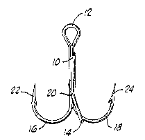
Figure 1 is a top plan view of a treble hook constructed in
accordance with the present invention.
Figure 2 is a side elevation view of the treble hook shown
in Figure 1.
Figure 3 is an enlarged side elevation view of the treble
hook shown in Figures 1 and 2, but having two of the barbs and

- 2069385
their respèctive bight portions removed in order to show the
angular inclination of each of the bite portions with respect to
the axis of the shank of the hook.
Figure 4 is an enlarged side elevation view of one barb and
bight portion of the hook after the hook shank, bight portion
and barb has been rotated through 90 from the position thereof
depicted in Figure 3.
Figure 5 is an enlarged view of the barb carried at the tip
end of each bight portion of the hook, and showing the way in
0 which the barb is twisted out of the principal plane of the
bight portion of the hook so as to be offset laterally
therefrom.
DETAILED DESCRIPTION
OF A PREFERRED EMBODIMENT OF THE INVENTION
The treble hook of the invention includes a conventional
elongated shank portion 10 which has a first end and a second
end. The first end of the shank 10 carries a suitable eye 12 to
which a flexible retrieving line (not shown) can be attached in
conventional fashion. In most treble hooks, the shank portion
10 actually has three straight parts secured together as shown
so that the longitudinal axes of the three parts are parallel.
As is conventional with treble hooks, the hook carries three
barbs at the outer ends of curved bight portions which are
attached to the three parts of the shank portion 10 and support
the barbs at properly spaced intervals. In the illustrated

2069385
embodiment of the present invention, there are three bight
portions 14, 16 and 18 which are arcuate or curved portions of
rigid wire or the like. Each of the bight portions has one end
connected to one of the parts of the shank 10 and carries a
sharp barb or point at its other or free end. Thus, the bight
portion 14 carries a barb 20 at its outer end. Similarly, the
bight portion 16 carries a barb 22 at its outer end and the
bight portion 18 carries a barb 24 at its outer end.
The bight portions 14, 16 and 18 are angularly spaced about
0 the axis of the shank 10, so that each pair of bight portions
defines an angle of about 120 therebetween. Each of the bight
portions is bent out of a plane containing the shank 10 so as to
lie in a plane which extends at an angle of from about 14 to
about 22 to the longitudinal axis of the elongated shank. This
relationship is best illustrated in Figures 2 and 3. In Figure
3, the angle at which the axis of the shank extends to the plane
which contains the bight portion 14 is designated alpha, , and
is preferably about 18.
In referring to Figure 5, it will also be noted that each
barb carried on the free outer end of each bight portion is bent
laterally or oriented to lie in a plane which extends at an
angle, ~, of from about 14 to about 25 with respect to the
principal plane in which curved bight portion which carries it
lies. The preferred offset or angulation is about 20. Thus,

2069385
both the barb and its respective bight portion are disposed in
offset planes which are angled with respect to each other, and
the plane of the bight portion is angled with respect to the
plane in which the longitudinal axis of the shank lies.
The angular inclination of the bight portions in their
connection to the shaft, and of the barbs relative to the planes
of the bights, causes the hook to undergo a spiraling movement
as one of the barbs is touched by the fish. Stated differently,
the hook barbs or points, in being canted at the described angle
0 with respect to the plane containing the bight portion the
shank, cause the treble hook to undergo rotation upon
penetration of the mouth of the fish.
The fact that the hook points or barbs are penetrating
along spiral or twisting paths makes it more difficult for the
hook to be shaken out or thrown free by the fish.
Although a preferred embodiment of the invention has been
herein illustrated and described, the structure of such
preferred embodiment may be slightly altered without departure
from the basic principles of the invention. Such changes can be
effected while remaining within the basic principles of the
invention, and are therefore intended to be encompassed within
the range of equivalents of the appended claims.

Representative Drawing
A single figure which represents the drawing illustrating the invention.
Administrative Status

2024-08-01:As part of the Next Generation Patents (NGP) transition, the Canadian Patents Database (CPD) now contains a more detailed Event History, which replicates the Event Log of our new back-office solution.

Please note that "Inactive:" events refers to events no longer in use in our new back-office solution.

For a clearer understanding of the status of the application/patent presented on this page, the site Disclaimer , as well as the definitions for Patent , Event History , Maintenance Fee  and Payment History  should be consulted.

Event History

Description Date
Time Limit for Reversal Expired 2004-05-25
Letter Sent 2003-05-26
Inactive: Late MF processed 2001-06-28
Letter Sent 2001-05-25
Grant by Issuance 1995-12-26
Application Published (Open to Public Inspection) 1993-11-26
All Requirements for Examination Determined Compliant 1992-05-25
Request for Examination Requirements Determined Compliant 1992-05-25

Abandonment History

There is no abandonment history.

Fee History

Fee Type Anniversary Year Due Date Paid Date
MF (patent, 6th anniv.) - standard 1998-05-25 1998-03-24
MF (patent, 7th anniv.) - standard 1999-05-25 1999-05-06
MF (patent, 8th anniv.) - standard 2000-05-25 2000-05-23
Reversal of deemed expiry 2001-05-25 2001-06-28
MF (patent, 9th anniv.) - standard 2001-05-25 2001-06-28
MF (patent, 10th anniv.) - standard 2002-05-27 2002-05-14
Owners on Record

Note: Records showing the ownership history in alphabetical order.

Current Owners on Record
EBSCO INDUSTRIES, INC.
Past Owners on Record
JIM GOWING
Past Owners that do not appear in the "Owners on Record" listing will appear in other documentation within the application.
Documents

To view selected files, please enter reCAPTCHA code :


To view images, click a link in the Document Description column. To download the documents, select one or more checkboxes in the first column and then click the "Download Selected in PDF format (Zip Archive)" or the "Download Selected as Single PDF" button.

List of published and non-published patent-specific documents on the CPD .

If you have any difficulty accessing content, you can call the Client Service Centre at 1-866-997-1936 or send them an e-mail at CIPO Client Service Centre.


Document
Description 
Date
(yyyy-mm-dd) 
Number of pages   Size of Image (KB) 
Drawings 1994-06-24 1 17
Abstract 1994-06-24 1 23
Claims 1994-06-24 1 25
Description 1994-06-24 5 181
Abstract 1995-12-25 1 19
Description 1995-12-25 5 172
Drawings 1995-12-25 1 18
Claims 1995-12-25 1 23
Representative drawing 1998-10-01 1 3
Maintenance Fee Notice 2001-06-25 1 178
Late Payment Acknowledgement 2001-07-15 1 171
Maintenance Fee Notice 2003-06-22 1 172
Fees 2001-06-27 1 32
Fees 1998-03-23 1 36
Fees 1997-03-20 1 29
Fees 1996-02-27 1 27
Fees 1995-05-11 1 31
Fees 1994-04-12 1 33
Prosecution correspondence 1993-03-04 1 33
Prosecution correspondence 1992-05-24 11 362
Courtesy - Office Letter 1993-01-21 1 43
Correspondence related to formalities 1995-10-19 1 33