Note: Descriptions are shown in the official language in which they were submitted.
207002~
APPARATUS FOR FORMING DOUGH
Field of the invention
The invention relates to an apparatus for forming portioned dough
pieces, in particular to an apparatus for flattening and/or rolling of
portioned dough pieces, preferably of round-kneaded dough pieces that are
delivered up from a head machine, preferably by means of conveyor belts, for
example divergent belts, to a first endless running belt means that
leads the dough pieces to a forming station, for example to a flattening
station disposed above that belt means, a second endless running belt
means being disposed below the first running endless belt means, to which
second belt means the dough pieces are delivered up by the first endless
running belt means.
The prior art
Such known apparatus produce flat dough pieces that, if desired,
are then rolled, for example for producing crescent rolls, salted rolls or
the like. The known apparatus have a considerable overall length, in
particular then, if the flattened dough pieces must be rolled, because
then two working stations are disposed one behind the other, namely the
flattening station and the rolling station. The second endless running belt
to which the dough pieces finally are delivered up, leads the dough pieces
to the further working place. Therefore, as a rule, the output end of
the machine is disposed in a considerable distance from the head machine so
that two persons are necessary to operate the machine.
Summary of the invention
The invention has at its object to improve such an apparatus so that
the overall length is shortened and that the machine can be operated by one
single person only. Further, the invention has at its object to make use of
` 2n7~02~
- 2 -
the second endless running belt means disposed below the first endless
running belt means so that this second belt is used for a further working
purpose. The invention solves this tast - starting from the initially
described known embodiment - by the features that the carrying runn of the
second endless running belt conveys the dough pieces back in direction to
the head machine and that this carrying run together with the lower run of
the first endless running belt constitutes a further forming device for the
dough pieces. In such a manner, the dough pieces are conveyed back in the
region of the head machine so that they can be taken off from the second
endless running belt or, respectively, from a drawer connected thereto, by
the person operating the head machine. A further advantage consists in that
the operating person can easily and quickly determine from the first
delivered dough pieces whether or not the desired adjustment of the head
machine is given, so that this person can change this adjustment at the
earliest possible moment. Within the known construction this is not so
easily possible because within this known embodiment the person operating
the head machine must at first walk towards the output end of the apparatus
and must inspect the dough pieces there, then this person must walk back to
the head machine in order to change its adjustment, or two operating persons
must communicate by shouts. However, the carrying run of the second running
endless band conveying the dough pieces back to the head machine again has
not only this function but constitutes also a support member for the dough
pieces during the forming action of the lower run of the first endless
running beltmeans. This first endless running belt means, therefore, acts
on the dough pieces at two forming operations from which the first is
exerted by the forming station disposed above the first endless running
belt, whereas the second forming action is made by the carrying run of the
second endless running belt together with the lower run of the first endless
_ ' _ 3 _ 207002~
_
running belt. Therefore, a second forming of the dough pieces is possible
without additional expenditure.
As already mentioned, a particular advantage of the inventive embo-
diment consists in that the two belts disposed one above the other can be
made useful for a further operating step. Thus, according to a further
development of the invention the speed of the second endless running band
can be chosen as great as the speed of the first endless running belt so
that both belts together constitute a flattening station for the dough
lumps. In such a manner it is possible to flatten the dough pieces in more
than one step and, therefore, particularly intensive, particularly then, if
already in the region of the conveying belts and/or in the region of the upper
endless running belt a flattening station is disposed. Such a multi-step
flattening of the dough pieces enables one to operate the machine at an
increased speed, if the same final height of the dough pieces is considered.
However, within the spirit of the invention, the speed of the second
endless running belt may be chosen different from that of the first endless
running belt, so that the two belts together constitute a rolling station
for the dough pieces. In such a manner, this rolling station is disposed
below the first endless running belt and no more - as this is the case
within the known construction - adjacent to the carrying run of this belt so
that the overall length of the apparatus is considerab,ly reduced in
comparison to the known construction.
In order to change at choice from the described first mode of
operation to the other mode of operation, according a fu~r development of the
invention the speed of the first endless running belt is made adjustable.
Further it is of advantage if the height of the first endless
running belt is adjustable with respect to the second endless running belt.
This enables one to adjust the flattening effect on the dough pieces or,
-
~ 2070~28
-- 4 --
respectively, the rolling effect exerted on the dough pieces. Suitably, this
height adjustment can be made so extensive that the dough pieces conveyed by
the second endless running belt below the first endless running belt are no
more touched by the first endless running belt. Then, the forming action on
the dough pieces made by the two bands is shut off. Therefore, the apparatus
can also be so operated that the dough pieces are formed, for example
provided with a star, in the region of the conveying belts or in the region
of the upper run of the first endless running belt, and that the shape of
the dough pieces made by this forming action remains unchanged until the
dough pieces are put off from the apparatus near the head machine.
According to a preferred embodiment of the invention the second and
preferably also the first endless running belt is bearingly swivellable
around a vertical axis so that that end of this belt or, respectively, of
the belts neighbouring the head machine can be swivelled relative to the
head machine in horizontal direction between an operating position and a
rest position, and wherein this belt or, respectively, the two belts in the
operating position extend obliquely with respect to the delivering direction
of the dough pieces ejected from the head machine, particularly obliquely to
the longitudinal direction of the conveying belts, however in the rest
position parallel thereto. The said operating position facilitates putting
off the dough pieces from the apparatus and therefore simplifies the work of
the operator. In the rest position, the apparatus requires few space only
because in this rest position the two belts are disposed below the conveying
belts and therefore are disposed in a space-saving manner.
Brief description of the drawings.
Further features and advantages of the invention can be seen from
the following description of an examplative embodiment of the invention
which is schematically shown in the drawings. Fig.1 shows a side view of
~ 2070028
the apparatus in its rest position, Fig.2 shows a view from above to the
apparatus in its operation position.
Description of the preferred embodiment.
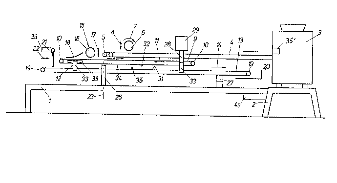
The apparatus has a base frame 1 which simultaneously constitutes a
base 2 for a head machine 3 that divides a bigger lump of dough into dough
portions destined for the production of baked articles. Preferably, these
dough portions are also kneaded in the head machine 3. The portioned dough
pieces are laid by the machine 3 onto deliver bands 4, only two of which are
shown in the drawing for simplification's sake, however, in practice more of
lû such deliver bands 4 may be p,rovided adjacent each other. These endless
running deliver bands may be disposed in a divergent manner in a horizontal
direction away from the head machine 3. Those ends 5 of the bands 4 that do
not face the head machine 3 are preferably staggered or offset relative to
each other in longitudinal direction of the bands and the amount of this
staggered arrangement or, respectively, the position of the ends 5 may be
adjustable by a suitable adjustment means 35' known per se. A flattening
member 6, for example a pressure roller, is bearingly supported on the
base frame 1 above the bands 4 and is driven for rotation in direction of
the arrow 7. The vertical position of this flattening member 6 may be
adjusted by suitable means 36 in direction of the double arrow 8 in order to
enable one to vary the flattening of the dough pieces. At the ends 5 of
the deliver bands 4, the already somewhat flattened dough pieces are
delivered to a first running endless band 9 w ~ h may be an usual conveyor
belt and is driven for run around rollers 10 in direction of the arrow 11.
The rollers 10 and, if desired, further guide means for the band 9 are
bearingly supported in a frame 12 that simultaneously constitutes a similar
frame for a second similar band 13 disposed below the first band 9 and being
driven for run in direction of the arrow 14. This direction 14 of the
` . 2~7~8
- 6 -
band 13, therefore, is the same as that of the lower run 32 of the band 9. A
flattening station 15 is mounted on the frame 12 above the band 9, preferably
in Form of a pressure roller 16, the vertical position of which may be
adjustable by suitable means 37 in direction of the double arrow 17 in order
to adjust the flattening effect on the dough pieces running below this
pressure roller 16. Behind this flattening station 15 (seen in direction of
travel of the dough pieces), a drag band 18 is connected to the frame 12,
preferably in form of a chain band or the like that slides on the dough
pieces running below the drag member 18, so that the dough pieces are
rolled, if such a rolling effect is desired. If not, the drag band 18 is
correspondingly lifted or taken off. At that roller lû of the first endless
running belt 9 that does not face the head machine 3, the dough pieces are
thrown from this band 9 onto the band 13 that is disposed below and as a
rule extends parallel to the band 9. This second band 13 conveys the dough
pieces back in direction towards the head machine 3. The roller 19 of this
band 13 that faces the head machine 3 is disposed above a drawer 20
slidingly guided in the frame 12 and the dough pieces are thrown by the band
13 onto this drawer 20. The latter mentioned roller 19 of the band 13 is so
disposed that the lower band 13, seen from above, protrudes beyond the upper
band 9 so that delivering up of the dough pieces from the band 9 onto the
band 13 is possibly without any problem. In order to ensure this deliver-up,
a correction flap 21 may be mounted on the frame 12, which flap is
preferably adjustable by suitable means 38, the adjustment direction being
indicated by a double arrow 22.
The frame 12 that carries the two belts 9,13 can be swivelled by
hand with respect to the base frame 1 in horizontal direction around a
vertical axis 23 so that that end of the band 13 that neighbours the head
machine 3 is brought into the reaching area of the hands of the operator who
~070028
- 7 -
stands at the front side 24 of the head machine 3 at the place 25 marked
with a cross. For this, the frame 12 is connected to a swivel bearing 26
that is fixed to the base frame 1. This swivel bearing 26 is disposed at the
front side of the base frame 1 or, respectively, of the frame 12, that
means, on that side at which the operator stands at the place 25. The
maximum swivel angle d~ at which the two belts 9,13 can be swivelled with
respect to the longitudinal direction of the conveyor belts 4, amounts to
about 30 (Fig.2). In order to relieve the swivel bearing 26 of the load,
the end of the frame 12 neighbouring the head machine 3 is abutted on the
base frame 1 by means of a telescopic rail 27. At the same time, this
telescopic rail 27 constitutes also a stop for the said swivel motion.
The upper endless running belt 9 may be mounted in the frame 12 in
an adjustable shiftable manner by means 39 in the sense of the double
arrow 34 with respect to the lower endless running belt 13. The speed of
this upper endless running belt 9 can be so chosen that this speed either is
equal to the speed of the lower endless running belt 13, or is different
from that. If desired, the difference of the two speeds may be adjustable
by any suitable means 40. The two belts 9,13 constitute together a further
device 35 that acts on the dough pieces so that their shape is changed. If
the speed of the two bands 9 and 13 is equal, a flattening of the dough
pieces conveyed on carrying run 31 of the lower band 13 back towards the
head machine 3 is obtained, provided that the level of the upper running
endless belt 9 is suitably chosen with respect to the lower endless running
belt 13. If however, the speeds of the two bands 9,13 is chosen differently,
a rolling effect on the dough pieces carried by the band 13 is obtained -
also provided that the relative level of the two bands 9,13 is suitably
chosen. As a rule, one makes the speed of the upper band 9 to be less than
that of the lower band 13, however, the said rolling effect can also be
~ 2~7~02~
By the said staggered disposal of the ends of the conveyor belts 4
that do not face the head machine 3, the transition of the dough pieces from
the bands 4 to the upper endless running belt 9 occurs at different moments,
particularly then if the output of the dough pieces from the head machine 3
is effected in rows directed perpendicularly to the running direction of the
bands 4. By the said oblique position of the endless running belt 9 with
respect to the longitudinal direction of the conveyor belts 4 and by the
adjustable speed of the endless running belt 9, the disposition of the dough
pieces on the band 9 after the deliver-up from the bands 4 can be adjusted
at choice so that the distance of the dough pieces from each other can be
increased what is of advantage in connection with rolling the dough pieces.
The said oblique position of the two bands 9,13 with respect to the
longitudinal direction of the delivery conveyors 4 is the working position
of the operator. If desired, the angle CC can be adjusted at choice. In
order to save space when the machine is not in use, the frame 12 together
with the belts 9,13 carried by it can be swivelled back around the axis 23
so that the longitudinal direction of the two belts 9,13 extends parallel to
the longitudinal direction of the transfer conveyor belts 4. This rest
position is shown in Fig.2 by dotted lines, the working position, however,
is shown by full lines.
The frame 12 carries on its front side a column 28 that extends
sidewise of the belt 9. To this column 28 a flouring means 29 is fixed that
extends above the upper endless running belt 9 and py which the carrying run
of the endless running belt 9 can be sprinkled with flour before putting the
dough pieces onto this belt. The said disposition of the column 28 carrying
the flouring means on one side of the belts 9,13 only enables one to swivel
the band 9,13 into their rest position without that at first the delivery
conveyors 4 must be dismounted. In this rest position the column 28 extends
~ 207~28
g
sidewise of the delivery conveyor belts 4 and the flouring means 29 is
disposed above these belts.
In order to obtain a sufficient distance for what the end of the
band 13 neighbouring the head machine 3 can be swivelled, the swivel bearing
26 is suitably fixed to that half of the frame 12 that is more spaced apart
from the head machine 3. The telescopic rail 27, however, is by static
grounds disposed near the head machine 3 and is suitably pivotally connected
at its both ends with the frame 12 or, respectively, with the base frame 1.
If desired, it is possible to make only the lower belt 13
swivellable around the vertical axis 23 and to make the upper belt 9 fix.
This, however, would shorten the region in which the dough pieces can be
worked between the two belts 9,13 so that the said swivel arrangement of
both belts 9,13 is more favourable.
The motors 30 for driving the belts 9,13 as well as for driving the
flattening station 15 are suitably fixed laterally to the frame 12 and are
swivellable together with this. The entire machine is provided with a
computer control that calls in the corresponding desired programs.
In case of the use of a drawer 20, the removal of the readily formed
dough pieces is made by hand, however, the delivery from the lower endless
running belt 13 can also be directed to a conveyor belt, if desired, to a
further machine, for example a proving compartment or a baking oven.
Instead of the flattening member 6 and/or instead of the flattening
station 15 also other stations may be provided for forming or, respectively,
processing of the dough pieces, for example dough shaping rollers, stamping
means and the like. However, at the said places also no processing of the
dough pieces may occur, for example by removal or by corresponding lifting
of the stations 6,15 so that then the dough pieces delivered from the head
machine 3 onto the belts 4 are processed by the two endless running belts
` ~ 2070~2~
-- 10 --
only. In such a manner for example rolling of round-kneaded dough pieces can
be obtained. The machine, however, can also be operated in such a manner
that the relative distance between the two endless running belts 9,13 is
chosen so great that the dough pieces that are conveyed by the carrying run
31 of the lower endless running belt 13 are no more engaged by the lower run
32 of the upper endless running belt 9. The height level adjustment of the
upper endless running belt 9 necessary for this and for adjustment of the
desired flattening degree can easily be effected by a suitable adjustment
means 33 mounted within the frame 12. This adjustment means, for example,
may comprise excenters by which the relative distance between two frames can
be varied which carry the rollers 10 or, respectively, 19 for the two belts
9 or, respectively, 13.