Note: Descriptions are shown in the official language in which they were submitted.
2070186
-
DESCRIPTION
The present invention relates to a conveyor for
transporting lasagne and similar, flat forms of pasta
through a drier, including at least one pair of
parallel chains which are supported and driven by
respective sprockets along a path extending through the
drier from a station for the loading of the fresh pasta
to a station for the discharge of the dried pasta, and
a plurality of containers for the lasagne, the
containers being arranged transversely between the
chains and removably associated therewith for
transportation along the path.
It is well known that, during the production of dry
pasta, the drying is the most important stage and the
most awkward to carry out. In fact, it is closely
linked and correlated with the organoleptic
characteristics of the pasta produced, its hygienic
qualities and, not least, its preservability, that is,
its shelf life. It is also known that good drying can
even improve the aforementioned characteristics in
comparison with those which can be expected solely on
the basis of the ingredients used to produce the
starting dough.
The success of a dried pasta, and not only its
commercial success, can be attributed essentially to
the drying stage, the techniques used and the manner in
which it is carried out.
From this point of view, the continual care taken to
improve the technique and the means of drying fresh
207QI86
pasta is perhaps taken for granted.
Amongst the variables which add to the complexity of an
investigation into the best manner of and means for
effecting the drying are the shape of the pasta to be
dried and the manoeuvrability of such a shape during
the drying.
Thus, up to now, in the case of, for example, lasagne,
the best drying technique provides for the lasagne to
pass through the drier lying on flat cloths or wide
supporting trays in a single layer so that both of
their faces are exposed to the heat-flow to an equal
extent.
As is known, because the lasagne lie flat, and also
because the heat treatment to which they are subjected
is gentle, the lengths of the driers are generally such
as to constitute a problem from the point of view of
the useful, and hence expensive, space that they take
up .
Moreover, the driers generally have suitable heating,
temperature-control and humidity-control devices which
are distributed along the drier and are operated so as
to achieve experimentally-predetermined temperature and
humidity curves throughout the lengths of the driers,
in order to dry the fresh pasta in an optimal-manner.
The temperature curves are closely linked to the times
for which the lasagne remain in the driers.
The temperature curve selected, the time taken, the
fact that the lasagne lie flat on the cloths or trays,
and the hourly production rate (which must at least be
acceptable from a commercial point of view) mean that
2070186
it is necessary to produce and use very bulky and, in
particular, very long driers.
The space taken up, the high costs of production,
operation and maintenance, and the difficulty of
controlling the temperature and humidity in the drier
are the most readily apparent problems related to the
considerable lengths of the driers which up to now have
been used at an industrial level.
The problem upon which the present invention is based
is that of providing a conveyor for transporting
lasagne and similar forms of pasta through a drier
which has structural and functional characteristics
such that the dimensions and, in particular, the length
of the drier are substantially smaller than those of
conventional driers, without involving changes to the
drying process and, what is more, without affecting the
quality of the dried product (pasta).
According to the invention, the problem is solved by a
conveyor of the type in question which has the
characteristics described in the following claims.
The advantages and characteristics of the invention
will become clearer from the following description of
an embodiment of a conveyor according to the invention
with reference to the appended drawings, which are
given by way of non-limiting example.
In the drawings:
Figure 1 shows schematically a drier using a lasagne
conveyor according to the invention,
2070186
-
Figure 2 shows a drying chamber of the drier of Figure
1 on an enlarged scale and in cross-section,
Figure 3 is a partially-sectioned perspective view of a
lasagne container-support of the conveyor of the
invention, on an enlarged scale,
Figures 4 and 5 show structural details of the
containers of Figure 3, in perspective and on an
enlarged scale,
Figure 6 is a partially-sectioned, perspective view
showing the same detail as Figure 4 from the interior
of the lasagne container-support, on an enlarged scale,
Figure 7 is a side view of the same detail as Figure 6,
Figures 8 and 9 show, in perspective and schematically,
certain arrangements of the container of Figure 3 at
the output and at the input of the drier of Figure 1,
respectively.
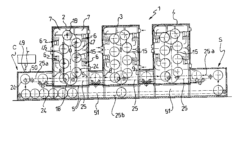
With reference to the drawings, a drier for pasta in
general and for lasagne and similar forms of pasta in
particular is schematically and generally indicated 1.
According to an embodiment which is preferred but
not therefore exclusive, the drier 1 is of the type
including a plurality of structurally independent
drying chambers 2, 3 and 4 aligned and spaced apart on
a base 5.
Such a drier is described fully in the copending
Italian patent application No. MI9lA001114 which was
filed on 23rd April 1991 in the name of the present
2070186
-
Applicant and is included herein for reference. A corresponding
Canadian application entitled "A DRIER FOR PASTA", filed 20
March, 1992, is pending.
The drying chambers 2 to 4 are preferably all the same
and are all similarly equipped, that is to say, they
are modular chambers and, in the following description,
reference will therefore be made to only one chamber,
unless otherwise stated.
Each drying chamber has conventional internal
regulation means 6, 7, not shown in detail, for
controlling and monitoring all the factors which affect
the pasta-drying process, particularly the temperature,
the relative humidity, the pressure, etc., as well as
devices for admitting steam, air and anything else
required to achieve and maintain climatic-ambient
conditions which are predetermined in accordance with a
preferred pasta-drying curve.
At the bottom of each drying chamber is a pasta-inlet
port 8 and a pasta-outlet port 9 which can be closed
hermetically by conventional gates, not shown,
operated, for example, pneumatically, in known manner.
With reference to Figure 2, a vertical conveyor 15
installed in each of the drying chambers 2 to 4 is
preferably endless and of the type including two
parallel, spaced-apart chains 16, 17 driven by
respective sprockets 18, 19 and 20, 21. The sprockets
18, 20 are both keyed to the same shaft 22 which
extends in correspondence with the pasta inlet and
outlet ports and is driven by a motor 23 which is
supported outside the drying chamber in question.
Container-supports for the lasagne to be treated
thermally in the drying chambers are associated
2070186
removably with corresponding links of opposed chains
16, 17. Between the drying chambers 2 to 4 is a
further chain conveyor 25 (Figure 1) which, when
required, can take a container-support 24 from a
conveyor 15 of one chamber and transfer it to the
conveyor 15 of the next chamber.
With reference to Figure 3 and the subsequent drawings,
each of the container-supports 24 includes essentially
a pair of discs 26, 27 keyed to opposite ends of a
hollow shaft 28 which in turn is rotatable on a pin 29
extending axially through the shaft.
The discs 26, 27 are also interconnected by a plurality
of stiffening bars 30 (Figure 5) spaced evenly at
predetermined intervals around the peripheries of the
discs, near their edges. Short portions 30a of the
bars 30 project outwardly of the discs 26, 27.
The bars 30,which make the container-support 24 look
substantially like a cylindrical cage, are preferably
constituted by L-shaped profiles fixed to the discs 26,
27 in an arrangement such that one flange of each is
oriented radially and their other flanges are all
oriented in the same sense, for example, clockwise.
In correspondence with each of the bars 30, the discs
26, 27 have respective coplanar projections 31, 31a
with flattened points, extending radially from the
circular edges of the discs and connected suitably
thereto.
The end of a rectangular, flat spring 32 is fixed to
the other flange of the portion 30a of each bar 30
outside the discs 26, 27 and its other, free end bears
2070186
on the portion 30a of an adjacent bar 30.
In particular, and with reference to Figure 5, the
springs 32 are arranged in a circle substantially
coaxial with the discs 26, 27, the free end of each
spring in the circle being superposed and bearing on
the fixed end of the preceding spring. Each spring 32
includes a longer, inclined portion 32a and a curved,
substantially spoon-shaped portion 32b which opens
outwardly of the discs 26 and 27 and constitutes the
free end of the spring. It should be noted that the
substantially spoon-shaped, curved portions 32b are
positioned in correspondence with the pointed
projections 31, 31a of the discs 26, 27.
A first plurality of rectangular cloths 33 is supported
between the discs, the cloths being disposed radially
and equiangularly spaced at the centre. Each cloth 33
is stretched between a corresponding bar 30 and the
shaft 28. For this purpose, opposite sides of the
cloth 33 have respective hems 33a, 33b.
The hem 33a is fitted onto a respective bar 30 and a
rod 34 (Figure 6), which is intended to be engaged
removably in a corresponding longitudinal seat 35 in
the shaft 28, is fitted (threaded) through the other
hem 33b.
In particular, and according to a preferred embodiment,
the shaft 28 has a plurality of recesses 36 with
circular internal portions of which the diameters are
larger than the widths of the recesses themselves and
which constitute the seats 35.
A second plurality of cloths 37 (Figures 6 and 7) is
2070186
-
supported between the discs 26, 27, each cloth being
associated with a corresponding cloth 33 so as to form
a pocket (T) for housing the pasta (lasagne) to be
dried, as will become clearer from the following
description.
One side of each cloth 37 is parallel to the shaft 28
and has a hem 37a in which a cylindrical rod 38 is
fitted, the rod 38 having end portions 38a, 38b (Figure
3) which are outside the hem 37a and bear on
corresponding opposed springs 32.
The side of the cloth 37 opposite and parallel to that
with the hem 37a is sewn, or otherwise fixed throughout
its length, to the cloth 33 at a predetermined distance
from the shaft 28. Each cloth 37 is stretched so that
the rod 38 bears against the respective opposed springs
32 of the discs 26, 27 with a predetermined force.
If the cylindrical rod 38 is moved from one end of each
of the springs 32 on which it is engaged to the other,
the cloth 37 is moved angularly from a position in
which it is spaced from the cloth 33 (in which the
pocket is open) to a position in which it is closer to
and substantially beside the cloth 33 (and in which the
pocket is closed).
To advantage, in the latter position (in which the
pocket is closed) the opposite ends 38a, 38b of each
cylindrical rod 38 are engaged in the curved
spoon-shaped ends of the springs 32 of the opposed
discs 25, 26. In this position, the rods 38 are
further positively retained since they bear against the
pointed projections 31, 31a of the discs, which
constitute effective stops for preventing the rods 38
- 2070186
.
from being released in the wrong direction, as will
become clearer from the following description.
Corresponding gears 44, 45 are fixed coaxially to the
outer walls of the discs 26, 27 for engaging respective
racks 46, 47 which extend beside the chains 16, 17
along predetermined portions of the path which the
containers-supports 24 have to follow through the drier
of the invention.
In particular, and in the case of the multi-chambered
drier described above, the racks 46, 47 extend in
correspondence with the vertical portions of the
conveyors 15 in the individual drying chambers.
As a result of this engagement, the container-supports
24 are forced to roll as they move along the path.
The drier 1 of the invention includes a station C
immediately upstream of the first drying chamber 2 for
the loading of the lasagne to be dried, and a station S
immediately downstream of the last drying chamber 4 for
discharging the dried pasta.
In order to load the lasagne to be dried into each of
the container-supports 24, the normally-closed pockets
formed by the cloths 33 and 37 have to be opened in
succession. In the former condition (in which the
pockets are closed) the rods 38 which support the
cloths 37 are restrained in the spoon-shaped free ends
32b of the springs 32 with the cooperation of the
rounded sides of the respective peripheral, pointed
projections 31 of the discs 26, 27.
In order to open the pockets, the rods 38 therefore
2070186
have to be disengaged from the spoon-shaped ends 32b
and then moved along the inclined portions 32a of the
springs 32 to their fixed ends, against the
corresponding pointed projections 31.
The open pockets are closed by carrying out these
movements of the rods in reverse.
A pair of devices, generally indicated 39 and 40 in
Figures 6 and 7, is used for moving the rods 38 along
the springs 32.
Each of these devices includes essentially a lever 41
which pivots on a support 42 with its pivoting axis
parallel to the axis of the shaft 28 and has a
fork-shaped operative end 41a for engaging a
corresponding portion 38a or 38b of a cylindrical rod
38. The powered end 41b of the lever 41 is driven by
a pneumatic cylinder 43 supported by the support 42
mentioned above.
As described above, the lasagne are loaded into the
container-supports 24 in the station C. For this
purpose, when the container 24 is in the position
indicated 24a, the top vertical pocket which is
aligned, for example, with a lasagne-loading aperture
49 in the top 50 of the loading station C (Figure 1) is
opened.
Two racks 52, 53 (Figure 9), which extend horizontally
in order to engage the gears 44, 45 of the container
24, are used in the station C for positioning the
container 24 angularly in order to position each of its
pockets in the vertical lasagne-loading position. The
racks 52, 53, which are driven by a brushless motor 54,
- _ 2070186
are guided vertically in known manner, not shown.
A strip of rolled pasta dough L (a lasagna) is loaded
(for example, inserted) into the open pocket from above
as it leaves a device known as a lasagna-making machine
which is well known and is therefore not described
herein since it is irrelevant for the purposes of an
understanding of the present invention.
At this point, the pocket is closed and the
container-support 24 in question is rotated through an
angle such as to bring a new, closed pocket to the
vertical position, a new sheet of lasagna to be dried
being inserted in the new pocket after it has been
opened in the manner already described.
When all the pockets of a container-support 24 have
been filled with respective strips of rolled pasta
dough S, the container 24 is taken by a conveyor 25a
(just like the conveyors 25 between one drying chamber
and another) and transferred to the first drying
chamber 2. In this drying chamber, the container is
picked up by the ascending pass of the conveyor 15 in a
known, conventional manner, not shown, in order to
perform one or more circuits within the drying chamber
2. As it travels upwards, and as it travels downwards
on the other pass of the same conveyor 15, the gears
44, 45 of the container support 24 engage the
respective racks 46, 47 so that the container-support
24 rolls as it moves along the conveyor 15.
After one or more circuits on the conveyor 15 of the
first drying chamber (the number of circuits depends
upon the predetermined period to be spent by each
container 24 in the chamber) the container is withdrawn
12 2070186
by the conveyor 25 and transferred to the next drying
chamber 3. When it is discharged from the last drying
chamber 4, the container-support 24 with the fully
dried lasagne is transferred to the unloading station S
in which the steps already described for loading the
fresh lasagne to be dried are carried out in reverse
with the use of a set of motor-driven racks the same as
those shown in Figure 9 and a similar device-(39-40)
for opening and closing the pockets of the containers
24.
In particular, in the station S, the lasagne fall from
the preselected pockets onto a corresponding chute 55
(Figure 8) from which they are passed onto a vibrating
table 56 of the saw-toothed type for aligning the
lasagne.
The empty containers from which the dried lasagne have
been removed are returned to the loading station C.
To advantage, a further conveyor 25b extending along a
tunnel 51 which, to advantage, is formed in the base 5
of the drier 1 of the invention is used for this
purpose.