Language selection

Search

Patent 2070430 Summary

Third-party information liability

Some of the information on this Web page has been provided by external sources. The Government of Canada is not responsible for the accuracy, reliability or currency of the information supplied by external sources. Users wishing to rely upon this information should consult directly with the source of the information. Content provided by external sources is not subject to official languages, privacy and accessibility requirements.

Claims and Abstract availability

Any discrepancies in the text and image of the Claims and Abstract are due to differing posting times. Text of the Claims and Abstract are posted:

  • At the time the application is open to public inspection;
  • At the time of issue of the patent (grant).
(12) Patent: (11) CA 2070430
(54) English Title: URINARY CONTROL WITH INFLATABLE SEAL
(54) French Title: DISPOSITIF DE CONTROLE URINAIRE AVEC JOINT GONFLABLE
Status: Expired and beyond the Period of Reversal
Bibliographic Data
(51) International Patent Classification (IPC):
  • A61F 02/00 (2006.01)
  • A61F 05/453 (2006.01)
  • A61F 05/455 (2006.01)
  • A61M 25/10 (2013.01)
(72) Inventors :
  • SALAMA, FOUAD A. (United States of America)
(73) Owners :
  • OPTICON MEDICAL INC.
(71) Applicants :
  • OPTICON MEDICAL INC. (United States of America)
(74) Agent: SMART & BIGGAR LP
(74) Associate agent:
(45) Issued: 1995-11-07
(86) PCT Filing Date: 1991-09-03
(87) Open to Public Inspection: 1992-04-23
Examination requested: 1994-01-05
Availability of licence: N/A
Dedicated to the Public: N/A
(25) Language of filing: English

Patent Cooperation Treaty (PCT): Yes
(86) PCT Filing Number: PCT/US1991/006228
(87) International Publication Number: US1991006228
(85) National Entry: 1992-06-03

(30) Application Priority Data:
Application No. Country/Territory Date
07/600,629 (United States of America) 1990-10-22

Abstracts

English Abstract


A urine tube (12) extends through a balloon (26) which is inflatable in the
neck of a bladder (38) to form a seal around the urine tube (12). The balloon (26)
has a shape corresponding to the shape of the bladder chamber at the urethra or-ifice (38) to facilitate establishing a seal. A valve (14) is provided on the outlet
end (15) of the urine tube (12) and an air tube (20) extends along the substantial
length of the urine tube (12) into the balloon (26). A hypodermic syringe (48) or
the like may be inserted into the inlet end (22) of the air tube (20) for inflating
the balloon (26). A hydrogel collar (36) is positioned around the urine tube (12)
against the body (40) at the outlet end of the urethra to hold the balloon (26) in
tight engagement with the bladder neck (38) at the urethra orifice.


Claims

Note: Claims are shown in the official language in which they were submitted.

The embodiments of the invention in which an exclusive
property or privilege is claimed are defined as follows:
1. A urethral catheter for controlling a flow of urine from
a bladder through a urethra of a person, said bladder having
an interior, a neck region, and an orifice fluidly
communicating with said urethra, said urethral catheter
comprising: a urine tube, said urine tube having an
exterior; and an inflatable balloon, said inflatable balloon
being connected to said urine tube, said inflatable balloon
having an interior, said urine tube extending through said
interior of said inflatable balloon and fluidly communicating
with the interior of the bladder, said inflatable balloon
having a generally non-spherical shape including an upper
portion and a lower portion, said upper portion being
generally larger than said lower portion, said lower portion
of said inflatable balloon being sized so as to be received
at least partially within the urethra generally proximate to
the neck region and the orifice of the bladder to form a plug
seal within the urethra when said inflatable balloon is
inflated and said upper portion of said inflatable balloon is
seated within the interior of the bladder contacting the
bladder closely proximate to the neck region and the orifice,
whereby the plug seal formed by the inflatable balloon within
the urethra prevents the flow of urine from within the
bladder through the urethra on the exterior of the urine
tube.
2. The urethral catheter of claim 1 wherein the urine tube
includes a valve for selectively preventing the flow of urine
through the urine tube.
3. In a urethral catheter for controlling a flow of urine
from a bladder through a urethra of a person, said bladder
having an interior, a neck region, and an orifice fluidly
communicating with said urethra, said urethral catheter
including a urine tube and an inflatable balloon connected to
said urine tube, said urine tube having an exterior and said
inflatable balloon having an interior, said urine tube
extending through said interior of said inflatable balloon

and fluidly communicating with said interior of said bladder,
the improvement comprising: the inflatable balloon having a
generally non-spherical shape including an upper portion and
a lower portion, said upper portion being generally larger
than said lower portion, said lower portion of the inflatable
balloon being sized so as to be received at least partially
within the urethra generally proximate to the neck region and
the orifice of the bladder to form a plug seal within the
urethra when the inflatable balloon is inflated and said
upper portion of the inflatable balloon is seated within the
interior of the bladder contacting the bladder closely
proximate to the neck region and the orifice, whereby the
plug seal formed by the inflatable balloon within the urethra
prevents the flow of urine from within the bladder through
the urethra on the exterior of the urine tube.
4. The urethral catheter of claim 1 wherein an anchoring
member is operatively connected to the urine tube for
maintaining the lower portion of said inflatable balloon
closely adjacent to the neck and orifice of the bladder and
within the urethra.
5. The urethral catheter of claim 1 wherein an anchoring
member is connected to the urine tube for operative
engagement with the body member adjacent to the distal end of
the urethra to seat the downwardly depending lower end
portion of the inflatable balloon closely adjacent to the
neck and the orifice of the bladder and within the urethra.
6. The urethral catheter of claim 5 and a support shell for
generally surrounding the penis, said support shell having a
distal end and an inner surface, the outlet end of the urine
tube extending outwardly beyond said distal end of said
support shell with the anchoring member being in operative
engagement with said distal end of said support shell, said
inner surface of said support shell operatively engaging the
penis generally proximate to the distal end thereof; and said

anchoring member providing resistance when pulling the
inflatable balloon downwardly for seating the inflatable
balloon by pulling the inflatable balloon downwardly toward
the neck and the orifice of the bladder.
7. The urethral catheter of claim 1 wherein the urine tube
is a flexible, longitudinally collapsible urine tube such
that longitudinal compressive pressure applied to the urine
tube will not unseat the downwardly extending reduced-in-size
portion of the inflatable balloon from within the urethra and
cause leakage on the exterior of the inflation tube or the
exterior of the urine tube.
8. The urethral catheter of claim 1 wherein the urine tube
is fabricated from an elastomeric silicone material.
9. The urethral catheter of claim 1 wherein the inflatable
balloon has a volume, said volume being generally less than
or equal to 40 cc.
10. The urethral catheter of claim 1 wherein a collar
encircles the urine tube and the inflation tube for being
positioned in operative engagement with a person's pubic bone
to thereby limit longitudinal movement of the urine tube and
the inflation tube into the bladder.
11. The urethral catheter of claim 2 wherein an anchoring
member is operatively connected to the urine tube for
maintaining the lower portion of said inflatable balloon
closely adjacent to the neck and orifice of the bladder and
within the urethra.
12. The urethral catheter of claim 2 wherein an anchoring
member is connected to the urine tube for operative
engagement with the body member adjacent to the distal end of
the urethra to seat the downwardly depending lower end

portion of the inflatable balloon closely adjacent to the
neck and the orifice of the bladder and within the urethra.
13. The urethral catheter of claim 12 and a support shell
for generally surrounding the penis, said support shell
having a distal end and an inner surface, the outlet end of
the urine tube extending outwardly beyond said distal end of
said support shell with the anchoring member being in
operative engagement with said distal end of said support
shell, said inner surface of said support shell operatively
engaging the penis generally proximate to the distal end
thereof; and said anchoring member providing resistance when
pulling the inflatable balloon downwardly for seating the
inflatable balloon by pulling the inflatable balloon
downwardly toward the neck and the orifice of the bladder.
14. The urethral catheter of claim 2 wherein the urine tube
is a flexible, longitudinally collapsible urine tube such
that longitudinal compressive pressure applied to the urine
tube will not unseat the downwardly extending reduced-in-size
portion of the inflatable balloon from within the urethra and
cause leakage on the exterior of the inflation tube or the
exterior of the urine tube.
15. The urethral catheter of claim 2 wherein the urine tube
is fabricated from an elastomeric silicone material.
16. The urethral catheter of claim 2 wherein the inflatable
balloon has a volume, said volume being generally less than
or equal to 40 cc.
17. The urethral catheter of claim 2 wherein a collar
encircles the urine tube and the inflation tube for being
positioned in operative engagement with a person's pubic bone
to thereby limit longitudinal movement of the urine tube and
the inflation tube into the bladder.
11

Description

Note: Descriptions are shown in the official language in which they were submitted.


- 1- 2070430
URINARY CONTROL WITH INFTA~ART~ SEAL
BACKGROUND OF THE INVENTION
Incontinence is a problem for many people,
including older adults. Present day approaches to
dealing with incontinence such as the Foley catheter
often times cause urinary tract infection. A bag for
urine is required and smell becomes a problem. The
chances of infection are increased each time the bag
is changed. The cost for the Foley catheters and bags
is substantial. An inflatable conventional spherical
balloon is used to keep the catheter in the bladder,
but leakage around the catheter occurs and is a
problem. It was not an object of this product to
provide a seal around the catheter at the bladder
orifice.
I have disclosed a urethral valve positioned in
the orifice of the urethra. In some instances,
leakage may occur around the outside of the valve.
What is needed is a simple inexpensive device for
controlling urine flow in the urethra which is
compatible to the body and will not cause discomfort
or infection, and pass urine only through operation of
the valve rather than around the outside of the
catheter.
X

2070430
SUMMARY OF THE lNV~;N'l'lON
A urinary tube extends into the urethra and
continues into the bladder. An inflatable balloon
having a lower end portion extending into the urethra
has a shape corresponding to the shape of the inner
wall surface of the bladder at the orifice, extends
around the bladder end of the urinary tube and an air
line extends through the urine tube to outside the
urethra where it is adapted to be connected to an air
pump for inflating the balloon to provide a plug seal
in the urethra around the urinary tube in the neck and
orifice of the bladder. A valve is provided in the
urinary tube outside of the urethra.
An anchoring collar of hydrogel frictionally
engages the exterior of the urinary tube and is
positioned against the outer end of the urethra to
hold the balloon lower end portion in tight sealing
engagement in the urethra in the neck of the bladder.
The urinary control of this invention when used
by a male includes the additional use of a support
shell around the penis to stabilize the urinary tube
which extends through the penis. The anchoring collar
of hydrogel is positioned against the outer end of the
support shell. The shell is one piece but includes a
plurality of sections to allow for fitting the support
shell to penises of different sizes. A collar of
hydrogel is also placed between the inner and of the

2070430
shell sections and the pubic bone base of the penis.
An accordion type section is included to give the
shell flexibility in accommodating penises of
different lengths and to permit them to be disposed at
varying angles to the body.
A hypodermic syringe or the like may function as an
air pump when its needle is inserted into the air tube
to inflate the balloon.
DESCRIPTION OF THE DRAWINGS
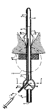
Figure 1 is a fragmentary perspective view of the
urinary control with inflatable seal.
Figure 2 is a longitudinal cross-sectional view of
the urinary control in the urethra of a female.
Figure 3 is an enlarged cross-sectional view of the
structure indicated by the line 3 - 3 in Figure 2.
Figure 4 is a cross-sectional view taken along line
4 - 4 in Figure 2 showing the valve in a closed
condition.
Figure 5 is a view similar to Figure 4 but showing
the valve in an open condition.
Figure 6 is a view similar to Figure 2 but showing
the urinary control in the urethra of a male.

2070430
DESCRIPTION OF THE PREFERRED EMBODIMENT
The urinary control of this invention is referred
to generally by the reference numeral 10 as seen in
Figure 1 and includes a urine tube 12 in which a valve
14 is connected. The tube 12 has an outer outlet end
15 and an inner inlet end 16 with sidewall openings
18.
An air tube 20 extends into the valve body 14 and
along the length of the tube 12 towards the inlet end
16. The air tube 20 has an inlet end 22 and an outlet
end 24 positioned in a balloon 26 formed in part by
the sidewalls of the urine tube 14. Balloon chamber
28 is provided. The air tube outlet end includes an
opening 30 in chamber 28.
The valve body 14 includes a pair of oppositely
disposed blade elements 32 normally closed. Pressure
on the opposite sidewalls of the valve body 14 will
cause the valve elements 32 to spread as seen in
Figure 5 and allow urine to flow toward the outlet end
14.
An anchoring collar means 36 of hydrogel is
provided around the urine tube 12 outwardly of the
balloon 26 and frictionally engages the outer surface
of the urine tube 12 to hold the walls of the balloon
26 in tight sealing contact with the bladder orifice
and neck 38 as seen in Figure 2. The balloon 26 is
shaped to correspond to the shape of the inner

2070430
sidewalls of the bladder at the orifice to provide a
seal around the catheter thereby preventing leakage.
This shape is generally pear shape. As seen in
Figures 2 and 6, the balloon 26 when inflated includes
an enlarged upper portion which merges into a
downwardly extending reduced in size lower portion.
In the female, the collar 36 presses against the body
around the opening to the urethra. A sleeve 42 also
extends around the urine tube 12 and may be adjusted
tightly against the collar 36 to assist in holding the
collar tight against the person's body at the outlet
end of the urethra. Rounded serrations 44 are
provided along the outside of the urine tube 12 and
register with serrations on the inside face of the
collar 36 and serve to hold the collar 36 in place in
turn holding the balloon seal 26 in place thereby
preventing leakage around the tube 12.
A hypodermic syringe 48 functions as an air pump
and has a needle 50 which is inserted into the inlet
end 22 of the air tube 20. The inlet end 22 has a
passageway 52 normally closed except when opened by
the needle 50 thereby allowing air to be introduced
into the tube to fill the balloon 26 but when the
needle 50 is removed the passageway is sealed
preventing air from escaping and deflating the
balloon.

2070430
When the urinary control of this invention is used
on a male, a one piece support shell 60 is provided
around the penis 62 and includes an outer section 64
having an outer end 64A being rounded to the curvature
of the head of the penis. An accordion pleats section
64B interconnects the outer section 64 with a base
section 64C. The base section 64C presses against a
hydrogel collar 66 which presses against the base
(public bone) 68 of the penis. A second hydrogel
collar 70 is positioned against the outer end of the
rounded section 64A to hold the urine tube 12 in place
such that the lower portion of the balloon 26 when
inflated is pressed against the bladder neck 38 and
into the urethra. Among the properties of hydrogel is
that it is soft and pliable but yet firm.
In use it is seen that the urine tube 12 will be
inserted into the urethra of the male or female far
enough that the upper portion of the balloon 26 will
function as a retention means and the lower portion
will be seated in the urethra at the neck 38 of the
bladder and functions as a plug to prevent urine flow
on the outside of the urine tube 12. Air is
introduced into the air tube 20 through the use of a
hypodermic syringe. A hydrogel collar is then
positioned against the body at the outer end of the
urethra to hold the balloon 26 in position to maintain
the seal in the urethra at the bladder neck 38. The

2070430
balloon is inflated from the solid line position in
Figure 2 to the dash line inflated condition. When
fully installed, no urine can leak around the urine
tube 12 due to the seal the balloon 26 provides in the
urethra at the bladder neck 38. Urine can enter the
openings 18 in the inlet end 16 of the urine tube 12
and pass into the valve 14 and upon actuation of the
valve blades 32 by applying pressure to opposite sides
of the valve 14, the valve will be open for drainage
of the bladder through the outlet end 15.
The valve 14 and urine tube 12 are formed from
elastomer silicone material of a 50 or 55 durometer
from Dow Corning, Midland, Michigan. Tubing of this
material is flexible and longitudinally collapsible
such that longitudinal compressive pressure applied to
it will not unseat the balloon lower portion in the
urethra at the neck and orifice of the bladder and
cause leakage around the tubing. The balloon 26 may
have a capacity of approximately 40 cc's.

Representative Drawing
A single figure which represents the drawing illustrating the invention.
Administrative Status

2024-08-01:As part of the Next Generation Patents (NGP) transition, the Canadian Patents Database (CPD) now contains a more detailed Event History, which replicates the Event Log of our new back-office solution.

Please note that "Inactive:" events refers to events no longer in use in our new back-office solution.

For a clearer understanding of the status of the application/patent presented on this page, the site Disclaimer , as well as the definitions for Patent , Event History , Maintenance Fee  and Payment History  should be consulted.

Event History

Description Date
Inactive: IPC deactivated 2015-08-29
Inactive: IPC assigned 2015-05-13
Inactive: First IPC assigned 2015-05-13
Inactive: IPC removed 2015-05-13
Inactive: IPC expired 2013-01-01
Inactive: Reversal of expired status 2012-12-02
Time Limit for Reversal Expired 2011-09-03
Letter Sent 2010-09-03
Inactive: Late MF processed 2009-10-08
Letter Sent 2009-09-03
Inactive: IPC from MCD 2006-03-11
Inactive: Entity size changed 2003-08-27
Grant by Issuance 1995-11-07
Request for Examination Requirements Determined Compliant 1994-01-05
All Requirements for Examination Determined Compliant 1994-01-05
Small Entity Declaration Determined Compliant 1992-06-03
Application Published (Open to Public Inspection) 1992-04-23

Abandonment History

There is no abandonment history.

Fee History

Fee Type Anniversary Year Due Date Paid Date
MF (patent, 6th anniv.) - small 1997-09-03 1997-08-20
MF (patent, 7th anniv.) - small 1998-09-03 1998-09-03
Registration of a document 1998-09-25
MF (patent, 8th anniv.) - small 1999-09-03 1999-08-31
MF (patent, 9th anniv.) - small 2000-09-05 2000-09-01
MF (patent, 10th anniv.) - small 2001-09-03 2001-08-07
Reversal of deemed expiry 2009-09-03 2001-08-07
MF (patent, 11th anniv.) - small 2002-09-03 2002-08-08
Reversal of deemed expiry 2009-09-03 2002-08-08
MF (patent, 12th anniv.) - standard 2003-09-03 2003-08-05
MF (patent, 13th anniv.) - standard 2004-09-03 2004-08-09
MF (patent, 14th anniv.) - standard 2005-09-05 2005-08-08
MF (patent, 15th anniv.) - standard 2006-09-05 2006-08-08
MF (patent, 16th anniv.) - standard 2007-09-04 2007-08-06
MF (patent, 17th anniv.) - standard 2008-09-03 2008-08-11
MF (patent, 18th anniv.) - small 2009-09-03 2009-10-08
Reversal of deemed expiry 2009-09-03 2009-10-08
Owners on Record

Note: Records showing the ownership history in alphabetical order.

Current Owners on Record
OPTICON MEDICAL INC.
Past Owners on Record
FOUAD A. SALAMA
Past Owners that do not appear in the "Owners on Record" listing will appear in other documentation within the application.
Documents

To view selected files, please enter reCAPTCHA code :


To view images, click a link in the Document Description column. To download the documents, select one or more checkboxes in the first column and then click the "Download Selected in PDF format (Zip Archive)" or the "Download Selected as Single PDF" button.

List of published and non-published patent-specific documents on the CPD .

If you have any difficulty accessing content, you can call the Client Service Centre at 1-866-997-1936 or send them an e-mail at CIPO Client Service Centre.


Document
Description 
Date
(yyyy-mm-dd) 
Number of pages   Size of Image (KB) 
Description 1995-11-06 7 215
Abstract 1995-11-06 1 58
Claims 1995-11-06 4 190
Abstract 1995-11-06 1 58
Drawings 1995-11-06 2 82
Representative drawing 1999-01-05 1 11
Courtesy - Certificate of registration (related document(s)) 1998-10-27 1 114
Maintenance Fee Notice 2009-10-14 1 170
Late Payment Acknowledgement 2009-10-26 1 163
Maintenance Fee Notice 2010-10-17 1 170
Fees 1996-08-21 1 45
Fees 1995-08-30 1 32
Fees 1994-08-24 1 49
Fees 1993-08-31 1 21
Prosecution correspondence 1995-08-30 1 37
Examiner Requisition 1994-10-04 2 71
Prosecution correspondence 1994-01-04 1 21
Prosecution correspondence 1995-01-04 2 67
International preliminary examination report 1992-06-02 2 77