Language selection

Search

Patent 2071062 Summary

Third-party information liability

Some of the information on this Web page has been provided by external sources. The Government of Canada is not responsible for the accuracy, reliability or currency of the information supplied by external sources. Users wishing to rely upon this information should consult directly with the source of the information. Content provided by external sources is not subject to official languages, privacy and accessibility requirements.

Claims and Abstract availability

Any discrepancies in the text and image of the Claims and Abstract are due to differing posting times. Text of the Claims and Abstract are posted:

  • At the time the application is open to public inspection;
  • At the time of issue of the patent (grant).
(12) Patent: (11) CA 2071062
(54) English Title: TRASH CAN LINER
(54) French Title: GARNITURE INTERIEURE DE CONTENANT A ORDURES
Status: Expired and beyond the Period of Reversal
Bibliographic Data
(51) International Patent Classification (IPC):
  • B65F 01/06 (2006.01)
  • B65D 30/08 (2006.01)
  • B65F 01/00 (2006.01)
(72) Inventors :
  • FREEMAN, SCOTT THEODOR (United States of America)
(73) Owners :
  • TENNECO PACKAGING INC.
(71) Applicants :
  • TENNECO PACKAGING INC. (United States of America)
(74) Agent: GOWLING WLG (CANADA) LLP
(74) Associate agent:
(45) Issued: 1999-11-16
(22) Filed Date: 1992-06-11
(41) Open to Public Inspection: 1992-12-18
Examination requested: 1997-03-13
Availability of licence: N/A
Dedicated to the Public: N/A
(25) Language of filing: English

Patent Cooperation Treaty (PCT): No

(30) Application Priority Data:
Application No. Country/Territory Date
716,161 (United States of America) 1991-06-17

Abstracts

English Abstract


A trash can liner is disclosed which evenly distributes the load
across the sealed bottom portion thereof. The liner includes a body
portion which is formed from a tube of coextruded, thermoplastic film.
The tube includes edge portions which are folded inwardly towards the
center line of the tube along first and second fold lines. The tube
is also folded along its center line prior to sealing to form a
construction including eight overlapping walls of approximately equal
width. A pair of heat seals extend through each of the eight
overlapping walls at one end of the tube, the heat seals being
separated by an unsealed area.


Claims

Note: Claims are shown in the official language in which they were submitted.

-6-
WHAT IS CLAIMED IS:
1. A trash can liner comprising;
a body portion formed from a tube of coextruded, thermoplastic film,
the tube being folded along a plurality of longitudinal fold lines to
form at least eight overlapping walls;
said body portion including a closed end, said closed end
including a first heat seal extending transversely across the tube and
formed through all of the overlapping walls of the tube and a second
heat seal extending transversely across the tube and formed through
all of the overlapping walls of the tube, said first heat seal
extending substantially parallel to and adjacent to said send heat
seal, and an unsealed area defined between said first and second heat
seals;
said body portion including an open end opposite from said
closed end.
2. A trash can liner as described in claim 1 wherein said tube
includes first and second edge portions and a longitudinal center
line, said edge portions being folds inwardly towards said
longitudinal center line along first and second fold lines, and said
tube being folded along said center line, whereby said tube includes
eight overlapping walls through which said first and second heat seals
are formed, each of said overlapping walls being substantially equal
in width.
3. A trash can liner as described in claim 2 wherein said coextruded
film includes an outer layer and an inner layer, said outer layer
being a different color than said inner layer.
4. A trash can liner as described in claim 3 wherein at least one of
said layers is comprised of high density polyethylene.
5. A trash can liner as described in claim 4 wherein said inner and
outer layers are both comprised of high density polyethylene.

-7-
6. A trash can liner as described in claim 1 wherein said coextruded
film includes an outer layer an inner layer, said outer layer being a
different color than said inner layer.
7. A trash can liner as described in claim 5 wherein at least one of
said layers is comprised of high density polyethylene.
8. A trash can line as described in claim 7 wherein said inner and
outer layers are both comprised of high density polyethylene.
9. A trash can liner as described in claim 8 wherein said film is
opaque.
10. A trash can liner as described in claim 1 wherein said first and
second heat seals are separated by about one eight of an inch, the
second heat seal being about one quarter inch from an edge of the
tube.

Description

Note: Descriptions are shown in the official language in which they were submitted.


F-62 ~.7-L ( SGC)
_ x
TRASI-I OAI~d LINER
BACKQ20L1NL) Of THE; II3~'20N
1. Field of the invention
The field of the invention relates to bags or sacks which may be used
as liners for trash cans and the like.
2. Brief description of the related art.
Bag-type liners are fr~uently used within trash cans for protecting
the cans and to facilitate removal of the contents therefrcsm. The
materials from which a liner is made and the manner in which it is
constructed depends upon the intended use thereof: Diners intended
for grass clippings and garden debris need not be particularly
leak proof as the consequences of leakage are insignificant. Where
such liners are for ir~lustrial waste) prevention of leakage is
very important, even where the waste is not partticularly hazardous.
Various approaches have been taken for manufacturing arid sealing
liners in order to prevent leakage therefrom. An early form of such
liners was made from an unfolded therefrom. An early form of such
liners was made from an unfolded tube. The entire width of the bottom
of the tube was sear with either a single or a double seal bar.
This construction is referred to as the "lay flat" construction. In
order to seal more bags in production, a gusseted bag has been
produced. The seal across a gusseted bag does not hold up well under
wet load testing, however.
Folded end seal bags have been found to provide a strong seal as the
forces exerted upon the bottom of the bag are relatively uniformly
distributed. Such bags or liners are formed by first folding the two
outside edges of a tube tewards the middle, then folding one resulting
edge over the other. The seal extending across such tags is through
eight layers.

F-6217-L(SGC)
- 2 -
"S~ar seals" are formed by folding the right edge over the left edge
of a tube, and then again folding the right edge over the left edge.
I9~is type of. seal also provides for stress distrixrution.
The presence of wrinkles in thermoplastic fi7.ms, and particularly high
~Iec~zlar weight films, can cause deterioration of the seals at the
bottoms of liners forrc~d from such films. Penetration of the end
seals by such wrinkles can result in leakage. Reduction of the ntunber
of wrinkles is only a partial solution to this problem.
SUNf?ARY OF THE ITIV~ION
It is an object of the invention to provide a trash can liner which is
substantially leakproof.
It is an other object of the invention to provide a trash can liner
having an end seal which resists degradation.
A still further object of the invention is to provide a trash can
liner having superior strength and an attractive appearance. ,
In acxordance with these and other objects of the invention, a trash
can liner is provided which comprises a body portion formed frarn a
tube of coextruded, thermoplastic film, the tube being folded along a
plurality of longi~l fold lines to form at least eight
overlapping walls, a first heat seal sealing an end of the tube arid
formed through all of the overlapping walls of the tube, and a second
heat seal formed through all ~of the overlapping walls of the tube and
extending parallel ark adjacent to the first end seal. The inside and
outside layers of the coextruded film are preferably different in
color. Both layers are preferably high density polyethylene. The
tube is preferably constructed in folded end seal form by folding the
two edges of the tube towar.~is the middle and then folding the entire
tube along its center line. The end seals are then formed through

F--6217-L (SGC)
eight walls of material.
BRIEF' DFSCRIPfION OF THE DRAWINGS
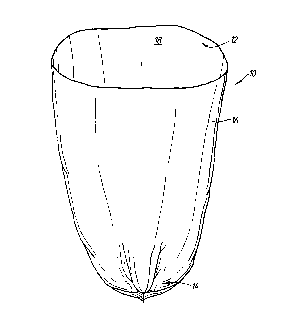
Fig. 1 is a top perspective v9.ew of a trash can liner in acxordance
with the invention;
Fig. 2 is an enlarged sectional view of the closed, bottarn end of the
liner;
Fig. 3 is a greatly enlarged, sectional view taken laterally across
the liner;
Fig. 4 is a top plan view of the sealed bottom end of a folded liner;
and
Fig. 5 is an elevation view of an apparatus for sealing the liner in
accordance with the invention.
DETAILEp DES(~TP'fION OF ~ 1N~7F~FI'IDN
A trash can liner 10 made from a tube of c~extruded film is shown in
Fig. 1. The liner includes an open top end l2 and a sealed bottom end
14. As the film is coextruded, the outer surface layer 16 may be made
fraln a different material than the inner surface layer 18. The two
layers are preferably of different ~lors whether made from the same
ox different materials. In a preferred embc~ditt~nt of the invention,
each of the layers is manufactur~l from a virgin high molecular weight
resin such as high density polyethylene (I~PE). Each layer is
preferably opaque.
The tube from which the liner is made is folded in the manner shim in
Fig. 3 prior to sealing the bottom end thereof. First and second
folds 20,22 are made as the opposing edges of the -tube are folded
inwardly. The tube is then folded along its center line 24. a total
of eight coextruded walls are accordingly arranged in stacked
relation, as shown in Figs. 2 and 3. Each of the walls is
substantially equal in widths as shown in Fig. 3. The wall thickness
is up to about one mil.

F-6217-L(SGC}
_ 4
The tube, as folded an the manner shown in Fig. 3, is passed
through a sealing station 26 as shown in Fig. 5, The station 26
includes a seal blade 28 including first. and second sealing edges 28A,
28B. Each ~lge has a width of about one s:i.xteenth of an inch. The
leading and trailixag ~iges are separated by a gap of about one eight
of an inch. The blade is preferably covert with 'fEFZt7N.
The seal blade is mounted to a heating element 30 which heads it ~
about 600-650°F when used for sealing eight adjoining walls of high
density polyethylene. The heating element is sec~zred to a bridge 32
which is, an turn, secured ~o the control head 34. The seal blade 28
is pasition~3 directly about a platen (not shown) which, in use, is
heated to a t~erature of about 340°F.
A perforating blade assembly 36 is secured to the control head 34 and
is positioned downstream in the machine direc.~tion frcsm the seal blade
28. The perforating blade is us~l to form a line of perforation
adjacent to each heat sealed area, and allows individual bags to 1~
separated from a strip of such bags. ,
The product resulting from the sealing operation is shown in part in
Figs. 2 and 4, and in its entirety in Fig. 2. Figs. 2 and 4 both
shown the bottom end of the bag as folded prior to expansion thereof
for actual use. Referring to these figures, a pair of substantially
parallel heat seals 38, 40 are formed through the eight adjoining
walls of the bag. Each seal is about one sixteenth of an inch in
width. The seals are separated by an unseal~I area 42 which is about
one eight of an inch in width. the lower of the two heat seals 40 is
about one quarter inch from the l~aer edge of the tube.
In use, the trash bags 10 may be stored in roll form. A bag can be
separated from the roll along the line of perforations formed by the
perforating blade assembly 36. Once separated,, it may be unfolded
from the o~pact forms shown in Figs. 2-4 to the

F-6zm-L(sGC~
- J °'
ended form shownin :Fig. When expanded,the sealed end
1. of
the bag 10 is effectivein distributingforces in many
directions, increasingthe effectivenessof the bag ur~ler
thereby
wet load te~Cting.The bag n be secured a trash can
c;a to in a
conventional
per.
There are a numbex of alternative methods for folding the tube from
which the bag is made prior to sealing other than the preferred method
discussed above. ~Ihe '~starn configuration discussed above is one
possible alternative. Additional folds can be made to produce more
than eight overlapping walls. While such constructions may provide
for even superior stress distribution, the volutt~ of the bag would be
d~eased.
The present invention has been found to significantly improve ultimate
~l ~'e~th. '~u~Jhness ark elongation at break. Wet load values
increased and end seal failures deceased when sparing double-sealed
bags to those including a single seal. i?egradation of the seals over
ti.~ was also reduced.
Although illustrative embodiments of the present invention have been
described herein with reference to the aanying drawings, it is to
be w~dderstood that the invention is not limits to those precise
embodiments, aril that various other Changes and modifications may be
effected therein by one skilled in the art without departing from the
scope or spirit of the invention.

Representative Drawing
A single figure which represents the drawing illustrating the invention.
Administrative Status

2024-08-01:As part of the Next Generation Patents (NGP) transition, the Canadian Patents Database (CPD) now contains a more detailed Event History, which replicates the Event Log of our new back-office solution.

Please note that "Inactive:" events refers to events no longer in use in our new back-office solution.

For a clearer understanding of the status of the application/patent presented on this page, the site Disclaimer , as well as the definitions for Patent , Event History , Maintenance Fee  and Payment History  should be consulted.

Event History

Description Date
Inactive: IPC from MCD 2006-03-11
Time Limit for Reversal Expired 2002-06-11
Letter Sent 2001-06-11
Grant by Issuance 1999-11-16
Inactive: Cover page published 1999-11-15
Inactive: Final fee received 1999-08-18
Pre-grant 1999-08-18
Letter Sent 1999-06-01
Notice of Allowance is Issued 1999-06-01
Inactive: Approved for allowance (AFA) 1999-05-10
Inactive: Status info is complete as of Log entry date 1998-07-20
Inactive: Application prosecuted on TS as of Log entry date 1998-07-20
Inactive: Multiple transfers 1998-02-23
Request for Examination Requirements Determined Compliant 1997-03-13
All Requirements for Examination Determined Compliant 1997-03-13
Application Published (Open to Public Inspection) 1992-12-18

Abandonment History

There is no abandonment history.

Maintenance Fee

The last payment was received on 1999-05-18

Note : If the full payment has not been received on or before the date indicated, a further fee may be required which may be one of the following

  • the reinstatement fee;
  • the late payment fee; or
  • additional fee to reverse deemed expiry.

Patent fees are adjusted on the 1st of January every year. The amounts above are the current amounts if received by December 31 of the current year.
Please refer to the CIPO Patent Fees web page to see all current fee amounts.

Fee History

Fee Type Anniversary Year Due Date Paid Date
Request for examination - standard 1997-03-13
MF (application, 5th anniv.) - standard 05 1997-06-11 1997-06-11
Registration of a document 1998-02-23
MF (application, 6th anniv.) - standard 06 1998-06-11 1998-05-15
MF (application, 7th anniv.) - standard 07 1999-06-11 1999-05-18
Final fee - standard 1999-08-18
MF (patent, 8th anniv.) - standard 2000-06-12 2000-05-18
Owners on Record

Note: Records showing the ownership history in alphabetical order.

Current Owners on Record
TENNECO PACKAGING INC.
Past Owners on Record
SCOTT THEODOR FREEMAN
Past Owners that do not appear in the "Owners on Record" listing will appear in other documentation within the application.
Documents

To view selected files, please enter reCAPTCHA code :


To view images, click a link in the Document Description column (Temporarily unavailable). To download the documents, select one or more checkboxes in the first column and then click the "Download Selected in PDF format (Zip Archive)" or the "Download Selected as Single PDF" button.

List of published and non-published patent-specific documents on the CPD .

If you have any difficulty accessing content, you can call the Client Service Centre at 1-866-997-1936 or send them an e-mail at CIPO Client Service Centre.

({010=All Documents, 020=As Filed, 030=As Open to Public Inspection, 040=At Issuance, 050=Examination, 060=Incoming Correspondence, 070=Miscellaneous, 080=Outgoing Correspondence, 090=Payment})


Document
Description 
Date
(yyyy-mm-dd) 
Number of pages   Size of Image (KB) 
Representative drawing 1999-07-04 1 10
Description 1993-11-19 5 204
Abstract 1993-11-19 1 18
Claims 1993-11-19 2 61
Drawings 1993-11-19 3 76
Drawings 1998-08-25 3 64
Representative drawing 1999-11-16 1 5
Commissioner's Notice - Application Found Allowable 1999-05-31 1 165
Maintenance Fee Notice 2001-07-08 1 178
Correspondence 1999-08-17 1 27
Correspondence 1992-09-01 4 88
Fees 1996-07-16 2 64
Fees 1997-06-10 1 40
Fees 1997-06-10 1 49
Fees 1996-09-18 1 50
Fees 1994-03-01 1 92
Fees 1995-03-07 2 187