Language selection

Search

Patent 2071063 Summary

Third-party information liability

Some of the information on this Web page has been provided by external sources. The Government of Canada is not responsible for the accuracy, reliability or currency of the information supplied by external sources. Users wishing to rely upon this information should consult directly with the source of the information. Content provided by external sources is not subject to official languages, privacy and accessibility requirements.

Claims and Abstract availability

Any discrepancies in the text and image of the Claims and Abstract are due to differing posting times. Text of the Claims and Abstract are posted:

  • At the time the application is open to public inspection;
  • At the time of issue of the patent (grant).
(12) Patent: (11) CA 2071063
(54) English Title: PLASTICS PACKAGED OPTICAL FIBRE
(54) French Title: FIBRE OPTIQUE SOUS EMBALLAGE PLASTIQUE
Status: Term Expired - Post Grant Beyond Limit
Bibliographic Data
(51) International Patent Classification (IPC):
  • G02B 06/44 (2006.01)
(72) Inventors :
  • SHACKLETON, NIGEL (United Kingdom)
  • PEARS, LAURA ELIZABETH (United Kingdom)
(73) Owners :
  • NORTHERN TELECOM LIMITED
  • PRYSMIAN CABLES & SYSTEMS LIMITED
(71) Applicants :
  • NORTHERN TELECOM LIMITED (Canada)
  • PRYSMIAN CABLES & SYSTEMS LIMITED (United Kingdom)
(74) Agent: GOWLING WLG (CANADA) LLP
(74) Associate agent:
(45) Issued: 2001-10-30
(22) Filed Date: 1992-06-11
(41) Open to Public Inspection: 1992-12-13
Examination requested: 1996-07-08
Availability of licence: N/A
Dedicated to the Public: N/A
(25) Language of filing: English

Patent Cooperation Treaty (PCT): No

(30) Application Priority Data:
Application No. Country/Territory Date
9112636.7 (United Kingdom) 1991-06-12

Abstracts

English Abstract


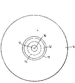
An optical fibre, comprising a glass core 10
surrounded by a glass cladding (II) of lower refractive
index, is provided with inner and outer relatively high
modulus plastics layers (12 and 14) spaced apart by a
relatively low modules layer 13. The low modules layer
is applied from an aqueous dispersion, and is dried but
not sintered. This leaves the layer (13) in a form in
which it has little adherence to the underlying inner
plastics layer (12), thereby enabling the outer layer
(14) to be readily peeled by mechanical means.


Claims

Note: Claims are shown in the official language in which they were submitted.

6
CLAIMS:
1. A plastics packaged glass optical fibre
having an outer layer of plastics packaging spaced
from an inner layer of plastics packaging by an
unsintered dispersion deposited intermediate layer of
plastics material.
2. A plastics packaged optical fibre as claimed
in claim 1, wherein the plastics material of said
intermediate layer is a fluoropolymer.
3. A plastics packaged optical fibre as claimed
in claim 2, wherein said fluoropolymer is pTFE.
4. A plastics packaged optical fibre as claimed
in claim 2, wherein said fluoropolymer is FFP.
5. A plastics packaged optical fibre as claimed
in claim 1, wherein the plastics material of said
outer layer is nylon.
6. A plastics packaged optical fibre as claimed
in claim 1, wherein said inner plastics layer is an
acrylate layer.
7. A plastics packaged optical fibre as claimed

7
in claim 6 wherein said inner acrylate plastics layer
is a composite layer having sub-layers of different
modulus.
8. A method of providing an optical fibre with
plastics packaging, in which method the fibre is
provided with a plastics coating upon which another
plastics coating is applied from an aqueous
dispersion, wherein the dispersion is dried without
producing a sintering of the residual material of the
coating, and wherein a further coating is applied over
the dried coating leaving the dried coating in its
unsintered state.
9. A method as claimed in claim 8, wherein the
aqueous dispersion is an aqueous fluoropolymer
dispersion.
10. A method as claimed in claim 9, wherein said
fluoropolymer is PTFE.
11. A method as claimed in claim 9, wherein said
fluoropolymer is FEP.
12. A plastics packaged optical fibre produced
by the method claimed in claim 8.

Description

Note: Descriptions are shown in the official language in which they were submitted.


_1_
PLASTICS PACKAGED OPTICAL FIBRE
This invention relates to plastics packaged
glass optical fibres. Glass optical fibres, typically '
those made of fused silica, are normally provided with a
plastics protective coating immediately after they are
drawn from preform. A primary function of such a
coating is to preserve, so far as is practically
possible, the initial strength of the freshly drawn .
fibre by protecting its surface from chemical attack and
from mechanical, damage resulting from it being allowed
to contact any solid surface other than that of the
coating itsalf. Typically the application of the
initial plastics projective coating is followed by the
application of one or more further coatings of plastics
material~to produce a complete plastics packaged optical
fibre. Not all of these further coatings are
necessarily applied on-line with the drawing of fibre
from preform. The thicknesses, moduli and expansion
coefficients of the individual layers comprising the
complete plastics packaging are normally chosen to
provide mechanical buffering from the fibre and
protection against micro-bending: A typical three-layer
structure comprises an acryl.ate inner layer, a nylon
outer layer and, between two layers, an intermediate
layer of lower modules material. Although described as
a three-layer package, the acrylate layer may be a
camposite layer built up from two or more componen t
sub-layers applied in succession, those sub-layers being

- 2 -
of slightly different acrylate composition, and hence of
slightly different modulus.
The present invention is concerned with
plastics packaged glass optical fibre having an outer
layer of plastics packaging spaced fram an inner layer
of plastics packaging by an intermediate layer of
plastics packaging, and provides a structure having the
property that the intermediate layer is not strongly
adherent to the inner layer, thus facilitating the
removal of the outer layer from the inner-by mechanical
stripping so as to leave the inner layer intact on the
underlying glass optical fibre. Mechanical
strippability of this sort is a desirable feature in
many applications in order to facilitate the preparation
of fibre splices and terminations.
According to the present invention there is~-
provided a plastics packaged glass optical fibre having
an outer layer of plastics packaging spaced from an
inner layer of plastics packaging by an unsintered
dispersion deposited intermediate Layer of plastics
material.
The invention also provides a a method of
providing an optical fibre with plastics packaging, in
which method the fibre is provided with a plastics
coating upon which another plastics coating is applied
from an aqueous dispersion, wherein the dispersion is
dried without producing a sintering of the residual
material of 'the coating, and wherein a further coating
is applied over the dried coating leaving the dried
coating in its unsintered state.
There follows a description of the manufacture
of a plastics packaged glass optical fibre embodying the
invention in a preferred form. 'rhe description refers
to the accompanying drawings in which:-
Figure 1 is a schematic representation of a
cross-section of the packaged fibre, arid
Figure 2 is a schematic representation of the
apparatus employed in the provision of the

- 3 --
intermediate and outer plastics packaging
layers of the fibre of Figure 1.
Referring to Figure l, a fused silica optical
fibre consists of an optical core region 10 surrounded
by a lower refractive index optical cladding region Il.
This fibre, which typically has a diameter of 125 dam, is
drawn from larger diameter optical fibre preform (not
shown). Immediately after being drawn from the tip of
the preform, and without first allowing it to come into
any contact with a solid surface, the freshly drawn
fibre is passed through one or more acrylate resin
filled coating baths (not shown), and the applied resin
is cured prior to collection of the fibre, for instance
on a drum (not shown) . The optical fibre, complete with
its acrylate coating 12, now typically has a diameter of
250 ~tm.
The optical fibre 10, I1, complete with its
acrylate inner coating 12, is subsequently provided with
an intermediate coating 13, and an outer coating 14,
using the apparatus of Figure 2. In Figure 2, the
fibre, complete with its acrylate coating, is depicted
at 20 where it is about to be introduced into an
applicator 21 via an entrance die 22, The applicator
contains an aqueous disgersion of
polytetrafluoroethylene (PTFE) at a pressure provided by
a head of the dispersion contained in a reservoir 23.
The fibre leaves the applicator 21 by way of an exit die
24, now coated with a thin layer of the aqueous
dispersion of PTFE.
In a particular example the aqueous dispersion
contained 55~ PTFE with an 0.3 ~m average particle size,
and included a wetting agent to reduce surface tension
and hence reduce any tendency for the coating to bead.
The viscosity of this dispersion was 1S mPa.s. The head
provided by the reservoir was about 10 cm. The two dies
22 and 24 had orifices 300 ~m in diameter. The line
speed was 40 metres per minute, and the thickness of the

_ g
resulting wet dispersion coating was about 20 ~m. At ,
high line speeds the dispersion is liable to experience
significant shear forces in the neighbourhood of the
exit die orifice, and hence it is desirable to use a
highly polished die made of a suitable material, such as
tungsten carbide, that will minimise the risk of
producing shear-induced coagulation of the dispersion.
The PTFE dispersion coated fibre proceeds a
short distance, typically about 0.5 metres, after
leaving the exit die before entering a drying oven 25.
Typically this drying oven is about 1.5 metres long.
Tnside the oven, a current of hot air provides a
temperature gradient designed to promote gradual
evaporation of the aqueous medium to leave a low modulus
particulate film 13 (Figure 1) of PFTE about 10 um thick
that will provide a cushion between the inner coating I2
and a yet-to-be-applied outer coating 14 (Figure 1).
The hot air flow is deliberately designed not to allow
the temperature of the coating to reach 380°C and thus
allow the PTFE to begin to sinter. This is because such
sintering would produce higher modulus material liable
to be much more strongly adherent to the underlying
coating 12. Furthermore, much more PTFE would be
required to produce a fully coherent sintered layer.
., After leaving the drying oven 25, the fibre now
complete with its inner and intermediate plastics
coatings 12 and 13 (Figure 1), proceeds a further short
distance, typically about 1.5 metres, before entering a
melt-extruder 26 containing nylon for the outer coating
14 of the plastics packaging. O.n emerging from the
melt-extruder, the fibre, now complete with its inner
intermediate and outer plastics packaging layers 12, 13
and 4, and typically having a diameter of about 0.8 mm,
enters a cooling trough 27 before being taken up on a
drum (not shown). The cooling provided by the Gaoling
trough 27 is regulated to produce the required amount of
crystallinity in the nylon and hence the appropriate

~~~~Q6~
- 5 -
thermal expansion properties to give the package fibre
its required strength without inducing excessive
micro-bending losses over the required service
temperature range.
The resulting optical fibre package is a tight
jacketed fibre whose outer layer is readily strippable
by mechanical means.
In a preferred construction the inner acrylate
coating 12 has a composite structure with an outer
sub-layer surrounding an inner sub-layer of lower
modules than the outer sub-layer, the boundary between -
these two layers being indicated in Figure 1 by the
broken line 15.
It is to be clearly understood that the invention is not
limited in its application solely to the specific
plastics materials exemplified in the foregoing specific
example: Thus an aqueous dispersion of FEP (fluorinated .
ethylene propylene) can be used in place of the aqueous
dispersion of PTEE as the material from which to make
the intermediate coating, and similarly an alternative
high performance thermoplastics material, such as a
polyester polyether or a liquid crystal polymer, can be
used in place of the nylon of the outer coating.

Representative Drawing
A single figure which represents the drawing illustrating the invention.
Administrative Status

2024-08-01:As part of the Next Generation Patents (NGP) transition, the Canadian Patents Database (CPD) now contains a more detailed Event History, which replicates the Event Log of our new back-office solution.

Please note that "Inactive:" events refers to events no longer in use in our new back-office solution.

For a clearer understanding of the status of the application/patent presented on this page, the site Disclaimer , as well as the definitions for Patent , Event History , Maintenance Fee  and Payment History  should be consulted.

Event History

Description Date
Inactive: IPC expired 2018-01-01
Inactive: Expired (new Act pat) 2012-06-11
Letter Sent 2009-09-23
Inactive: Multiple transfers 2009-08-13
Inactive: IPC from MCD 2006-03-11
Grant by Issuance 2001-10-30
Inactive: Cover page published 2001-10-29
Letter Sent 2001-08-16
Inactive: Final fee received 2001-06-29
Pre-grant 2001-06-29
Inactive: Single transfer 2001-06-22
Notice of Allowance is Issued 2001-01-10
Letter Sent 2001-01-10
Notice of Allowance is Issued 2001-01-10
Inactive: Approved for allowance (AFA) 2000-12-07
Inactive: Status info is complete as of Log entry date 1998-05-11
Inactive: Application prosecuted on TS as of Log entry date 1998-05-11
Request for Examination Requirements Determined Compliant 1996-07-08
All Requirements for Examination Determined Compliant 1996-07-08
Application Published (Open to Public Inspection) 1992-12-13

Abandonment History

There is no abandonment history.

Maintenance Fee

The last payment was received on 2001-06-06

Note : If the full payment has not been received on or before the date indicated, a further fee may be required which may be one of the following

  • the reinstatement fee;
  • the late payment fee; or
  • additional fee to reverse deemed expiry.

Patent fees are adjusted on the 1st of January every year. The amounts above are the current amounts if received by December 31 of the current year.
Please refer to the CIPO Patent Fees web page to see all current fee amounts.

Owners on Record

Note: Records showing the ownership history in alphabetical order.

Current Owners on Record
NORTHERN TELECOM LIMITED
PRYSMIAN CABLES & SYSTEMS LIMITED
Past Owners on Record
LAURA ELIZABETH PEARS
NIGEL SHACKLETON
Past Owners that do not appear in the "Owners on Record" listing will appear in other documentation within the application.
Documents

To view selected files, please enter reCAPTCHA code :


To view images, click a link in the Document Description column. To download the documents, select one or more checkboxes in the first column and then click the "Download Selected in PDF format (Zip Archive)" or the "Download Selected as Single PDF" button.

List of published and non-published patent-specific documents on the CPD .

If you have any difficulty accessing content, you can call the Client Service Centre at 1-866-997-1936 or send them an e-mail at CIPO Client Service Centre.


Document
Description 
Date
(yyyy-mm-dd) 
Number of pages   Size of Image (KB) 
Abstract 1994-03-29 1 20
Description 1994-03-29 5 205
Drawings 1994-03-29 1 14
Claims 1994-03-29 2 48
Representative drawing 1999-07-21 1 5
Commissioner's Notice - Application Found Allowable 2001-01-09 1 165
Courtesy - Certificate of registration (related document(s)) 2001-08-15 1 136
Courtesy - Certificate of registration (related document(s)) 2009-09-22 1 102
Correspondence 2001-06-28 1 33
Fees 1996-05-21 1 96
Fees 1995-05-23 1 98
Fees 1994-05-29 1 69